Latch Assembly Ford F150 Door Lock Diagram: Full Guide
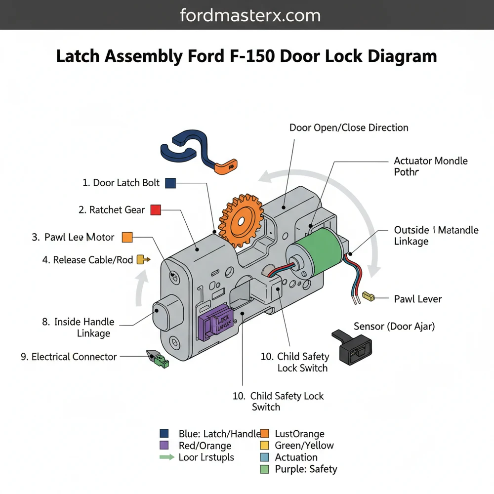
The latch assembly Ford F150 door lock diagram displays the mechanical and electrical interface between the door handle, lock actuator, and strike plate. This visual layout helps identify the internal structure, including cables, rod connections, and mounting points, ensuring you can correctly align and secure the locking configuration during repairs.
📌 Key Takeaways
- Provides a visual map of the door’s internal locking structure
- Crucial for identifying the power lock actuator and rod linkages
- Always disconnect the battery before handling electrical lock components
- Use the diagram to ensure rods are not bent during installation
- Ideal for troubleshooting doors that won’t latch or unlock
If you have ever found yourself struggling with a door that refuses to latch or a power lock that has suddenly gone silent, you understand the frustration of a malfunctioning vehicle entry system. Navigating the internal cavity of a truck door can be intimidating without a clear roadmap. Utilizing a comprehensive latch assembly ford f150 door lock diagram is the most effective way to demystify the complex mechanical and electronic interactions hidden behind your door panel. This guide provides a detailed overview of the system configuration, helping you identify every critical component and understand the structural layout required for successful repairs or maintenance. By the end of this article, you will have the technical knowledge to interpret a professional schematic and execute a precise replacement of your latch assembly.
Understanding the Latch Assembly System Layout
The door lock system in a modern truck is a hybrid of mechanical leverage and electronic actuation. When viewing a latch assembly ford f150 door lock diagram, the first thing you will notice is the central hub, which is the latch itself. This component is responsible for physically grabbing the striker bolt mounted on the vehicle’s B-pillar or C-pillar. The structure of this assembly is encased in a high-impact plastic and metal housing designed to withstand thousands of cycles.
In a standard schematic, you will see several distinct points of connection. First, there is the exterior handle rod or cable, which provides the mechanical pull needed to release the latch from the outside. Opposite this is the interior handle cable, which often features a more flexible design to navigate the inner door bracing. The blueprint also highlights the lock cylinder rod, which connects the physical keyhole to the latch mechanism, allowing for manual overrides.
Most modern Ford F150 models integrate the power lock actuator directly into the latch assembly. Older configurations used a separate motor connected by a rod, but newer systems utilize a “unitized” design where the electronics and mechanics are housed in a single non-serviceable component.
The electronic configuration is represented in the diagram by a multi-pin connector, usually located at the bottom or rear of the assembly. This plug receives signals from the Body Control Module (BCM) to trigger the locking motor and sends signals back to the truck to confirm if the door is “ajar” or closed. Understanding this layout is vital because a failure in the door-ajar switch—a tiny component inside the latch—is a frequent cause of battery drain and interior light issues.
How to Read and Apply the Latch Assembly Schematic

Interpreting a technical blueprint of your door’s internal structure requires a methodical approach. To use the latch assembly ford f150 door lock diagram effectively for a repair, follow these steps to ensure you are identifying the right parts and following the correct path of disassembly.
- ✓ Step 1: Identify the Mounting Points – Look at the diagram for three primary Torx-head bolts on the edge of the door. These are the structural anchors for the entire assembly.
- ✓ Step 2: Trace the Cable Routes – Follow the lines in the schematic from the interior handle to the latch. Note how the cable clips into the door’s metal inner skin.
- ✓ Step 3: Locate the Electrical Harness – Find the plug symbol on the diagram. In the physical door, this is often tucked behind a window track, making it difficult to see without a mirror.
- ✓ Step 4: Check for Window Track Interference – The schematic will show a vertical bar representing the rear window guide. You will usually need to loosen this guide to wiggle the latch assembly out.
- ✓ Step 5: Disconnect Manual Rods – Using the diagram, identify the plastic “flip-clips” that hold the metal rods in place. These must be rotated off the rod before the rod can be pulled out of the latch socket.
- ✓ Step 6: Remove and Replace – Once all connections identified in the blueprint are cleared, the assembly slides down and out through the large access hole in the door frame.
Always disconnect the negative battery terminal before working on the latch assembly. Since the system is tied to the central locking and alarm, accidental shorts can trigger the horn or potentially damage the Body Control Module.
To perform this work, you will need a specific set of tools: a set of Torx bits (specifically T27 and T30), a flat-head screwdriver or trim removal tool for the door panel, and a 10mm socket for the window track bolts. Having the latch assembly ford f150 door lock diagram taped to your workstation allows you to cross-reference your progress and ensures no small clips or washers are left behind during reassembly.
Troubleshooting Common Lock and Latch Issues

Even with a high-quality blueprint, diagnosing the specific failure point requires observational skills. The latch assembly ford f150 door lock diagram helps you isolate whether a problem is mechanical or electrical. If you hear a “whirring” sound when pressing the lock button but nothing happens, the schematic points you toward the internal gears of the actuator. This indicates the motor is receiving power, but the plastic teeth inside have stripped.
If the door refuses to open from the outside but works fine from the inside, the diagram directs your attention to the exterior handle rod. These rods can sometimes pop out of their plastic retainers or the retainers themselves can snap. Conversely, if the door “bounces” back when you try to shut it, the mechanical claw within the latch is likely stuck in the closed position or the return spring has snapped.
Before replacing the entire assembly, check the wiring harness in the rubber “accordion” boot between the door and the truck frame. Constant opening and closing can fatigue the wires, causing intermittent lock failure that mimics a bad latch.
Another common issue involves the “door ajar” warning staying on. By looking at the electrical configuration of the latch assembly, you can see that the switch is integrated. Often, dirt and old grease gum up this switch. Using the diagram to locate the latch opening, you can sometimes spray a specialized electronic cleaner into the mechanism to free the switch without removing the entire door panel.
Maintenance and Quality Component Selection
Longevity of your door lock system depends heavily on proper maintenance and the quality of replacement parts. When your latch assembly ford f150 door lock diagram indicates the need for a full unit swap, you must choose between OEM (Original Equipment Manufacturer) and aftermarket options. OEM parts are generally recommended for the F150 because the tolerances for the cable tension are very specific; minor deviations in aftermarket cable lengths can lead to a handle that feels “mushy” or fails to engage.
For maintenance, avoid using heavy greases or WD-40 inside the latch. Over time, these attract road dust and debris, creating a thick paste that slows down the actuator. Instead, use a dry PTFE lubricant or a high-quality graphite spray. Referencing your system overview, apply the lubricant to the pivot points of the rods and the main latching jaw.
When installing a new assembly, ensure the vapor barrier (the plastic sheet behind the door panel) is resealed perfectly. A leak here allows moisture to reach the latch electronics, significantly shortening the lifespan of the new component.
Lastly, keep an eye on the door alignment. If the door is sagging, it puts undue stress on the latch assembly as it tries to climb onto the striker. This mechanical strain eventually burns out the lock motor. Use your diagram to understand how the latch meets the striker and adjust the door hinges if the alignment looks off-center.
In conclusion, mastering the latch assembly ford f150 door lock diagram is the key to maintaining your truck’s security and functionality. By understanding the component layout, following a systematic removal process, and troubleshooting based on the structural design, you can save significant time and money on repairs. Whether you are dealing with a frozen lock in winter or a snapped cable in the heat of summer, having a clear schematic ensures that your Ford F150 remains easy to access and secure. Always prioritize high-quality components and clean lubrication to keep your door lock system operating smoothly for years to come.
Step-by-Step Guide to Understanding the Latch Assembly Ford F150 Door Lock Diagram: Full Guide
Identify the main latch body and its mounting points on the door frame using the diagram.
Locate the electrical connector for the power lock actuator and the mechanical rod clips.
Understand how the cable configuration links the interior and exterior handles to the central latch.
Connect the replacement assembly to the existing wiring harness and manual linkages correctly.
Verify that the latch clicks into the strike plate and releases smoothly when the handle is pulled.
Complete the installation by securing the mounting bolts and reinstalling the interior door panel.
Frequently Asked Questions
Where is the latch assembly located?
It is mounted inside the door shell on the trailing edge. To access it, you must remove the interior door panel and peel back the moisture barrier. The assembly sits between the exterior handle and the door frame, secured by three Torx bolts on the side of the door.
What does the latch assembly Ford F150 door lock diagram show?
The diagram details the full system structure, highlighting the relationship between the mechanical latch, the electrical lock actuator, and the connecting rods or cables. It provides a visual layout of how the interior and exterior handles trigger the release mechanism to open or secure the door.
How many connections does the latch assembly have?
Most modern Ford F150 assemblies feature one primary electrical connector for the power lock actuator and several mechanical linkages. These include cable or rod connections for the interior handle, exterior handle, and manual lock cylinder, creating a complex configuration that coordinates electronic and manual operation.
What are the symptoms of a bad door lock latch?
Common signs include doors that bounce back when closing, locks that won’t engage via remote, or handles that feel loose. If you hear a grinding noise or the door remains stuck shut, the internal component gears or the integrated actuator motor have likely failed within the system.
Can I replace the latch assembly myself?
Yes, this is a manageable DIY task for those with basic hand tools. You will need to remove the door panel and maneuver the assembly through the access hole. While the configuration is tight, following a diagram makes identifying cable positions and bolt locations significantly easier for owners.
What tools do I need for this task?
You typically need a set of Torx bits (T25, T27, or T30), a socket set for door panel bolts, and a plastic trim removal tool. A flashlight is also essential for seeing the internal layout and ensuring all component clips are properly seated during the reinstallation process.