Latch Assembly Ford Explorer Door Latch Diagram Guide
The latch assembly ford explorer door latch diagram illustrates the mechanical and electrical structure of the door locking system. It details how the actuator, cables, and locking mechanism integrate within the door frame configuration, allowing you to identify failed components or misaligned linkages for efficient troubleshooting and replacement.
📌 Key Takeaways
- Visualizes the internal door lock mechanism and mounting points
- Helps distinguish between the power lock actuator and mechanical cables
- Crucial for identifying electrical pin configurations for sensors
- Used for diagnosing door-ajar light errors and latch failures
- Essential reference when replacing jammed or faulty latch units
Understanding the internal mechanics of your vehicle is essential for successful DIY maintenance and repairs. If you are currently struggling with a door that fails to open, lock, or stay closed, a detailed latch assembly Ford explorer door latch diagram is your most valuable asset. This schematic provides a visual blueprint of the intricate locking system, allowing you to identify specific components before you begin disassembly. In this guide, we will break down the layout of the latch system, explain how to interpret the technical configuration, and provide a step-by-step approach to diagnosing and fixing common door issues.
Understanding the Latch Assembly Structure and Layout
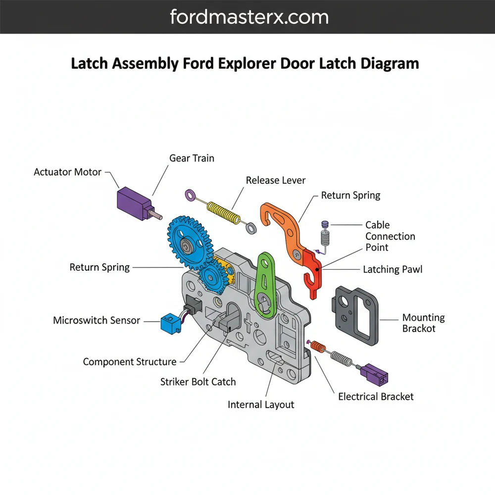
The door latch system in a Ford Explorer is a complex mechanical and electrical hybrid. To use a latch assembly Ford explorer door latch diagram effectively, you must first understand the primary components that constitute the assembly’s structure. The latch is not a single piece of metal but a sophisticated housing that manages three distinct functions: physical latching, power locking, and door status sensing.
In a typical schematic overview, you will see the central latch unit positioned at the trailing edge of the door. This component is the “brain” of the door’s physical security. Inside this housing is the door lock actuator, which is a small motor responsible for moving the locking pawl. On many models, this actuator is integrated directly into the assembly, while older versions may show it as a separate unit connected by a short rod.
The layout of the system is defined by its connection points. The diagram will highlight several critical pathways:
- ✓ Interior Release Cable: Connects the inside handle to the latch lever.
- ✓ Exterior Handle Rod: A vertical metal rod that triggers the release when the outside handle is pulled.
- ✓ Lock Cylinder Rod: Connects the physical key slot to the locking mechanism.
- ✓ Electrical Harness: A multi-pin connector that provides power to the motor and sends the “door ajar” signal to the vehicle’s computer.
Variations in this configuration often depend on whether the vehicle is equipped with keyless entry or child safety locks. The blueprint for the rear doors will feature an additional manual toggle switch used to disable the interior handle. Understanding these nuances in the diagram helps you avoid damaging sensitive plastic clips during the removal process.
[DIAGRAM_PLACEHOLDER: A detailed exploded-view schematic of a Ford Explorer door latch assembly, showing the central housing, the integrated actuator, the three connecting rods (interior, exterior, and lock cylinder), and the 6-pin electrical connector.]
How to Read and Apply the Latch Assembly Schematic

Reading a technical blueprint of a door system requires a systematic approach. You are looking at a three-dimensional object represented in two dimensions, so spatial awareness is key. Follow these steps to translate the latch assembly Ford explorer door latch diagram into a successful repair.
Before beginning, verify if your specific model uses a cable-driven or rod-driven interior release. This significantly changes how you disconnect the interior trim panel from the door shell.
- Identify the Fastener Locations: Look at the diagram to locate the three primary Torx bolts (usually T27 or T30) on the outer edge of the door. These are the main structural supports for the entire assembly.
- Locate the Access Points: The schematic will show the internal cavity of the door. Use this to find the plastic “Christmas tree” clips and screws hidden behind the door handle cover and the armrest. Removing the door panel is the first physical step to reaching the latch.
- Manage the Vapor Barrier: Behind the panel is a plastic sheet. The diagram layout implies that the latch is located in the upper rear quadrant. Peel back only as much of the adhesive barrier as necessary to reach the assembly.
- Disconnect the External Rods: Using the diagram as a guide, locate the colored plastic clips (often yellow, green, or pink) that hold the metal rods in place. You must flip the clip off the rod before the rod can be pulled out of the socket.
- Unplug the Electrical Connector: The wiring harness usually has a squeeze-tab. The diagram will show the orientation of this plug. Be careful not to pull on the wires themselves, as this can damage the pins inside the latch housing.
- Remove the Latch Assembly: Once the rods and wires are free, unscrew the exterior Torx bolts. The entire unit will drop slightly inside the door. You will need to maneuver it around the window track (glass should be in the “up” position) to extract it through the large access hole in the door frame.
- Verify the Replacement Unit: Compare your new part to the configuration shown in the blueprint. Ensure all levers and spring-loaded arms move freely before installation.
- Reassembly and Testing: Reverse the process. Always test the latch manually with a screwdriver while the door is open to ensure it “catches” and “releases” before you actually close the door.
Never close the door after installing a new latch until you have tested the release mechanism with the door panel off. If the rods are not adjusted correctly, you may end up with a “deadlocked” door that is extremely difficult to open.
Common Issues and Troubleshooting with the Latch System

Even with a high-quality latch assembly Ford explorer door latch diagram, you may encounter specific diagnostic challenges. Ford Explorer models often face a few recurring issues related to this system.
One of the most frequent problems is the “Door Ajar” light remaining on even when the door is securely closed. The diagram shows a small micro-switch located inside the latch housing. Over time, dust and dried factory grease can prevent this switch from clicking into the “closed” position. Often, a liberal application of electrical contact cleaner or WD-40 into the latch mechanism can resolve this without replacing the whole unit.
Another common failure is a “spinning” or “loose” door handle feeling. By referring to the system schematic, you can determine if the failure is in the handle itself or if the rod has simply popped out of its plastic clip. If the actuator makes a buzzing or grinding noise but doesn’t move the lock, the internal plastic gears have likely stripped, necessitating a full assembly replacement.
Pro Tips and Maintenance for Longevity
To ensure your latch system remains functional for years, follow these best practices derived from professional automotive technicians.
When installing a new latch, use a small amount of white lithium grease on the moving external parts. Avoid using heavy wheel bearing grease, as it attracts road grit which can lead to premature wear.
When sourcing parts, it is often tempting to buy the cheapest aftermarket option. However, because the latch assembly is a critical safety component (it keeps the door closed during an impact), many experts recommend using OEM (Original Equipment Manufacturer) parts. OEM units typically match the latch assembly Ford explorer door latch diagram perfectly, ensuring that rod lengths and electrical pinouts are identical to the factory configuration.
Maintenance is simple but often overlooked. Once a year, clean the visible part of the latch on the door edge with a rag and apply a light spray of dry silicone lubricant. This keeps the mechanism smooth and prevents the rubber seals from sticking to the striker plate in freezing temperatures.
By combining a clear understanding of the component layout with a methodical approach to the repair, you can successfully navigate any issues with your vehicle’s entry system. Whether you are performing a full replacement or just a simple cleaning, the latch assembly Ford explorer door latch diagram is the essential roadmap for the job.
Step-by-Step Guide to Understanding the Latch Assembly Ford Explorer Door Latch Diagram Guide
Identify the mounting bolts on the door edge and the electrical connector locations using the diagram.
Locate the interior door panel clips and remove the panel to expose the internal component structure.
Understand how the handle rods and cables attach to the latch assembly mechanism within the system.
Apply the diagram’s layout to disconnect the power lock actuator harness and mechanical linkages safely.
Verify that the new latch assembly aligns with the factory mounting holes and door frame configuration.
Complete the installation by reattaching the panel and testing the locking function for smooth operation.
Frequently Asked Questions
Where is the latch assembly located?
The assembly is mounted inside the door shell, secured to the rear edge of the door frame by three Torx bolts. You must remove the interior door panel to access its internal structure and disconnect the handle cables and electrical harness from the locking system layout.
What does this latch diagram show?
This diagram provides a detailed view of the latch assembly ford explorer door latch diagram, highlighting the relationship between the lock actuator, interior release cables, and mounting points. It helps visualize how each component interacts within the larger vehicle security system configuration for easier repair.
How many electrical pins does the latch have?
Most modern Ford Explorer door latch assemblies feature a 6-pin or 8-pin electrical connector. This configuration handles the power lock signals, the door-ajar sensor switch, and the keyless entry inputs, ensuring the central locking system communicates correctly with the vehicle’s body control module.
What are the symptoms of a bad door latch?
Common symptoms include the door failing to stay shut, power locks not responding, or a persistent door-ajar warning on the dashboard. A faulty internal switch or broken mechanical component within the assembly structure often causes these issues, requiring a full inspection of the internal door layout.
Can I replace this assembly myself?
Yes, replacing the latch is a manageable DIY task for those with basic tools. You will need to remove the door panel, disconnect the window tracks in some cases, and unhook the mechanical cables. Following the latch assembly ford explorer door latch diagram ensures correct reinstallation.
What tools do I need for this task?
You will typically need a set of Torx bits (T20 to T30), a trim removal tool for the door panel, a socket wrench set, and a screwdriver. These tools allow you to navigate the internal door layout and safely remove the mounting hardware from the system.