Ford Radio Wiring Harness Color Codes: The Definitive Engineering Guide (1980–2026)
The evolution of automotive audio wiring is not merely a history of changing plugs and wire colors; it is a chronicle of the automotive industry’s transition from purely mechanical and analog electrical systems to highly integrated, software-driven networks. For the automotive technician, the audiophile, or the dedicated DIY enthusiast working on a Ford vehicle, understanding this evolution is paramount. A wire is no longer just a wire; in modern applications, it is a data carrier, a logic signal, or a part of a complex differential pair.
Ford Motor Company, perhaps more than any other manufacturer, exemplifies this radical shift. Over the last four decades, Ford’s approach to factory radio wiring has moved from simple, common-ground analog circuits in the “Bullnose” trucks of the 1980s to the standardized “World Plug” of the late 1990s, and finally to the Controller Area Network (CAN-bus) integrated systems of the 21st century.
This report serves as a comprehensive technical repository, synthesizing data from electrical vacuum troubleshooting manuals (EVTM), factory service bulletins, and connector pinout databases to provide the definitive reference for Ford radio wiring.
The primary challenge in modifying, repairing, or upgrading a Ford audio system lies in navigating the disparities between the standardized aftermarket (EIA) protocols and Ford’s proprietary OEM engineering decisions. A 2003 Ford F-150 and a 2005 Ford F-150 share a nameplate, yet their electrical DNA is entirely distinct due to the industry-wide shift from the “World Plug” to the “Phase 2” connector system.
Furthermore, modern vehicles equipped with SYNC 2 and SYNC 3 systems have abandoned the traditional 12V switched ignition wire entirely, relying instead on hexadecimal data packets sent over the Medium-Speed CAN (MS-CAN) network to wake the Audio Control Module (ACM).
This document provides a granular analysis of these systems, breaking down wire colors, pin positions, and signal types for high-volume models including the F-150, Mustang, Explorer, and Focus. It bridges the gap between abstract electrical theory and practical, hands-on application.
FORD AUDIO ANATOMY
The ultimate visual guide to deciphering Factory vs. Aftermarket radio wiring standards.
The “Rosetta Stone” of Car Audio
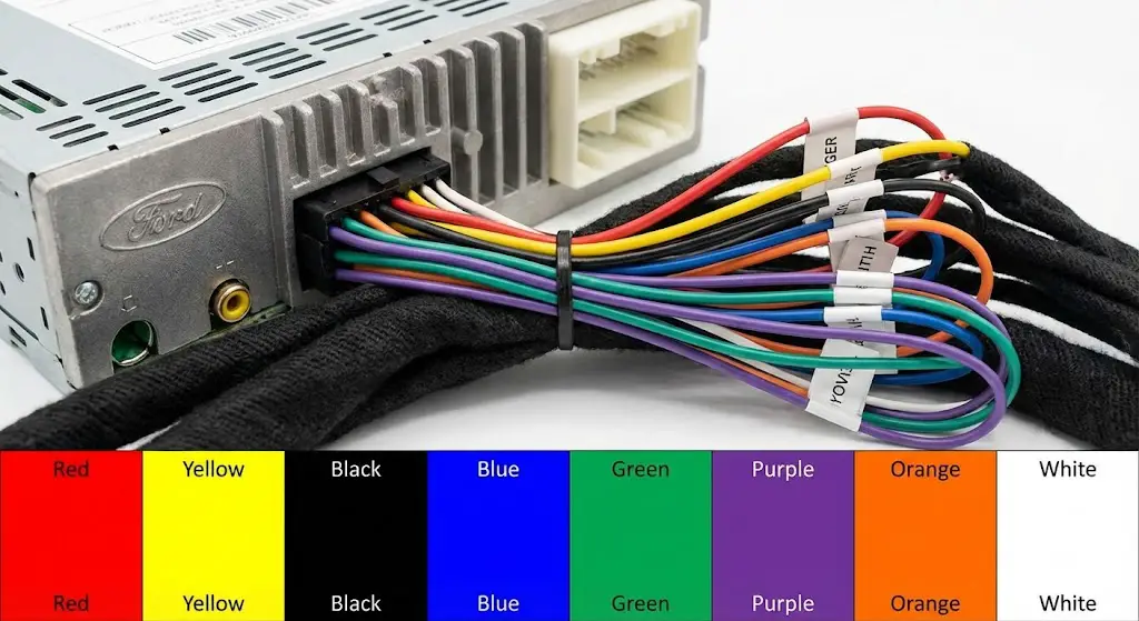
Connecting a modern head unit to a Ford factory harness is simpler than it looks, provided you understand the translation. Standard aftermarket radios use the **EIA (Electronic Industries Alliance)** color code system. However, factory Ford plugs (especially the “World Plugs” of the 90s and 00s) use a different palette entirely.
This infographic bridges the gap, visualizing the pinouts, voltages, and color codes you need to know.
1 Harness Wire Composition
A standard radio harness isn’t just power. It’s mostly audio signal carriers. Understanding the proportion of wires helps you identify bundles quickly. If you see a twisted pair, it’s likely a speaker line.
- Speaker Outputs (50%) 8 Wires
- Power & Ignition (12.5%) 2 Wires
- Ground (6.25%) 1 Wire
- Triggers (Remote/Ant) (12.5%) 2 Wires
- Illumination/Dimmer (12.5%) 2 Wires
2 Critical Voltage Checks
Before crimping a single butt connector, verify your factory lines with a Digital Multimeter. Misidentifying the “Constant 12V” vs. “Switched 12V” is the #1 cause of battery drain in aftermarket installs.
3 Ford “World Plug” Pinout
Used widely from the late 80s to mid-2000s, this 2-plug system is the most common Ford configuration.
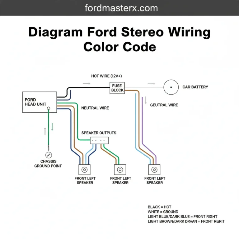
The Power Plug (Grey Connector)
- Yellow/Green: Constant 12V+
- Red/Black: Switched 12V+ (Ignition)
- Black/Green: Ground
- Blue/Red: Amp/Antenna Trigger
The Speaker Plug (Black Connector)
- White/Green Pair: Right Front
- Orange/Green Pair: Left Front
- Pink/Blue Pair: Right Rear
- Pink/Green Pair: Left Rear
4 Troubleshooting Logic
Radio won’t turn on? No sound? Follow this logical path to isolate the wire at fault.
Step 1: Does the unit power on?
If NO: Check the Yellow (Constant) and Red (Ignition) wires. Both must show 12V+ (Yellow always, Red only when key is turned).
Step 2: Power is OK, but No Sound?
Check for a Factory Amplifier. Many Fords have a hidden amp. You may need to connect the Blue/White (Remote Turn On) wire to the factory harness.
Step 3: Sound is distorted/weak?
Check Speaker Phase. If (+) and (-) are reversed on one speaker, it will cancel out bass frequencies. Verify polarity.
Step 4: Radio forgets settings?
Yellow and Red wires are likely swapped. The Yellow wire MUST have constant battery power to save station memory.
5 The Evolution of Ford Audio
The “Common Ground” Era
Speakers often shared a single ground wire attached to the chassis. Modern radios require “Floating Grounds” (separate +/- for each speaker). Adapters are mandatory here.
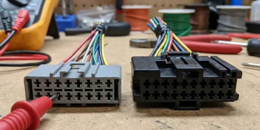
The “World Plug” Era
Standardized Grey (Power) and Black (Speaker) rectangular plugs. Easy to work with, identifiable colors. The golden age of DIY installs.
The CAN-BUS Era (Quadlock)
Big square plugs. The “Switched 12V” wire disappears from the harness, replaced by data signals. You now need a specialized interface box to interpret ignition signals.
© 2025-2026 FordMasterX Infographics. Data sourced from manufacturer owner manuals.
The Fundamental Divergence: Aftermarket vs. Factory Standards
To successfully navigate Ford wiring, one must first master the distinction between the two prevailing color code standards: the Electronic Industries Association (EIA) standard used by the aftermarket industry, and the Ford OEM standard used on the assembly line. These two systems are fundamentally incompatible in terms of color logic, and confusing them is the primary cause of blown fuses, fried head units, and parasitic battery drains.
The EIA Aftermarket Standard (The "New" Harness)
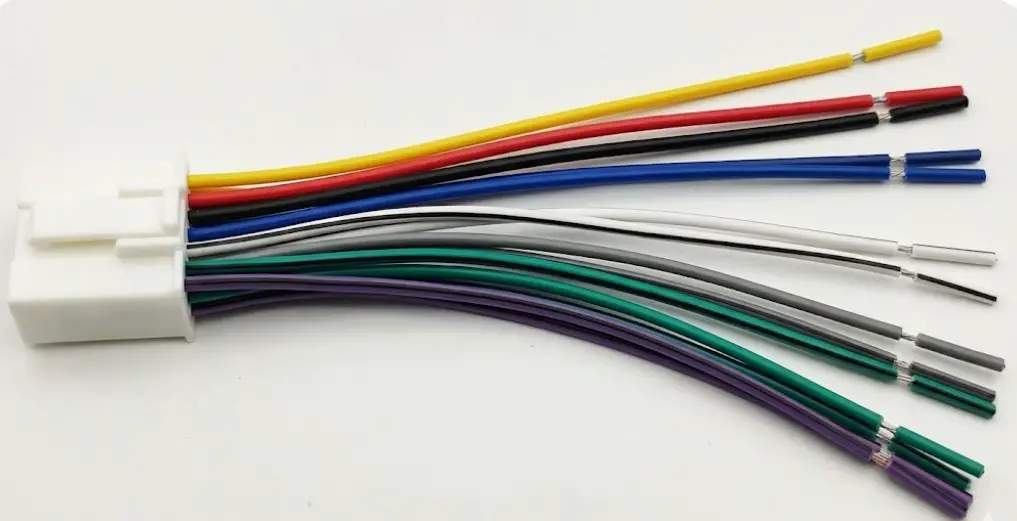
Almost every aftermarket head unit manufacturer—Pioneer, Kenwood, Alpine, Sony—adopts the EIA color code standard for their wiring harnesses. When a technician purchases a vehicle-specific adapter (such as a Metra, Scosche, or PAC harness), the wires extending from that adapter follow this EIA standard to facilitate easy matching with the new radio.
Understanding the EIA standard is the baseline for any installation. It provides a universal language that allows a radio manufactured in 2024 to be installed in a vehicle from 1994.
Table 1: EIA Standard Color Code Reference
| Wire Color | Function | Polarity | Signal Type |
| Yellow | Constant 12V (Memory/Battery) | Positive (+) | High Current / Logic Power |
| Red | Accessory/Ignition 12V | Positive (+) | Switched Signal |
| Black | Chassis Ground | Negative (-) | Ground Reference |
| Blue | Power Antenna | Positive (+) | Trigger Output (+12V) |
| Blue/White | Amplifier Remote Turn-On | Positive (+) | Trigger Output (+12V) |
| Orange | Illumination (Variable) | Positive (+) | Variable Voltage |
| Orange/White | Dimmer (On/Off or PWM) | Positive (+) | Signal |
| White | Left Front Speaker | Positive (+) | Analog Audio (AC) |
| White/Black | Left Front Speaker | Negative (-) | Analog Audio (AC) |
| Gray | Right Front Speaker | Positive (+) | Analog Audio (AC) |
| Gray/Black | Right Front Speaker | Negative (-) | Analog Audio (AC) |
| Green | Left Rear Speaker | Positive (+) | Analog Audio (AC) |
| Green/Black | Left Rear Speaker | Negative (-) | Analog Audio (AC) |
| Purple | Right Rear Speaker | Positive (+) | Analog Audio (AC) |
| Purple/Black | Right Rear Speaker | Negative (-) | Analog Audio (AC) |
The Ford OEM Standard (The "Factory" Harness)
Unlike the rigid EIA standard, Ford's factory wiring colors are fluid. They change not only between models but often between trim levels and production years within the same generation. A ground wire might be solid black in a 1998 F-150, but black with a green stripe in a 2004 model. Ignition power might be Black/Pink in one era and replaced by a data signal in the next.
This variability necessitates a "verify then connect" approach. Technicians cannot rely solely on color charts found on casual forums; they must correlate wire position (pinout) with function. The physical position of a pin in a connector shell is generally more consistent than the color of the wire insulation crimped to it.
The Analog Age – Phase 1 & Common Ground (1980–1997)
The period spanning the 1980s through the mid-1990s represents the analog zenith of automotive audio. During this era, wiring was direct: a switch physically closed a circuit to send 12 volts to the radio. There were no computers negotiating the power state. However, this simplicity came with its own set of archaic engineering standards, most notably the "Common Ground" system and the split-connector designs.
The "Bullnose" and OBS F-Series Architecture (1980–1996)
For the Ford F-Series—spanning the "Bullnose" (1980–1986), "Bricknose" (1987–1991), and "OBS" (Old Body Style, 1992–1996)—the wiring interface typically consisted of two separate connectors: a power plug (often grey) and a speaker plug (often black).
The Power Connector (C333 / Grey)
The power connector in these trucks is a source of confusion because the color logic contradicts modern conventions.
- Yellow with Black Hash Marks: This is the Switched 12V (Ignition) wire. In modern cars, yellow is constant; in 1980s Fords, yellow (with hash) is switched. Confusing these leads to a radio that never turns off or loses memory constantly.
- Light Green with Yellow Stripe: This is the Constant 12V (Memory) wire.
- Light Blue with Red Stripe: This is the Dashboard Illumination wire. It carries variable voltage from the headlight rheostat to dim the display.
- Red or Black: Chassis Ground. In many early 80s models, there was no ground wire in the harness; the radio grounded physically through its metal chassis mounting bracket. Installing a modern radio in these trucks often requires running a new, dedicated ground wire to the vehicle frame.
The Speaker Connector (C522 / Black)
The speaker wiring in this era highlights the "Common Ground" architecture used in lower-trim vehicles.
- Orange/Light Green: Left Front (+)
- Pink/Light Green: Left Rear (+)
- White/Light Green: Right Front (+)
- Pink/Light Blue: Right Rear (+)
- Black/White: Common Ground (-)
The Common Ground Danger: In many base-model Fords from the early 80s, the negative wires for all speakers were spliced together into a single "common" return path to the radio. Modern high-power aftermarket head units use "floating ground" or bridged amplifier designs. Connecting a modern floating-ground radio to a vintage common-ground speaker system will cause the internal amplifier chip to overheat and fail, or trigger protection mode. The solution is strictly re-wiring: the technician must run new positive and negative wires to each speaker individually, bypassing the factory common ground harness entirely.
The Premium Sound Era (Bronco & Lariat)
Higher trim levels, such as the Bronco XLT or F-150 Lariat, often featured the "Premium Sound" package. This introduced an external amplifier, usually located under the dashboard or seats.
- Wiring Implication: The wires behind the radio in these vehicles are not speaker wires; they are low-level signal wires feeding the amp. connecting a high-powered aftermarket radio's speaker outputs directly to these wires results in severe distortion (double amplification).
- Bypass Strategy: Technicians typically use an "Amp Bypass Harness" (like the Metra 70-5514) which jumper the input and output plugs of the factory amplifier, effectively removing it from the circuit and allowing the aftermarket radio to drive the speakers directly.
The Standardization – The "World Plug" (1998–2004/5)
As vehicle electronics became more sophisticated in the late 1990s, Ford sought to standardize their audio interfaces globally. This effort culminated in the introduction of the 16-pin connector, colloquially known as the "World Plug" (Metra Part 70-1771). This connector became the standard for millions of vehicles, including the Ford Ranger, Explorer, Taurus, and the "New Edge" Mustang.
The World Plug (16-Pin) Pinout Anatomy
This connector (often designated C290 in service manuals) consolidated power, ground, and speaker connections into a single block. It represents the most "user-friendly" era of Ford wiring, as it largely standardized colors and functions across the fleet.
Table 2: Ford "World Plug" 16-Pin Connector Pinout (1998-2004)
| Pin # | Wire Color (Factory) | Function | Matching EIA Color |
| 1 | White / Light Green | Right Front Speaker (+) | Gray |
| 2 | Dark Green / Orange | Right Front Speaker (-) | Gray/Black |
| 3 | Orange / Light Green | Left Front Speaker (+) | White |
| 4 | Light Blue / White | Left Front Speaker (-) | White/Black |
| 5 | Gray / Light Blue | Left Rear Speaker (+) | Green |
| 6 | Tan / Yellow | Left Rear Speaker (-) | Green/Black |
| 7 | Orange / Red | Right Rear Speaker (+) | Purple |
| 8 | Brown / Pink | Right Rear Speaker (-) | Purple/Black |
| 9 | Black | Chassis Ground | Black |
| 10 | Blue / Red | Illumination / Dimmer | Orange |
| 11 | Black / Pink | Ignition / Switched 12V (+) | Red |
| 12 | Green / Violet | Constant 12V / Battery (+) | Yellow |
| 13 | Black / Green | Amp Ground (Premium Sound) | N/A |
| 14 | Blue | Power Antenna (if equipped) | Blue |
| 15 | Blue / White | Amp Turn-On (Premium Sound) | Blue/White |
| 16 | N/A | (Often Empty) | N/A |
Diagnostic Case Study: The "Phantom Memory" Loss: A common issue in 1998–2003 F-150s involves the radio losing presets despite correct wiring. This is often traced to Pin 12 (Green/Violet). Unlike the ignition wire, this constant power line is fused separately in the Power Distribution Box (under the hood) rather than the interior fuse panel. A blown fuse here cuts memory power while leaving the radio operational when the car is running (via the switched feed), leading to user confusion. Technicians should always verify Pin 12 voltage with the key off.
The Mach Audio Systems (Mustang SN95)
The "World Plug" era also hosted the complex Mach 460 and Mach 1000 audio systems found in the SN95 Mustangs (1994–2004). These systems utilized the standard World Plug for power and primary signals but added a secondary 8-pin connector for the subwoofer amplifiers.
- Architecture: The Mach 460 system uses three amplifiers: one for the front tweeters (powered by the head unit or a small amp) and two for the "woofers" in the doors and rear deck. The signal sent from the head unit is a specific voltage (typically 5V low-level).
- Integration Challenge: Connecting an aftermarket radio's high-voltage speaker outputs (up to 9V-12V) into the Mach factory amp inputs causes extreme distortion and potential amp failure.
- Solution: Correct integration requires a harness with RCA plugs (Metra 70-5519) that connects to the aftermarket radio's pre-amp outputs, ensuring the correct signal level reaches the factory amplifiers.
The Transitional Phase – "Phase 2" & CAN-Bus Introduction (2004–2014)
With the launch of the 11th Generation F-150 in 2004 and the S197 Mustang in 2005, Ford debuted the "Phase 2" wiring architecture. This era is characterized by a physically larger, 24-pin main connector (Metra 70-5520) and the creeping integration of the Controller Area Network (CAN-bus) into audio functions.
This period represents a "hybrid" state. Early Phase 2 vehicles still retained analog power wires (12V switched), but later models (2011+) began to phase them out in favor of data signals.
The Phase 2 (24-Pin) Connector Pinout
This connector, often bulky and grey or black, carries power, ground, speakers, and the emerging CAN-bus data lines.
Table 3: Ford "Phase 2" 24-Pin Connector Pinout (2004-2014)
| Pin # | Wire Color | Function | Polarity |
| 1 | White/Red (or Green/Purple) | Constant 12V (Battery) | (+) |
| 2 | Blue/White (or Pink/Black) | Ignition / Switched 12V | (+) See Note Below |
| 8 | Black/Blue | Ground | (-) |
| 9 | White | Left Front Speaker | (+) |
| 10 | White/Brown | Left Front Speaker | (-) |
| 11 | White/Purple | Right Front Speaker | (+) |
| 12 | White/Orange | Right Front Speaker | (-) |
| 13 | Black | Ground (Redundant) | (-) |
| 14 | Gray/Blue | Illumination/Dimmer | (+) |
| 18 | Gray/Blue | MS-CAN + (Data) | Data High |
| 19 | Tan/Orange | MS-CAN - (Data) | Data Low |
| 21 | White/Green | Left Rear Speaker | (+) |
| 22 | Brown/Yellow | Left Rear Speaker | (-) |
| 23 | Brown/White | Right Rear Speaker | (+) |
| 24 | Brown/Blue | Right Rear Speaker | (-) |
The "Disappearing" Ignition Wire (2008+):
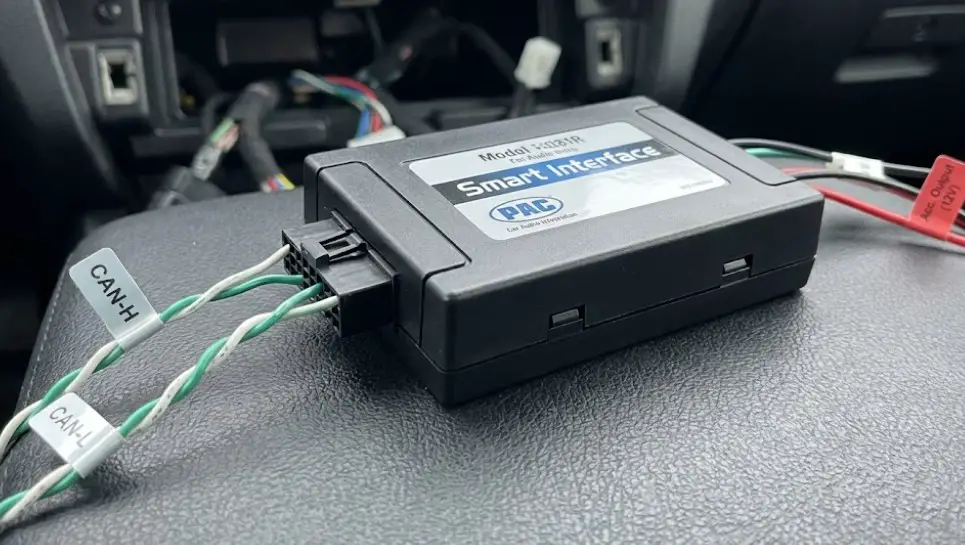
In many Ford vehicles manufactured after 2008 (such as the Focus, Edge, and later F-150s), Pin 2 (Ignition 12V) was deprecated. The factory radio no longer relied on a physical 12V surge to turn on. Instead, it listened for a digital "Wake Up" command sent over the CAN-bus lines (Pins 18 & 19).
- Implication for Installers: If you use a basic wiring harness on a 2010 F-150, the new aftermarket radio will not turn on because there is no 12V power on the ignition wire.
- The Fix: You must source a switched 12V signal from elsewhere (fuse box, cigarette lighter) or, preferably, use a "Smart Interface" harness (like PAC RP4-FD11) that reads the CAN signal and generates a synthetic 12V output for the radio.
The Shaker 500 & 1000 Systems (Mustang S197)
The S197 Mustang (2005-2014) featured the Shaker audio systems, which are notorious for the "Turn-On Pop" issue.
- The Problem: The factory amplifiers for the door subwoofers (Shaker 500) and trunk subwoofers (Shaker 1000) utilize a 5-volt logic signal for their remote turn-on. Standard aftermarket radios output a 12-volt remote signal.
- The Symptom: When 12V hits the 5V input, the amplifier engages aggressively, causing a loud, damaging "thump" or "pop" from the subwoofers every time the radio turns on.
- The Engineering Solution: A voltage regulator (such as an LM7805) or a specific 1.5k Ohm resistor must be placed in-line on the blue/white turn-on wire to drop the voltage from 12V to 5V. High-quality integration harnesses (like the Metra 70-5521) include this component built-in.
The Digital Age – Sync, APIM, & The 54-Pin Connector (2015–Present)
With the introduction of the 13th Generation F-150 (2015) and the global rollout of the S550 Mustang, Ford's audio architecture shifted entirely to a modular, data-centric design known as Sync. The "radio" as a standalone unit ceased to exist. Instead, the system is comprised of two distinct modules:
- ACM (Audio Control Module): The actual tuner/amplifier unit, often buried in the dash.
- APIM (Accessory Protocol Interface Module): The "brains" behind the touchscreen, handling Bluetooth, GPS, and user interface.
The 54-Pin APIM Connector
The core of the Sync 2 (MyFord Touch) and Sync 3 ecosystem is the massive 54-pin connector on the APIM. This connector does not carry speaker lines; it carries data, video, and communication signals.
Table 4: Key Pinout for Sync 3 APIM (54-Pin)
| Pin # | Wire Color | Function | Signal Type |
| 1 | Yellow/Red | Constant Power (Battery) | Power |
| 14 | White/Green | Video Signal (+) (Camera) | Differential Video |
| 15 | Brown/Violet | Video Signal (-) (Camera) | Differential Video |
| 19 | Violet/Orange | I-CAN High (Infotainment CAN) | Data |
| 20 | Gray/Blue | I-CAN Low (Infotainment CAN) | Data |
| 37 | Green | USB Data (+) | USB Differential |
| 38 | Gray/Orange | USB Data (-) | USB Differential |
| 53 | Blue/Gray | MS-CAN High | Data |
| 54 | Violet/Gray | MS-CAN Low | Data |
Sync 2 to Sync 3 Retrofit Implications: While the physical 54-pin connector shape is identical between Sync 2 and Sync 3, the pin assignments for power and USB often differ slightly depending on the vehicle model year. Specifically, the USB hub in Sync 3 requires a different power architecture (often necessitating a dedicated pigtail adapter) to support Apple CarPlay and Android Auto. Simply swapping the APIM module without addressing the USB hub power usually results in "USB Hub Not Supported" errors.
Data-Driven Audio Signals
In this era, the audio signal from the ACM to the speakers (or factory Sony/B&O amp) is often a fixed-level signal that is volume-controlled via data messages.
- A2B (Automotive Audio Bus): In the newest models (Sync 4, B&O Unleashed systems), Ford utilizes the A2B digital bus—a high-bandwidth, low-latency digital audio link over twisted pair wiring.
- Aftermarket Difficulty: You cannot simply "tap" these wires for an RCA signal. Interfacing with A2B systems requires sophisticated Digital Signal Processor (DSP) interfaces (like the ZEN-A2B by NAV-TV) that sit on the network, interpret the digital audio stream, and convert it to analog RCA outputs for aftermarket amplifiers.
Vehicle-Specific Deep Dive: High Volume Models
Ford F-150: The Backbone of American Audio
The F-150's long production history covers every single era described above.
- 1997-2003: Uses the World Plug. Simple analog install. Double-DIN radios require cutting the sub-dash plastic.
- 2004-2008: Uses the Phase 2 (24-pin) plug. 12V switched power is usually present at the plug.
- 2009-2014: Uses Phase 2, but the 12V switched wire often vanishes. Requires CAN-bus interface. The "Brick" radio style makes dash kits expensive.
- 2015-2020: Separate ACM/APIM. The "Sony" and "B&O" premium systems use digital communication to the amp. Replacing the head unit requires the iDatalink Maestro module to retain climate controls, as the radio buttons are often integrated with the HVAC logic.
Ford Mustang: The Audiophile's Puzzle
- SN95 (1994-2004): The Mach 460 system is unique. It sends full-range signals to tweeters and low-passed signals to woofers externally. Standard wire harnesses will result in no bass or blown tweeters. Use RCA integration harnesses.
- S197 (2005-2014): As noted, the Shaker system's 5V turn-on logic is the critical hurdle. Also, the "Sync" display (in 2010+ models) is separate from the radio, leading to redundant screens when aftermarket radios are installed.
- S550 (2015+): The radio is deeply embedded. The backup camera signal is often digital. Upgrades usually involve replacing the entire bezel with a "Tesla-style" vertical screen that mimics the factory climate controls via software.
Ford Explorer & Focus
- Explorer (2011-2019): Heavily integrated. The radio tuner is often located in the rear quarter panel, not behind the screen. Installing an aftermarket radio involves running a 17-foot extension harness from the dash to the rear tuner location to catch the speaker wires and antenna connection.
- Focus (2012-2018): Similar to the Fiesta, the "radio" is a multi-part system dispersed behind the dash. The hazard switch and door lock buttons are often part of the radio fascia, necessitating complex dash kits that relocate or replicate these buttons.
Troubleshooting & Diagnostics: The Technician's Checklist
When a Ford radio installation goes wrong, the symptoms are usually consistent. Here is the diagnostic path for the most common failures.
Symptom: New Radio Won't Turn On
- Cause: Missing 12V Switched signal.
- Diagnosis: Use a multimeter to check the Red wire on the aftermarket harness with the key in the "Run" position. If it reads 0V, the vehicle uses CAN-bus for ignition logic.
- Solution: Run a fused tap to the fuse box (find a fuse labeled "Wipers" or "Sunroof" that is keyed) or install a CAN-bus interface module.
Symptom: Radio Stays On After Door Opens
- Cause: Failure of the RAP (Retained Accessory Power) logic.
- Mechanism: Ford BCMs keep the radio active until the driver's door latch switch sends an "Open" signal.
- Diagnosis: If you wired the red wire to a constant source, it will never turn off. If you used a cheap interface, it might not be reading the door trigger data correctly. Check the door latch switch for continuity.
Symptom: Loud "Pop" from Subwoofers on Startup
- Cause: Voltage mismatch on Amp Turn-On (12V sent to 5V input).
- Diagnosis: Disconnect the Blue/White wire. Turn on the radio. Reconnect the wire. If the pop occurs instantly, the voltage is too high.
- Solution: Install a 5V regulator (Metra part # AFDI-5V) on the turn-on line.
Symptom: Steering Wheel Controls (SWC) Not Working
- Cause: Signal type mismatch (Resistive vs. CAN).
- Mechanism: Older Fords (pre-2004) used a resistive ladder (Pin 18 or 19 on World Plug). Modern Fords send SWC commands via CAN-bus.
- Solution: Identify the SWC wire colors (often White/Violet and Blue/Orange in analog systems). Ensure the SWC interface (like ASWC-1) is programmed to the correct "Ford" protocol (Resistive or Data).
Conclusion
The history of Ford radio wiring is a microcosm of the automotive industry's digital revolution. We have moved from the "Bullnose" era, where a wire was simply a conductor for electricity, to the "Sync" era, where a wire is a conduit for information.
For the modern technician, the ability to read a wiring diagram is no longer enough; one must understand the logic of the system. Is the turn-on signal analog or digital? Is the audio signal variable voltage or fixed-level data? Is the ground reference common or floating?
By mastering the distinctions between Phase 1, World Plug, and Phase 2 architectures, and respecting the complexities of the CAN-bus network, installers can ensure that the integration of modern technology does not compromise the vehicle's inherent engineering integrity. The color of the wire is just the beginning; the signal it carries is the story.