Ford Neutral Safety Switch Wiring Diagram: Easy Setup Guide
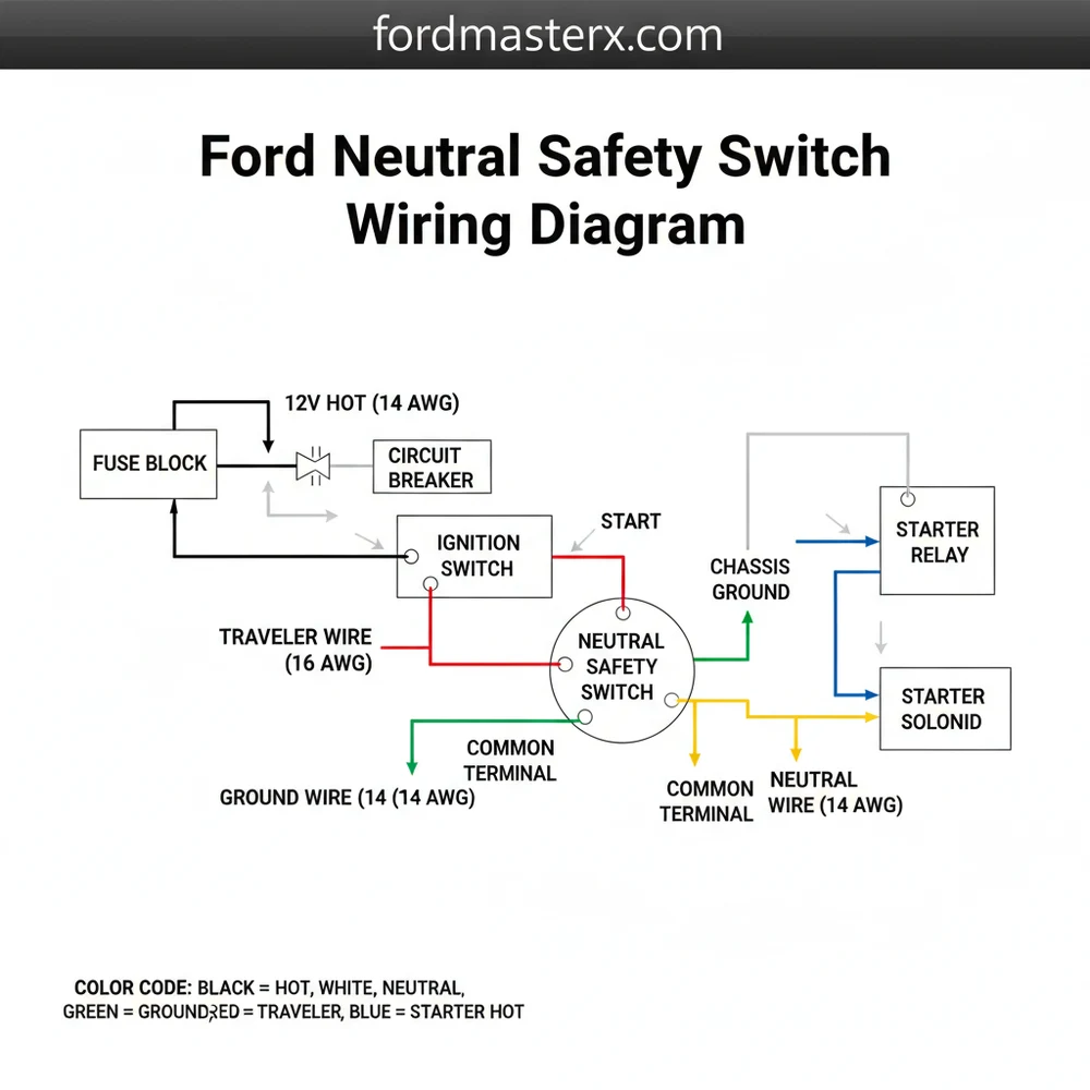
The Ford neutral safety switch wiring diagram illustrates how the ignition switch connects to the starter solenoid through the switch. It typically features a hot wire from the ignition, a neutral wire for the safety circuit, and connections to the reverse light circuit, ensuring the vehicle only starts in Park or Neutral.
📌 Key Takeaways
- The switch prevents the engine from cranking while the transmission is in gear.
- Identifying the 12V hot wire from the ignition is the first step in troubleshooting.
- Always ensure the vehicle is blocked and the parking brake is set during testing.
- Use a digital multimeter to check continuity across the common terminal.
- Use this diagram when experiencing ‘no-crank’ issues or reverse light failure.
The neutral safety switch (NSS), also known in more modern Ford vehicles as the Digital Transmission Range (TR) sensor, is a critical safety component that prevents your vehicle from starting while in any gear other than Park or Neutral. For DIY enthusiasts working on Ford trucks, Mustangs, or sedans, understanding the Ford neutral safety switch wiring diagram is the first step in diagnosing a “no-crank” condition or malfunctioning backup lights. This article provides a comprehensive breakdown of the wiring logic, component locations, and practical steps to navigate the electrical architecture of this system.
Main Components and System Features
In most Ford vehicles manufactured from the early 1990s to the mid-2010s, the neutral safety switch is located externally on the driver’s side of the transmission case, right where the shift cable attaches to the manual lever. For older Ford models with C4 or C6 transmissions, the switch might be found on the steering column or directly on the transmission housing.
The modern Ford TR sensor is more than just a simple on/off switch; it is a multi-functional component that communicates with the Powertrain Control Module (PCM). The main features found in a typical Ford wiring diagram for this system include:
- The Starter Interlock Circuit: This is the primary safety loop. It interrupts the 12V signal from the ignition switch to the starter relay unless the transmission is in Park or Neutral.
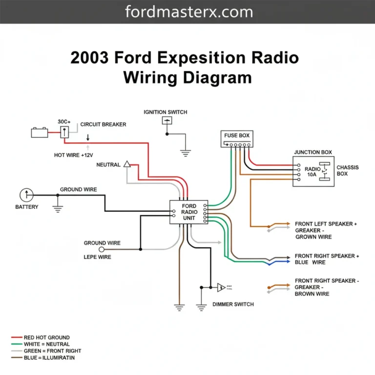
- Reverse Light Circuit: The switch also acts as the trigger for your backup lamps. When the shifter is moved to Reverse, internal contacts close to send power to the rear bulbs.
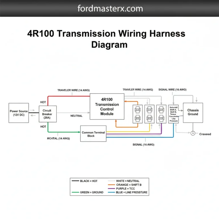
- PCM Position Signals: In “Digital” TR sensors, the switch sends a specific resistance value or voltage signal to the PCM to indicate which gear is selected (Drive, Overdrive, 2nd, 1st). This affects shift timing and torque converter lockup.
- The Wiring Connector: Most Ford TR sensors utilize an 8-pin or 12-pin weather-sealed connector. The pins are often arranged in two rows and are susceptible to corrosion due to their location underneath the vehicle.
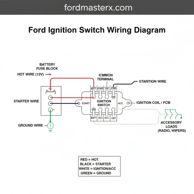
Standard Ford wire colors for these circuits often follow a specific convention, though you should always verify with a model-specific service manual. Traditionally, the Red with a Light Blue stripe wire carries the “Start” signal from the ignition to the switch, and another Red/Light Blue wire carries it out to the starter solenoid. Reverse lights are frequently powered via a Black with a Pink stripe or Dark Blue with an Orange stripe wire.
How to Use and Read the Wiring Diagram

Reading a Ford neutral safety switch wiring diagram requires understanding the flow of electricity from the battery through the ignition switch and down to the transmission. When looking at a schematic, you will see the switch represented as a box with multiple internal “wipers” or contact points.
To read the diagram effectively, follow these three paths:
- The Power Source: Identify the fuse that protects the circuit. On many F-150s and Rangers, this is a fuse in the Central Junction Box (passenger compartment fuse panel). Trace the line from the fuse to the ignition switch.
- The “Start” Path: Look for the wire labeled “Start” or “S-terminal.” Follow it to the neutral safety switch. In the diagram, you will see a dotted line or a symbol indicating that the connection is only made when the switch is in the “P” or “N” positions. If the diagram shows the line continuing to the “Starter Relay” or “Starter Solenoid,” you have found the cranking circuit.
- The Logic Ground: Modern Ford diagrams will show a ground wire (usually Black or Black/White). The TR sensor requires a solid ground to provide accurate resistance readings to the PCM. If this ground is shown as “G104” or similar, it refers to a specific grounding lug on the vehicle’s frame or engine block.
When measuring with a multimeter, the diagram tells you what to expect. For example, if the diagram shows a 12V feed on Pin 5, you should place your red probe on that pin and the black probe on a chassis ground. If the diagram shows a closed loop between Pin 1 and Pin 8 in Neutral, you should expect 0 Ohms of resistance across those pins when the shifter is in that position.
Practical Tips for DIYers

Working on the neutral safety switch can be frustrating because of its location. Use these practical tips to make the job easier and more accurate:
- Check for Physical Alignment First: Before blaming the wiring, ensure the switch itself hasn’t vibrated loose. Most Ford TR sensors have two small slots for mounting bolts. There is usually a small etched line on the plastic housing and a corresponding mark on the center rotating metal piece. These must line up perfectly when the transmission is in Neutral.
- Clean the Connector: Because the switch is exposed to road salt, mud, and water, the 10-pin or 12-pin connector often develops “green crust” (corrosion). Use a dedicated electrical contact cleaner before testing the wiring.
- Use a Back-Probe: When testing the wiring according to the diagram, do not shove your multimeter probes into the face of the connector, as this can spread the female terminals and cause a permanent loose connection. Use thin back-probe pins to slide behind the wires into the rear of the connector.
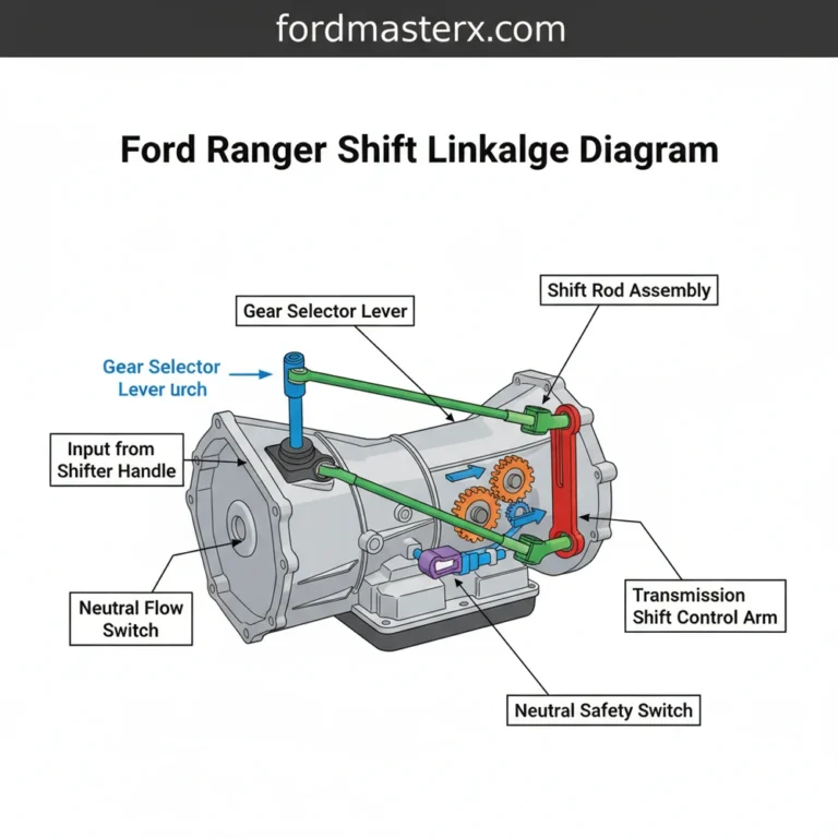
- Verify the Shift Cable: Sometimes the wiring is perfect, but the shift cable has stretched or the bushings have perished. If the cable doesn’t pull the transmission lever fully into the “Park” detent, the neutral safety switch won’t close the circuit, even if the switch itself is brand new.
Troubleshooting Common Issues
If your Ford vehicle exhibits symptoms like not starting in Park but starting in Neutral, or if the reverse lights stay on constantly, use the wiring diagram to perform these troubleshooting steps:
1. The “No-Crank” Diagnostic
Locate the Red/Light Blue wire (common on Ford) at the TR sensor. With a helper holding the key in the “Start” position, check for 12V at the input pin. If you have power going in but no power coming out of the corresponding output pin (while in Park), the internal contacts of the switch are likely burnt or the switch is out of alignment. If you have no power going into the switch, the problem lies further up the line toward the ignition switch or a blown fuse.
2. Reverse Light Failure
If your backup lights don’t work, identify the power feed wire (often Purple/Orange or White/Pink on newer Fords) and the output wire to the lamps. Jump these two pins at the connector with a fused jumper wire. If the lights turn on, the wiring to the rear of the truck is fine, and the neutral safety switch is the culprit. If they still don’t turn on, you likely have a broken wire in the harness or burnt-out bulbs.
3. “Limp Mode” or Hard Shifting
Since the TR sensor tells the PCM what gear you are in, a wiring fault can cause the transmission to shift harshly or stay in 3rd gear (Limp Mode). Use your diagram to find the “Signal Return” and “TR Signal” wires. Using a multimeter set to Ohms, check the resistance as you move the shifter through the gears. Each gear should provide a specific, steady resistance reading. If the reading “drops out” or shows “OL” (Open Loop) in certain spots, the sensor’s internal tracks are worn out.
In conclusion, the Ford neutral safety switch is a robust but exposed component. By using a wiring diagram to identify the starter interlock and reverse light circuits, you can methodically isolate whether a fault is in the switch itself, the connector, or the vehicle’s primary wiring harness. Always start with the simplest checks—fuses and physical alignment—before moving on to complex electrical testing.
Step-by-Step Guide to Understanding the Ford Neutral Safety Switch Wiring Diagram: Easy Setup Guide
Identify the specific wiring colors and pin locations using the Ford neutral safety switch wiring diagram.
Locate the switch on the transmission housing and disconnect the electrical harness connector.
Understand how the hot wire from the ignition switch delivers 12V power to the assembly.
Connect the multimeter to the ground wire and signal pins to verify circuit continuity in Park.
Verify that the traveler wire for the reverse lights receives power only when the shifter is moved.
Complete the installation by aligning the switch, tightening the mounting bolts, and testing for engine start.
Frequently Asked Questions
Where is the Ford neutral safety switch located?
On most Ford vehicles with automatic transmissions, the neutral safety switch is located on the side of the transmission case where the shift linkage attaches. In some older manual models, it may be found on the clutch pedal assembly, functioning as a clutch position sensor to prevent starting without the pedal depressed.
What does a Ford neutral safety switch wiring diagram show?
The diagram displays the electrical path between the ignition switch, the neutral safety switch, and the starter relay. It identifies the hot wire supplying power and the neutral wire that completes the safety circuit. It also includes the traveler wire configurations that provide power to the reverse light bulbs.
How many wires does a Ford neutral safety switch have?
Most Ford switches use a 4-pin or 8-pin connector. This includes the hot wire from the ignition, the output to the starter solenoid, and dual wires for the reverse light circuit. Some advanced models include a dedicated ground wire for the PCM to monitor the specific gear shift position.
What are the symptoms of a bad neutral safety switch?
Common symptoms include the engine not cranking in Park or Neutral, the engine starting in any gear, or the reverse lights failing to illuminate. If the common terminal inside the switch is corroded or misaligned, it may cause intermittent starting issues or a complete ‘no-start’ condition regardless of gear.
Can I install or replace this myself?
Yes, replacing the switch is a common DIY task. It requires basic hand tools and a jack to access the transmission. However, proper alignment is critical; the switch must be synchronized with the shift linkage so the internal common terminal makes contact only when the transmission is in Park or Neutral.
What tools do I need for testing the wiring?
You will need a digital multimeter to check for continuity and voltage, a test light for quick circuit checks, and basic hand tools like a socket set. A wiring diagram is essential to identify which pin serves as the common terminal or the traveler wire for the light circuit.