Ford Explorer 4.0 V6 Engine Diagram: Component Guide
A Ford Explorer 4.0 V6 engine diagram illustrates the layout of the SOHC or OHV power plant, highlighting the intake manifold, spark plug routing, cooling system, and belt configuration. It helps technicians locate critical sensors and ensure every component is correctly installed according to manufacturer specifications for peak vehicle reliability.
📌 Key Takeaways
- Provides a visual map for locating internal and external engine parts
- Crucial for identifying the complex timing chain system on SOHC models
- Always disconnect the battery before handling ECU or electrical connectors
- Use the diagram to verify vacuum line and spark plug wire routing
- Ideal for troubleshooting performance drops or fluid leaks
Finding a reliable ford explorer 4.0 v6 engine diagram is often the first step toward successful DIY maintenance or a complex repair project. Whether you are identifying a mysterious leak or planning a full timing chain service, having a clear visual roadmap of the engine’s internal and external components is indispensable. This guide provides a comprehensive breakdown of the 4.0L SOHC V6 engine commonly found in the Ford Explorer, helping you navigate its intricate layout. By understanding the placement of sensors, belts, and cooling components, you can perform repairs with greater confidence and precision.
Understanding the Ford Explorer 4.0L SOHC V6 Layout
The Ford 4.0L SOHC (Single OverHead Cam) V6 engine is a member of the Cologne engine family and is renowned for its specific configuration. When looking at a ford explorer 4.0 v6 engine diagram, you will notice that the engine is a longitudinal 60-degree V6. One of its most distinctive, albeit complex, features is the unique timing chain arrangement. Unlike traditional engines that place all timing components at the front, this engine utilizes a “jackshaft” system. It features a front-facing chain to drive the left cylinder head cam and a rear-facing chain to drive the right cylinder head cam.
The diagram visually separates the engine into several key zones: the upper intake system, the accessory drive, the cooling system, and the electrical sensor network. The upper intake manifold, often made of a composite plastic, sits prominently on top. Below this, you will find the fuel rails and injectors. On the front of the block, the accessory belt—also known as the serpentine belt—is routed through the alternator, power steering pump, air conditioning compressor, and the water pump. Understanding this routing is essential for any roadside repair.
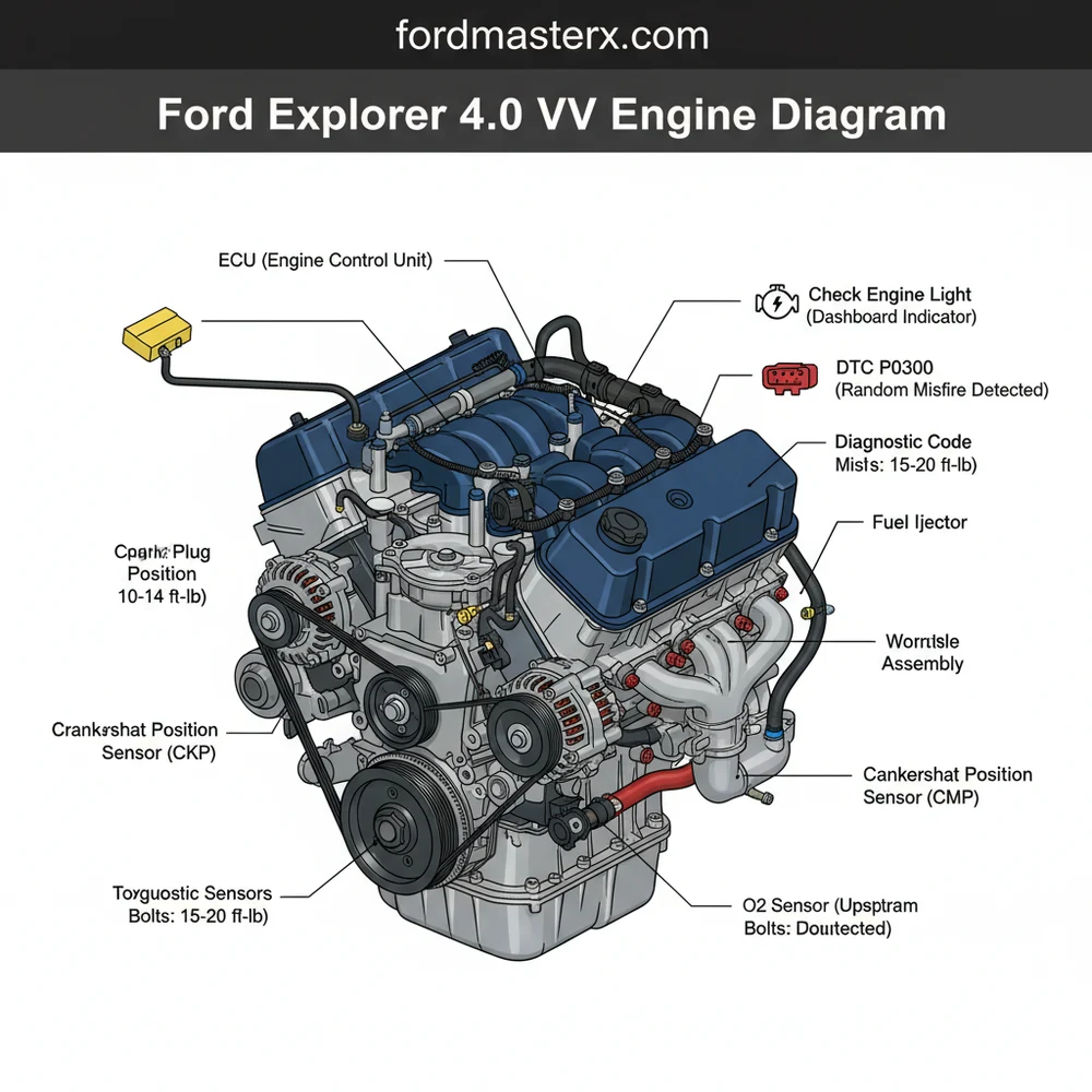
Furthermore, the diagram highlights the placement of critical management components. The ECU (Engine Control Unit) relies on data from sensors depicted in the diagram, such as the Mass Air Flow (MAF) sensor, the Throttle Position Sensor (TPS), and the various Oxygen (O2) sensors located along the exhaust manifolds. Identifying these parts through a visual aid allows you to trace wiring harnesses and identify potential points of failure that might trigger a check engine light.
Step-by-Step Guide to Reading and Applying the Diagram

Interpreting a ford explorer 4.0 v6 engine diagram requires a systematic approach. Follow these steps to translate the visual information into practical mechanical action.
Step 1: Orient Your Perspective
Before touching any bolts, match the diagram to the physical engine bay. In most diagrams, the “front” of the engine is where the radiator and accessory belt are located. Ensure you are looking at the engine from the front bumper looking toward the firewall. This prevents “mirroring” errors when identifying left vs. right cylinder banks.
Step 2: Trace the Accessory Belt Routing
Look for the continuous line representing the accessory belt. Note the direction of the tensioner pulley. If you are replacing the belt, the diagram will show you exactly which pulleys the ribbed side of the belt touches and which pulleys the smooth side touches. This is the most frequent use for an external engine diagram.
Step 3: Map the Coolant Flow
Identify the thermostat housing, which is a common failure point on this specific 4.0L engine. The diagram will illustrate the coolant flow from the radiator, through the lower hose into the water pump, and out through the upper thermostat housing. Following this path is vital when diagnosing overheating issues or air pockets in the system.
Step 4: Locate Electrical Connections and the ECU Interface
The diagram serves as a map for the electrical heartbeat of the vehicle. Locate the main wiring harness paths. By identifying where sensors connect to the ECU, you can perform continuity tests if you are dealing with a persistent diagnostic code. This is particularly helpful when a specific sensor is buried under the intake manifold.
Step 5: Identify Vacuum Lines
Vacuum leaks are notorious for causing rough idles in the Ford Explorer. Use the diagram to find the PCV (Positive Crankcase Ventilation) valve and the various vacuum hoses connecting to the upper intake. A small crack in a rubber elbow, often hidden behind the manifold, can be easily spotted if you know exactly where the line is supposed to lead.
Step 6: Check for Torque Spec References
While a diagram shows where parts go, a professional-grade diagram often includes a table for the torque spec of critical fasteners. When reassembling components like the intake manifold or the valve covers, refer to the diagram’s legend to ensure you are tightening bolts to the manufacturer’s requirements to prevent leaks or cracked housings.
The Ford 4.0L V6 SOHC engine uses a specific firing order: 1-4-2-5-3-6. This is crucial when replacing spark plug wires or checking for ignition-related misfires.
Common Issues & Troubleshooting

The Ford Explorer 4.0 V6 is a workhorse, but it has specific “weak points” that a diagram can help you troubleshoot. One of the most prevalent issues is the “timing chain rattle.” Because the engine uses multiple chains, including one at the rear of the engine, the diagram helps you identify which cassette or tensioner is likely failing based on where the noise originates.
Another frequent problem involves the thermostat housing. On many 4.0L models, the housing is plastic and prone to cracking. By using the ford explorer 4.0 v6 engine diagram, you can identify the exact bolts and sensor connections needed to swap the plastic unit for a more durable aluminum aftermarket version.
If your check engine light is illuminated, use an OBD-II scanner to pull a diagnostic code. Once you have a code, such as P0171 (System Too Lean), use the diagram to locate the MAF sensor and the intake gaskets. The visual guide helps you perform a “smoke test” or a visual inspection of the specific area indicated by the code, saving hours of aimless searching under the hood.
Always disconnect the battery before working on electrical components identified in the diagram. When working near the accessory belt, ensure the engine is completely off and keys are out of the ignition to prevent accidental start-up.
Tips & Best Practices for Engine Maintenance
To keep your Ford Explorer running smoothly for hundreds of thousands of miles, follow these professional maintenance tips:
- ✓ Use High-Quality Synthetic Oil: The timing chain tensioners on the 4.0 V6 rely on oil pressure. Clean, high-quality oil prevents sludge buildup that can clog the small passages in the tensioners.
- ✓ Inspect the PCV Elbow: This small rubber piece often fails, causing a vacuum leak. Check it every time you perform an oil change.
- ✓ Address Rumbles Early: If you hear a slight metallic rattle during a cold start, inspect the timing chain system immediately. Early intervention can prevent a total engine failure.
- ✓ Check Coolant Levels Weekly: Because the thermostat housing is a known leak point, regular level checks can save you from an expensive head gasket repair caused by overheating.
When replacing the accessory belt, take a photo of the routing on your phone even if you have a diagram. Having both a digital reference and a physical diagram ensures you won’t get stuck with a belt that’s “too long” because of a routing error.
When purchasing replacement parts, always refer back to your ford explorer 4.0 v6 engine diagram to ensure the component matches your engine’s specific configuration. While many 4.0L engines look similar, there are subtle differences in sensor connectors and hose diameters between various production runs. Investing in a set of high-quality tools, including a calibrated torque wrench and a reliable OBD-II scanner, will make your interaction with the engine diagram much more effective. By combining visual knowledge with the right tools and proactive maintenance, you can ensure your Ford Explorer remains a reliable vehicle for years to come.
Frequently Asked Questions
Where is the ECU located on a Ford Explorer 4.0 V6?
The ECU is typically located on the passenger side firewall inside the engine compartment. It is encased in a protective housing with a large wiring harness connector. Accessing it requires removing the plastic cowl cover, which is necessary for electrical diagnostics or when resolving complex computer-related performance issues.
What does this engine diagram show?
The diagram displays the orientation of the cylinder heads, intake plenum, fuel injectors, and accessory drive belt. It also identifies the location of vital sensors like the MAF, TPS, and camshaft position sensor, making it easier for owners to perform visual inspections and replace failed components without guesswork.
What are the torque specs for the intake manifold?
For the 4.0L SOHC engine, the upper intake manifold bolts generally require a torque spec of 89 lb-in. It is critical to follow a specific cross-pattern sequence to ensure an even seal. Always use a calibrated inch-pound torque wrench to prevent cracking the plastic manifold or causing vacuum leaks.
What are the symptoms of a bad camshaft sensor?
A failing camshaft sensor often triggers a check engine light and stores a specific diagnostic code in the system. Symptoms include rough idling, stalling, or a ‘crank but no start’ condition. Monitoring the signal through the OBD-II port can confirm if the sensor is sending intermittent data to the ECU.
Can I replace the spark plugs myself?
Yes, replacing spark plugs on the 4.0 V6 is a common DIY task. While the driver-side plugs are easily accessible, the passenger-side plugs may require removing the wheel well liner for better reach. Ensure the engine is cool and use a gap tool to meet factory specifications before installation.
What tools do I need for engine diagnostics?
Basic diagnostics require a standard socket set, screwdrivers, and a multimeter. However, for modern troubleshooting, an OBD-II scanner is the most important tool. It allows you to read any diagnostic code causing a check engine light, helping you pinpoint the exact sensor or circuit failure shown on the diagram.