Ford 1.0 EcoBoost Engine Diagram: Identification Guide
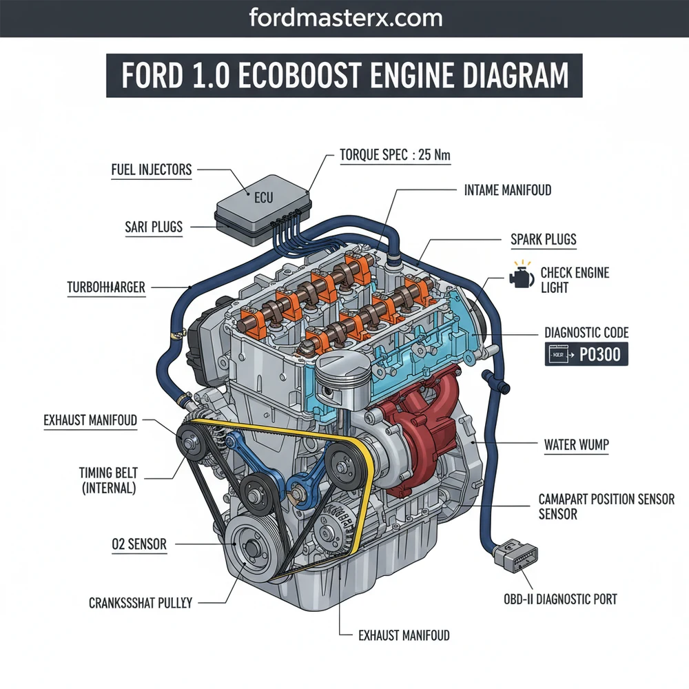
A Ford 1.0 EcoBoost engine diagram illustrates the layout of this compact three-cylinder turbocharged engine, highlighting the turbocharger, fuel system, and cooling paths. It helps owners locate specific sensors when a check engine light appears or identify the correct torque spec for critical bolts during routine maintenance and parts replacement.
📌 Key Takeaways
- Visualizing the compact three-cylinder layout for easier maintenance.
- Identifying the turbocharger and intercooler assembly locations.
- Always verify bolt tension using the correct torque spec.
- Use the diagram to trace sensor wiring back to the ECU.
- Essential for diagnosing performance issues or fluid leaks.
The Ford 1.0L EcoBoost engine, internally codenamed “Fox,” represents a pinnacle of modern downsized internal combustion engineering. Since its debut, this three-cylinder turbocharged engine has powered everything from the Ford Fiesta and Focus to the EcoSport and Transit Courier. For the DIY enthusiast, the 1.0 EcoBoost offers a unique set of challenges and rewards. Its compact design means components are tightly packed, making an accurate engine diagram and a clear understanding of its layout essential for any repair or maintenance task. Whether you are performing a simple oil change or tackling the infamous “wet belt” replacement, knowing where every sensor, hose, and bolt resides is the difference between a successful Saturday in the garage and an expensive trip to the dealership.
Main Components and Features of the 1.0 EcoBoost
Understanding the 1.0 EcoBoost begins with identifying its primary systems. Unlike traditional naturally aspirated engines, the EcoBoost relies heavily on thermal management and high-pressure induction. Here are the core components you will encounter on an engine diagram:
- The Turbocharger: Located at the front of the engine (facing the radiator), the turbo is integrated closely with the exhaust manifold. This reduces “turbo lag” by minimizing the distance exhaust gases must travel. The wastegate actuator is a common point of interest in diagrams, usually controlled by a vacuum solenoid located near the top of the valve cover.
- Integrated Exhaust Manifold: One of the most distinct features is the exhaust manifold cast directly into the cylinder head. This design allows the engine’s coolant to warm up the oil faster and keeps exhaust temperatures lower under high load, protecting the turbo.
- The “Wet” Timing Belt: Unlike most engines where the timing belt runs dry outside the engine block, the 1.0 EcoBoost uses a belt that runs in oil. This belt is located behind the front timing cover. In a diagram, you will see two belts: the primary timing belt and a smaller secondary belt driving the oil pump.
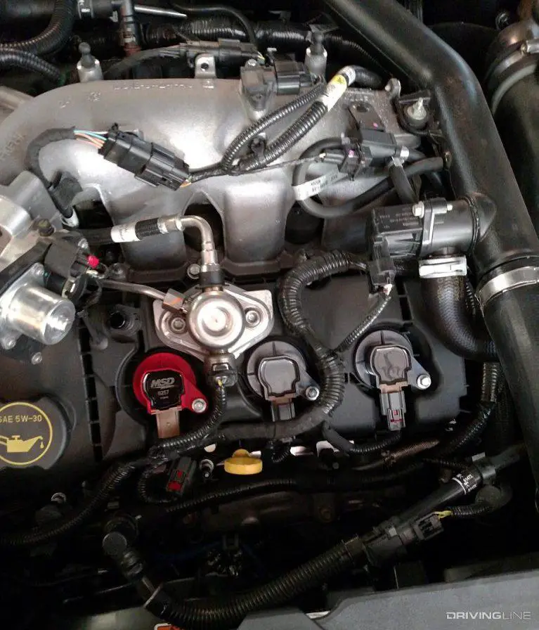
- High-Pressure Fuel System: As a Direct Injection (GDI) engine, it features a high-pressure fuel pump (HPFP) driven by the camshaft. This is typically located on the top-rear of the cylinder head, often covered by a foam noise insulator.
- Variable Camshaft Timing (Ti-VCT): The engine uses solenoids to adjust the timing of both the intake and exhaust valves. These solenoids are located on the top of the timing cover area and are frequent subjects of electrical diagrams.
How to Read and Use a Ford Engine Diagram

Ford technical diagrams follow a specific logic. When you are looking at a wiring or component diagram for the 1.0 EcoBoost, you need to understand the nomenclature used in Ford’s service literature.
Wire Color Coding
If you are troubleshooting a sensor, such as the Manifold Absolute Pressure (MAP) sensor or the Oxygen (O2) sensors, you will see abbreviations for wire colors. Common Ford color codes include:
- BK: Black
- BN: Brown
- BU: Blue
- GN: Green
- GY: Grey
- OG: Orange
- VT: Violet
- WH: White
- YE: Yellow
Often, wires are two-toned. For example, a “BN-GN” wire is a Brown wire with a Green stripe. This is critical when probing the Powertrain Control Module (PCM) harness located near the battery box.
Component Location Coding
Ford diagrams often use “C” numbers for connectors (e.g., C101) and “S” numbers for splices. The main engine harness connector (C1295) is typically located near the shock tower. When reading a vacuum diagram, look for the directional arrows; the 1.0 EcoBoost uses a complex series of check valves in the PCV (Positive Crankcase Ventilation) system to ensure the turbo doesn’t pressurize the crankcase.
Maintenance Tips for DIYers

The 1.0 EcoBoost is a “high-strung” engine, meaning it has very little margin for error regarding maintenance. Following the diagram-specific torque specs and fluid types is non-negotiable.
1. The Oil Specification Secret
Because the timing belt is a “wet belt,” using the wrong oil will cause the belt material to degrade, clog the oil pickup tube, and seize the engine. You must use oil meeting Ford specification WSS-M2C948-B (usually 5W-20). Do not use generic 5W-20 that does not explicitly list this Ford spec on the bottle.
2. Spark Plug Gapping
The 1.0L engine is sensitive to spark plug gap due to the high cylinder pressures of turbocharging. The standard gap is typically 0.7mm (0.028 inches). When referencing the ignition system diagram, ensure the coil-on-plug connectors are fully seated and the locking tabs are clicked into place, as heat vibration often loosens them over time.
3. Cooling System Bleeding
The cooling system diagram for the 1.0 EcoBoost shows a complex route including a degas bottle with two small return lines. After any cooling system repair, this engine is notoriously difficult to bleed. You should use a vacuum filling tool if possible. If manual bleeding, ensure the heater is on full blast and monitor the cylinder head temperature sensor via an OBDII scanner, as the dashboard gauge is “buffered” and won’t show overheating until it is often too late.
Troubleshooting Common Issues Using Your Diagram
Even with the best care, certain issues frequently arise with the 1.0 EcoBoost. Use your component diagram to locate and test these specific areas:
P0299: Underboost Condition
If you experience a loss of power, check the vacuum lines leading to the turbo wastegate actuator. Refer to the vacuum routing diagram and look for a cracked rubber hose near the electronic boost control solenoid (located on the side of the engine). Even a pinhole leak here will prevent the turbo from spooling correctly.
P0016 or P0017: Cam/Crank Correlation
These codes often point to the timing belt. Before tearing the engine down, use the wiring diagram to locate the Camshaft Position Sensors (CMP) and the Crankshaft Position Sensor (CKP). Check the connectors for oil intrusion. If the sensors are fine, the belt may have stretched or skipped a tooth—a serious issue requiring immediate attention.
Coolant Loss (The Degas Bottle Issue)
Early models (2012–2014) had a notorious issue where a small plastic coolant return pipe would crack. Refer to your cooling system diagram to identify the “Degas” hose. Ford released an updated part made of rubber and metal. If your diagram shows a hard plastic line running from the back of the head to the reservoir, replace it preventatively.
Oil Pressure Warning Light
If the oil light flickers, the first place to look on your diagram is the oil pressure switch (located on the block, behind the AC compressor). However, on this engine, a low pressure signal often means the timing belt is disintegrating and the debris is clogging the oil pump pickup strainer. This requires dropping the oil pan to inspect.
Conclusion
The Ford 1.0 EcoBoost is a marvel of efficiency, but it demands precision from anyone working on it. By using a detailed engine diagram to identify wire colors, component locations, and torque sequences, DIY enthusiasts can keep these engines running smoothly for years. Always remember that with this engine, “close enough” is not good enough—stick to the specifications, use the correct fluids, and always double-check your connections against the schematic before firing the engine back up.
Step-by-Step Guide to Understanding the Ford 1.0 Ecoboost Engine Diagram: Identification Guide
Identify the main engine block and cylinder head sections on the diagram.
Locate the turbocharger assembly and intake manifold components for visual inspection.
Understand how the cooling system hoses route through the integrated exhaust manifold.
Connect the OBD-II scanner to the vehicle to cross-reference codes with diagram components.
Verify that all vacuum lines and electrical connectors are seated correctly per the layout.
Complete the repair by tightening all bolts to the manufacturer’s recommended torque spec.
Frequently Asked Questions
Where is the oil filter located?
The oil filter on the Ford 1.0 EcoBoost is typically located on the front of the engine block, near the bottom. It is accessible from underneath the vehicle after removing the plastic splash shield. Using the engine diagram helps pinpoint its position relative to the oil pan and cooling lines.
What does this engine diagram show?
This diagram illustrates the layout of the 1.0L three-cylinder engine, including the integrated exhaust manifold, turbocharger system, and belt-in-oil timing system. It helps users identify sensors, fluid ports, and structural components necessary for routine maintenance, complex repairs, or performance upgrades on common Ford vehicle models like the Fiesta.
How many sensors connect to the ECU?
Numerous sensors connect to the ECU, including the MAP sensor, oxygen sensors, and crankshaft position sensor. These components monitor engine health and performance. The diagram helps you trace these electrical connections, which is vital when a specific diagnostic code indicates a sensor failure or a damaged wiring harness issue.
What are the symptoms of a bad turbocharger?
Common symptoms include a noticeable loss of power, blue smoke from the exhaust, and an illuminated check engine light. You might also hear a high-pitched whining noise under acceleration. Referencing the engine diagram allows you to locate the turbocharger and inspect the wastegate and oil feed lines for leaks.
Can I replace the timing belt myself?
Replacing the timing belt on a 1.0 EcoBoost is a highly technical ‘wet belt’ job that requires specialized tools and precision. While a diagram assists in understanding the layout, the task involves strict adherence to every torque spec and timing alignment, making it very challenging for most home mechanics.
What tools do I need for engine diagnosis?
Beyond standard hand tools, you will need an OBD-II scanner to read any stored diagnostic code from the vehicle computer. A digital torque wrench is also essential to ensure all fasteners meet factory requirements. The engine diagram guides you on where to apply these tools for components.