6.0 Powerstroke Oil Cooler Diagram: System Layout Guide
A 6.0 Powerstroke oil cooler diagram illustrates the internal structure where engine oil and coolant exchange heat. Located in the engine valley beneath the oil filter housing, this layout shows how oil flows through stacked plates while coolant passes around them, maintaining optimal thermal configuration for the lubrication system.
📌 Key Takeaways
- Visualizes the heat exchange interface between oil and coolant
- Helps identify the oil filtration and cooling stack location
- Critical for diagnosing temperature ‘delta’ spreads
- Useful for locating specific seals and gaskets during repairs
- Essential for preventing EGR cooler failure and overheating
The 6.0L Powerstroke engine is a powerhouse of diesel engineering, but its longevity depends heavily on the health of its high-pressure oil and cooling systems. Navigating the “valley” of this engine requires a clear 6.0 powerstroke oil cooler diagram to ensure every gasket, seal, and heat-exchange surface is correctly addressed during maintenance or repair. Whether you are performing a routine replacement or troubleshooting a dangerous “delta” temperature spread, understanding the internal architecture is vital for preventing catastrophic engine failure. This guide provides a comprehensive schematic overview, helping you identify critical components like the heat exchanger element, the oil filter base, and the essential high-pressure oil screen.
The oil cooler is located in the engine valley, submerged in a reservoir of oil directly beneath the intake manifold. It serves two purposes: cooling the engine oil and acting as a gateway for oil heading to the high-pressure oil pump (HPOP).
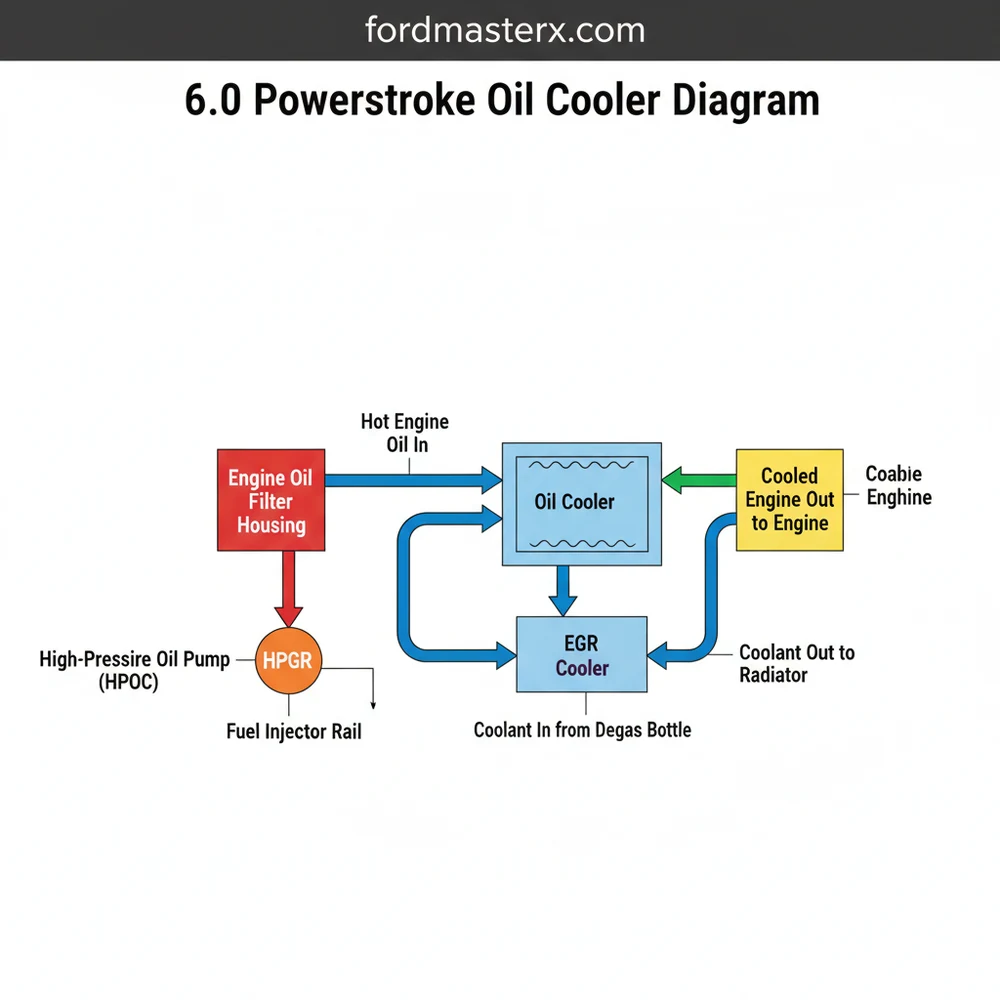
The 6.0 powerstroke oil cooler diagram illustrates a sophisticated heat exchange system housed deep within the engine’s architecture. At its core, the diagram reveals a layered structure where the oil cooler housing acts as the primary container for the heat exchanger. Inside this aluminum housing sits the stacked-plate core, which is the heart of the configuration. This element uses a counter-flow layout where engine coolant passes through narrow internal passages to absorb heat from the engine oil flowing around the plates. The diagram typically identifies the housing, the internal element, and the series of specialized Viton seals that keep the two fluids separate.
Key components found in a standard schematic include:
- ✓ The Oil Cooler Housing: A heavy cast-aluminum base that bolts directly to the engine block.
- ✓ The Oil Filter Base: This component mounts to the top of the cooler housing, directing oil through the filter before it enters the heat exchanger.
- ✓ The Heat Exchanger (Core): The multi-layered element where the actual thermal transfer occurs between oil and coolant.
- ✓ The Reservoir Screen: A fine mesh located at the bottom of the oil reservoir, designed to protect the HPOP from debris.
- ✓ The Gasket Kit: A blueprint of O-rings and perimeter seals that define the sealing surfaces of the system.
The layout shows how coolant enters through the front cover and exits through the intake manifold, while oil travels from the lubrication pump, through the cooler, and up to the filter. Most variations of the 6.0 powerstroke oil cooler diagram remain consistent across the production years, though later specifications might show slight differences in the HPOP discharge tube connection or the material used for the reservoir screen, transitioning from a plastic mesh to a stainless steel reinforced version.
[DIAGRAM_PLACEHOLDER – 6.0 Powerstroke Oil Cooler Component Layout and Flow Schematic]
Interpreting a 6.0 powerstroke oil cooler diagram is the first step toward a successful repair or upgrade. To use the blueprint effectively, you must follow a logical sequence that respects the engine’s complex layout. Because this component is buried under the intake manifold, the diagram serves as your primary map during disassembly and reassembly.
Failure to properly clean the engine valley before removing the oil cooler housing can result in dirt falling into the high-pressure oil reservoir, which will destroy the HPOP and fuel injectors.
Follow these steps to apply the diagram information to a real-world scenario:
1. System Depressurization and Draining: Begin by draining both the engine oil and the cooling system completely. Use the diagram to identify the coolant drain plugs on the engine block to ensure as much fluid as possible is removed from the valley area.
2. Component Removal: Remove the air intake, turbocharger, and intake manifold. Once these are cleared, the oil cooler housing will be visible. Refer to the 6.0 powerstroke oil cooler diagram to locate the 10 mounting bolts. These fasteners must be removed in a specific order to prevent warping the aluminum housing.
3. Housing Extraction: Carefully pry the housing upward. As you lift, consult the schematic to identify the location of the oil and coolant ports. Be prepared for a small amount of residual fluid to escape as the seals break suction.
4. Screen Inspection: Beneath the housing is the high-pressure oil pump reservoir screen. The blueprint marks this as a critical failure point. If the screen is melted or torn, it must be replaced with the updated stainless steel version to prevent debris from reaching the HPOP.
5. Cleaning the Sealing Surfaces: Use the layout in the diagram to identify every surface that requires a gasket. Use a plastic scraper and lint-free rags with brake cleaner to ensure the block and housing surfaces are pristine. Any microscopic debris can lead to a cross-contamination leak between the oil and coolant passages.
6. Heat Exchanger Replacement: Remove the old core from the housing. Install the new element using the high-quality Viton seals provided in your kit. The 6.0 powerstroke oil cooler diagram shows exactly how the blue and orange gaskets should be oriented; installing these upside down is a common mistake that leads to immediate leaks.
7. Reinstallation and Torque: Lower the assembly back into the valley. Ensure the HPOP feed tube aligns with the port as shown in the configuration. Follow the torque sequence in the diagram, typically tightening the bolts to 10 foot-pounds in a crisscross pattern to ensure even pressure across the gasket surface.
Before reinstalling the intake manifold, perform a quick pressure test on the oil cooler. This ensures that the internal seals are seated correctly before you spend hours reassembling the rest of the engine.
The most common reason for consulting a 6.0 powerstroke oil cooler diagram is a failure of the heat exchanger core. This usually manifests as a “delta” or temperature spread between the oil and coolant. If your Engine Oil Temperature (EOT) is more than 15 degrees Fahrenheit higher than your Engine Coolant Temperature (ECT) while driving at highway speeds, the system is likely clogged with silicate dropout or debris.
The schematic helps you pinpoint where the blockage occurs—usually in the tiny, accordion-style coolant passages inside the core. Another failure mode is an internal rupture. If you find oil in your coolant (looking like chocolate milk) or coolant in your oil, the diagram helps you identify the internal seals and the core itself as the primary suspects. Furthermore, the 6.0 powerstroke oil cooler diagram is essential for diagnosing external leaks at the base of the housing, which can often be mistaken for high-pressure oil pump failures or even a rear main seal leak due to how the fluid travels down the back of the block.
To ensure your 6.0 powerstroke oil cooler diagram leads to a successful and long-lasting repair, follow these professional best practices. First, never attempt to “clean” a clogged oil cooler core. The internal passages are so narrow that once they are restricted by solidified coolant, no amount of chemical flushing will fully restore the flow. Always replace the core with a new unit.
Second, upgrade your cooling system fluids. The original “Gold” coolant used in these engines is known for silicate dropout, which creates a sandpaper-like sludge that clogs the cooler’s structure. Switching to a Heavy Duty Extended Life Coolant (ELC) that meets CAT EC-1 specifications is the best way to keep the internal layout of your new cooler clean. Additionally, installing a bypass coolant filtration system will catch contaminants before they reach the oil cooler, which is the narrowest point in the entire engine’s cooling circuit.
Finally, always buy OEM Ford/Motorcraft or high-quality heavy-duty components for this specific repair. Aftermarket oil coolers often have different internal fin counts or inferior metal compositions, which can lead to poor heat transfer and immediate temperature issues even with brand-new parts. The 6.0 powerstroke oil cooler diagram assumes OEM tolerances, so sticking to factory-specified parts ensures the blueprint of your repair remains solid and reliable for miles to come.
Maintaining your 6.0L diesel requires more than just basic mechanical knowledge; it requires a deep understanding of the 6.0 powerstroke oil cooler diagram and the flow of fluids within the engine block. By mastering the schematic and following the proper installation structure, you can protect your high-pressure oil system and ensure engine longevity. With the right tools and a clear blueprint, this complex task becomes a manageable DIY project that saves thousands in professional labor costs and prevents future breakdowns.
Step-by-Step Guide to Understanding the 6.0 Powerstroke Oil Cooler Diagram: System Layout Guide
Identify the oil cooler location in the engine valley.
Locate the surrounding intake manifold and turbocharger components.
Understand how oil and coolant enter the internal structure.
Apply the diagram to verify correct seal and gasket placement.
Verify that all internal fluid passages are clear of debris.
Complete the installation by checking fluid levels and temperature deltas.
Frequently Asked Questions
Where is the oil cooler located?
The oil cooler is situated deep within the engine valley, directly beneath the oil filter housing and intake manifold. It is housed inside the oil cooler base, which serves as a reservoir for both fluids to interact within their respective channels for heat transfer.
What does this diagram show?
The diagram details the internal system configuration, showing the stacked plate design and the routing of oil and coolant. It illustrates how the fluids remain separated while heat moves from the oil to the coolant, highlighting the specific seal locations and flow paths.
How many connections does the oil cooler have?
The oil cooler assembly features primary inlet and outlet ports for both engine oil and coolant. This configuration ensures that fluid flows through the internal structure efficiently. It also includes several high-pressure O-rings and gaskets that seal the cooler to the engine block and mounting base.
What are the symptoms of a bad oil cooler?
Common symptoms include high oil temperatures compared to coolant, coolant in the oil, or oil in the degas bottle. A clogged cooler layout prevents proper heat dissipation, leading to high ‘deltas’ and potential catastrophic EGR cooler failure due to restricted coolant flow.
Can I replace this oil cooler myself?
Replacing this component is a complex task requiring the removal of the intake manifold and turbocharger. While possible for experienced DIYers, it demands a high level of technical knowledge and specific torque specifications to ensure the system is reassembled without dangerous leaks.
What tools do I need for this task?
You will need a comprehensive set of metric sockets, Torx bits, a torque wrench, and fuel line disconnect tools. Additionally, having a vacuum refill tool for the coolant and shop towels is necessary to manage fluid spills during the disassembly of the system structure.