4.0 V6 Ford Explorer 4.0 Firing Order Diagram Guide
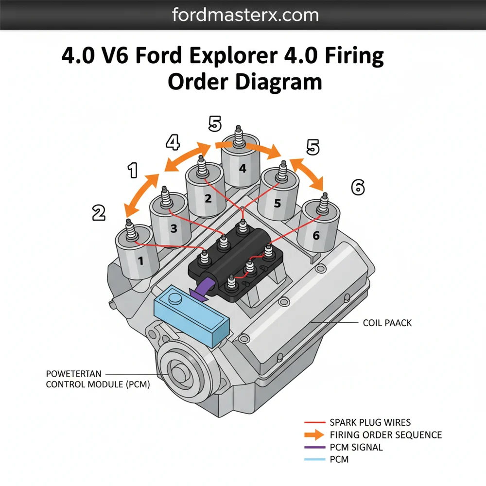
The firing order for the Ford 4.0L V6 engine is 1-4-2-5-3-6. On this engine configuration, cylinders 1-2-3 are located on the passenger side (front to back), and 4-5-6 are on the driver side. Following this layout ensures the ignition system delivers spark in the correct sequence for optimal performance.
📌 Key Takeaways
- The standard firing sequence is 1-4-2-5-3-6
- Cylinder 1 is always at the front of the passenger side bank
- Correct coil pack configuration is critical to prevent engine backfire
- Labeling wires before removal prevents timing errors
- Use this diagram when replacing spark plugs or ignition coils
If you are performing a routine tune-up or troubleshooting a persistent engine misfire, finding an accurate 4.0 v6 ford explorer 4.0 firing order diagram is the most critical step in ensuring your vehicle operates efficiently. The firing order is the precise sequence in which the spark plugs ignite the air-fuel mixture within the cylinders. Having the correct schematic prevents the accidental crossing of spark plug wires, which can lead to backfiring, poor fuel economy, or internal engine damage. This guide provides a detailed overview of the ignition system layout, helping you master the configuration of your Ford’s powerplant.
The firing order for all Ford 4.0L V6 engines—including the OHV (OverHead Valve) and SOHC (Single OverHead Cam) variants—is 1-4-2-5-3-6. While the internal mechanics differ between these engines, the ignition sequence and cylinder numbering remain consistent across the platform.
Understanding the 4.0 v6 Ford Explorer 4.0 Firing Order Diagram
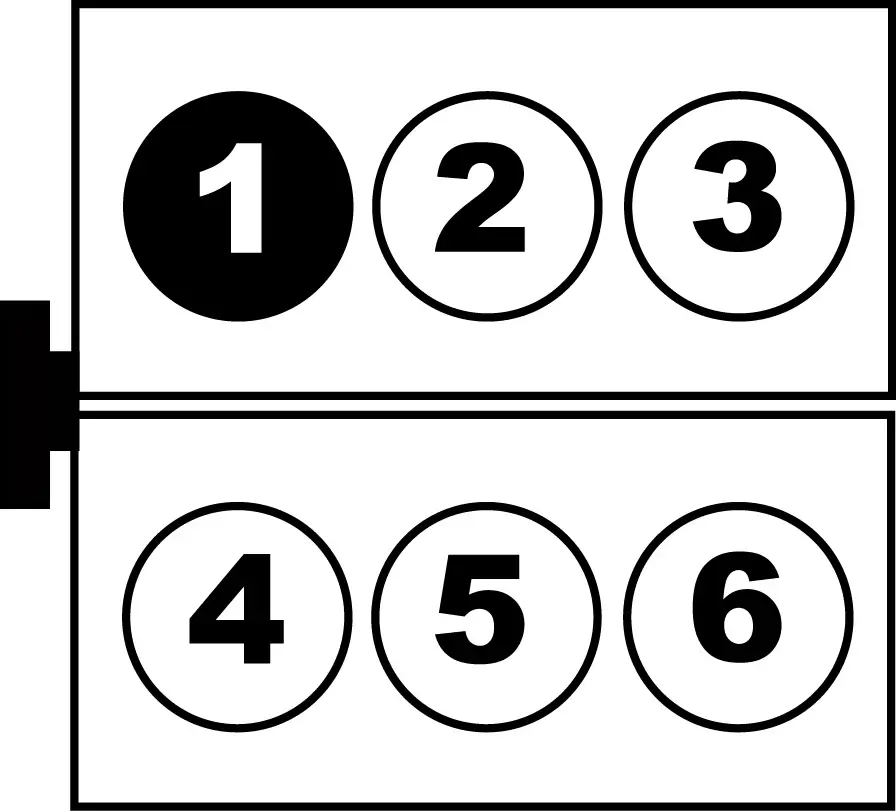
The 4.0L V6 engine uses a specific spatial layout to balance the mechanical forces of the pistons. To read the diagram correctly, you must first understand the structure of the cylinder banks. When standing at the front of the vehicle looking at the engine, the cylinders are numbered as follows: the passenger side bank contains cylinders 1, 2, and 3 (from front to back), while the driver side bank contains cylinders 4, 5, and 6 (from front to back). This configuration is the foundation of the entire ignition system.
The schematic for the coil pack is where most confusion occurs. Unlike some engines where the coil terminals match the cylinder numbers in a linear fashion, the Ford 4.0L coil pack uses a non-linear blueprint. On the standard coil pack, the terminals are usually arranged in two columns of three. Typically, the passenger side terminals correspond to cylinders 1, 2, and 3, but the driver side terminals are often arranged as 5, 6, and 4 from front to back. This “jump” in numbering is a common cause of installation errors. Referencing a visual overview is essential because the coil pack itself is often stamped with small numbers next to each terminal to indicate which cylinder it serves.
Differences in the component placement may exist depending on whether your Explorer utilizes an external ignition module or a coil-on-plug system (though the 4.0L predominantly uses a waste-spark coil pack system). Always verify the system labels on the plastic housing of the coil pack before removing any wires.
[DIAGRAM_PLACEHOLDER – Visual Representation of Ford 4.0 V6 Firing Order: 1-4-2-5-3-6. Shows Cylinder 1, 2, 3 on Passenger Side and 4, 5, 6 on Driver Side. Includes Coil Pack Terminal Mapping.]
Step-by-Step Guide to Interpreting and Applying the Diagram

Successfully applying the 4.0 v6 ford explorer 4.0 firing order diagram requires a methodical approach. Follow these steps to ensure your spark plug wires are routed correctly and safely.
- ✓ Step 1: Preparation and Safety – Ensure the engine is completely cool to the touch. Disconnect the negative battery terminal to prevent any electrical arcs while working near the ignition system. Gather your tools, including a spark plug socket, a gap gauge, and your new wire set.
- ✓ Step 2: Locate Cylinder One – Identify cylinder number one, which is the cylinder closest to the front of the engine on the passenger side. This is your “index” point for the entire configuration.
- ✓ Step 3: Map the Coil Pack – Clean the surface of the coil pack with a rag. Look for the molded numbers next to the wire towers. If the numbers are obscured by dirt or corrosion, use your schematic to identify the correct terminals for cylinders 1 through 6.
- ✓ Step 4: The One-at-a-Time Rule – To avoid confusion, never remove all the wires at once. Remove the wire for cylinder 1, replace the spark plug if necessary, and immediately install the new wire from the cylinder to the corresponding terminal on the coil pack.
- ✓ Step 5: Follow the Sequence – Move to cylinder 4 (the next in the firing order), then 2, 5, 3, and finally 6. By following the 1-4-2-5-3-6 sequence, you reinforce the layout in your mind and ensure no crossovers occur.
- ✓ Step 6: Secure the Wires – Use the plastic wire looms and clips provided on the engine structure. Keeping the wires separated is vital to prevent “inductive cross-firing,” where the electrical charge from one wire jumps to another through the insulation.
- ✓ Step 7: Final Seat Check – Press down firmly on each wire boot at both the spark plug and the coil pack. You should feel or hear a distinct “click” as the metal terminal snaps onto the post.
Mixing up the wires for cylinders 4 and 5 is the most frequent mistake on the 4.0L V6. Because these cylinders are adjacent to each other and their coil terminals are often swapped on the pack, double-check your blueprint specifically for these two connections.
Common Issues & Troubleshooting
When the ignition system is not following the prescribed 4.0 v6 ford explorer 4.0 firing order diagram, the engine will exhibit several symptoms. The most common is a “dead misfire,” where the engine shakes violently at idle and lacks power during acceleration. You may also notice a flashing “Check Engine” light, which typically indicates a catalyst-damaging misfire.
Using an OBD-II scanner can help narrow down the problem. Codes P0301 through P0306 correspond directly to cylinders 1 through 6. If you receive a P0304 and P0305 simultaneously, it is a high-probability sign that the wires for cylinders 4 and 5 have been swapped at the coil pack. The schematic serves as your primary diagnostic tool in this scenario. If the wiring matches the diagram perfectly but the misfire persists, the issue may lie within the component itself, such as a cracked coil pack housing or a fouled spark plug. Carbon tracking—tiny black lines on the porcelain of the plug or inside the wire boot—can also cause the electricity to bypass the firing order entirely.
Tips & Best Practices for a Healthy Ignition System
Maintaining the integrity of your Ford Explorer’s ignition system goes beyond just knowing the firing order. To ensure long-term reliability and peak performance, consider these professional recommendations for your next maintenance cycle.
Use a small amount of dielectric grease inside the rubber boots of the spark plug wires. This prevents the rubber from “bonding” to the porcelain of the plug over time, making future removals much easier and preventing the wire from tearing.
Always opt for high-quality OEM (Original Equipment Manufacturer) or premium aftermarket spark plugs and wires. The 4.0L V6 is particularly sensitive to spark plug gap specifications; usually, this is set to 0.054 inches, but always verify this against the emissions label under your hood. An incorrect gap can strain the coil pack, leading to premature failure of the ignition component.
Additionally, pay close attention to the layout of the wires near the exhaust manifolds. The 4.0L SOHC engine generates significant heat, which can become trapped in the engine bay. Ensure that no wires are touching the metal exhaust heat shields. If a wire rests against a hot surface, the insulation will eventually melt, leading to a grounded circuit and a recurring misfire that may only appear once the engine reaches operating temperature. Regularly inspecting the structure of your wire looms can save you from expensive diagnostic fees at a repair shop.
In conclusion, mastering the 4.0 v6 ford explorer 4.0 firing order diagram is a foundational skill for any owner looking to maintain their vehicle. By understanding the 1-4-2-5-3-6 sequence and the specific configuration of the coil pack, you can ensure your engine remains powerful, efficient, and reliable for miles to come.
Frequently Asked Questions
Where is the #1 cylinder located?
On the Ford 4.0L V6 engine, the number one cylinder is located at the front of the engine on the passenger side. This component serves as the starting point for the engine’s timing structure, with cylinders 2 and 3 following it toward the firewall on the same side.
What does this firing order diagram show?
The diagram illustrates the specific sequence in which each cylinder’s spark plug ignites. It details the physical layout of the cylinders on the engine block and the corresponding connection points on the ignition coil pack, ensuring the ignition system operates in perfect harmony.
How many wire connections does the coil pack have?
The coil pack features six high-voltage wire connections, one for each cylinder in the V6 system. Each terminal on the coil component is specifically assigned to a cylinder number, and crossing these wires will lead to immediate engine performance issues or starting failure.
What are the symptoms of a bad firing order?
If the configuration is incorrect, you will experience severe engine shaking, loud backfiring, loss of power, and a flashing check engine light. This happens because fuel is being ignited at the wrong time in the engine’s internal structure, causing harmful counter-force on the pistons.
Can I replace the spark plug wires myself?
Yes, replacing wires is a common DIY task. By following the 4.0 V6 Ford Explorer 4.0 firing order diagram, you can ensure each wire is routed to the correct cylinder. It is recommended to replace one wire at a time to maintain the proper layout.
What tools do I need for this task?
You will need a spark plug socket, a ratchet with extensions, and a gap gauge. Additionally, using masking tape to label each wire according to the system configuration is a practical way to avoid confusion during the installation of new ignition components.