The Definitive Ford Starter Solenoid Wiring Guide: Circuit Diagrams, Diagnostics, and PMGR Upgrades
The automotive starting system represents the singular moment of highest electrical stress in a vehicle’s operation. For the Ford Motor Company, the approach to managing this high-amperage event differed radically from its competitors for the better part of the 20th century. While General Motors and Chrysler largely integrated the solenoid directly onto the starter motor—placing sensitive electromechanical switching components in the high-heat environment of the exhaust headers—Ford engineers adopted a “remote relay” architecture.
This design, centered around the fender-mounted starter relay (colloquially and perpetually referred to as the “starter solenoid”), became a hallmark of Ford engineering from the 1950s through the 1990s.
This report serves as a definitive technical reference for the wiring, operation, diagnosis, and modification of this system. It goes beyond simple color codes to explore the electromagnetic principles, circuit logic, and thermal considerations that dictated this design. We will dissect the wiring harnesses of classic Mustangs, F-Series trucks, and Broncos, analyze the shift from direct-drive to Permanent Magnet Gear Reduction (PMGR) starters, and provide expert-level instruction on voltage drop testing and circuit protection.
Whether for a concours restoration or a high-performance restomod, understanding the nuanced “why” behind the “what” of the wires connecting to the starter solenoid is essential for automotive reliability.
The Semantic Distinction: Relay vs. Solenoid
To act with precision, one must define the components accurately. In strict automotive nomenclature, a relay is an electrical switch operated by an electromagnet that handles a higher current than the switch used to activate it. A solenoid is an electromechanical device that converts electrical energy into linear mechanical motion.
In the classic Ford system, the fender-mounted component is technically a heavy-duty relay. Its primary job is to bridge the high-current contacts between the battery and the starter motor. It performs no mechanical work on the starter drive gear itself; the engagement of the starter drive into the flywheel is handled by a movable pole shoe or Bendix drive within the starter motor, powered by centrifugal force or a separate internal mechanism. However, because the industry and enthusiasts universally refer to this component as the “Ford Starter Solenoid,” this report will utilize that terminology to maintain alignment with user intent and common vernacular, while acknowledging the technical distinction.
The Evolution of the Layout
The wiring that connects to the solenoid has evolved alongside engine technology.
- The 6-Volt Era: Early systems utilized positive ground and foot-pedal activation, which physically closed the contacts.
- The 12-Volt Era (1956+): The introduction of the key-turn start brought the need for the “S” terminal control circuit.
- The Resistor Era: Points ignition systems necessitated the “I” terminal for cold-start voltage bypass.
- The EFI Era: Electronic Fuel Injection and Computer Control Modules (EEC-IV) introduced the need for diode suppression to prevent voltage spikes (back EMF) from destroying silicon chips.
- The PMGR Era: The shift to modern gear-reduction starters in the 1990s changed the solenoid’s role from a primary switch to a signaling device, complicating the wiring for retrofits.
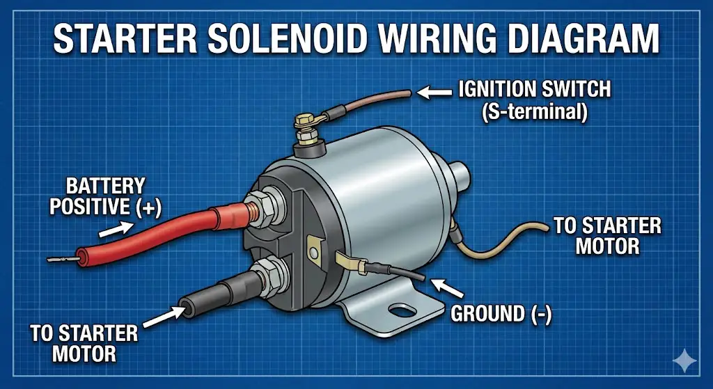
Ford Starter Solenoid Wiring Diagram
The ultimate visual guide to the fender-mounted relay. Stop guessing which wire goes where and fix that “no-start” condition today.
The “Click” of Death
When you turn your key and hear a loud single click, or nothing at all, the solenoid is your first suspect. In classic Fords (and many other vehicles), this component acts as a high-current switch, bridging the massive power from the battery to the starter motor.
Common Starting System Failures
Data aggregated from automotive repair databases showing the solenoid and wiring are more prone to failure than the motor itself.
The Wiring Map: Where Wires Go
The Ford fender-mounted solenoid (relay) typically has 3 or 4 terminals. Confusing the “Battery Side” with the “Starter Side” causes immediate electrical failure.
Battery Post (Large)
This is the “Hot at all times” side.
- Main Battery Cable: From Battery (+)
- Alternator Charge Wire: Charging output
- Fusible Links: Power to cab/fuse box
Mounting Bracket must be GROUNDED to chassis
Motor Post (Large)
Energized ONLY when cranking.
- Starter Cable: Single thick cable going down to the starter motor.
- Note: Usually NO other wires here.
Terminal Reference Guide
The “S” Terminal (Start)
Wire Color: Usually Red w/ Blue Stripe.
Receives 12V from the Ignition Switch (when in Start position) via the Neutral Safety Switch. This signal magnetizes the coil inside, closing the heavy contacts.
The “I” Terminal (Ignition)
Wire Color: Usually Brown.
Sends full 12V directly to the Coil, bypassing the ballast resistor wire. Only active during cranking to help the engine fire. Often unused on modern electronic ignition swaps.
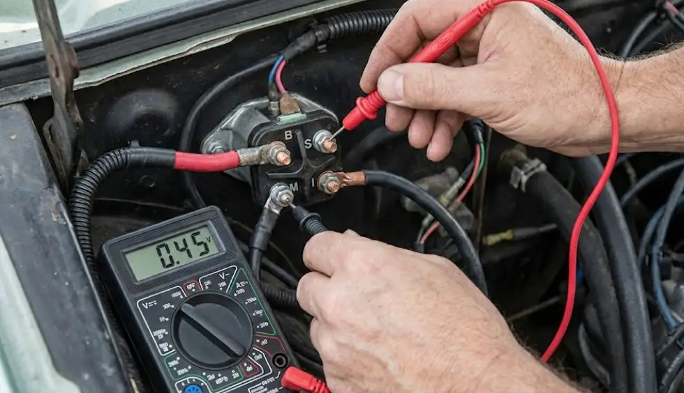
Diagnostics: The Voltage Drop Test
A simple resistance check with a multimeter isn’t enough for high-current starter circuits. You must measure Voltage Drop while cranking. High resistance = heat and slow cranking.
The 0.5V Rule
The total drop on the positive side (Battery to Starter) should never exceed 0.5 Volts. If it does, you have corrosion or a bad cable.
Ground Matters
The solenoid creates its ground through its mounting bolts. Rust on the fender wall will prevent it from clicking.
Pro Tip
If jumping the “Battery” post to the “S” post cranks the engine, your solenoid is GOOD, and your wiring/ignition switch is BAD.
© 2026 FordMasterX Infographics. Data sourced from manufacturer owner manuals.
Anatomical and Functional Analysis of the Solenoid Terminals
The standard Motorcraft SW-3 style solenoid is arguably one of the most recognizable components under a Ford hood. It typically features a Bakelite or high-temperature plastic cap, a steel mounting bracket (which serves as the ground path), and a specific arrangement of threaded studs. Identifying these terminals correctly is the first step in any wiring endeavor.
The High-Current Circuit: Terminals B and M
The two large copper studs, typically 5/16″-24 or 5/16″-18 thread, handle the immense current required to crank the engine—often peaking between 150 and 400 amps depending on compression and temperature.
The Battery Terminal (B)
This terminal serves a dual purpose: it is both the power input for the starting system and the primary power distribution hub for the entire vehicle.
- Physical Connection: It connects directly to the positive post of the battery via a heavy-gauge cable (typically 4 AWG to 1/0 AWG).
- Distribution Role: On almost all vintage Fords, this stud acts as a junction block. The main power feed to the fuse box, the headlight switch feed, and the alternator output wire (charging wire) all stack onto this single stud. This means that even when the car is off, this terminal is “hot” and carries the potential of the entire battery reserve.
- Fusible Links: The smaller accessory wires connected here are protected by fusible links—short sections of wire designed to melt under overload, sacrificing themselves to save the harness. These are the “fuses” for the main vehicle power.
The Motor Terminal (M)
This terminal is the switched output.
- State: In a resting state, this terminal is electrically dead (0V). It has infinite resistance to the Battery terminal.
- Function: When the solenoid activates, the internal copper disc slams across the B and M contacts, energizing this post.
- Connection: A single heavy-gauge cable runs from this post down to the starter motor stud. On the classic “positive engagement” starters, this wire carries the full cranking current.
The Control Circuit: Terminals S and I
The smaller threaded posts, usually #10-32, manage the logic and signaling of the system. Their correct wiring is crucial for engine ignition and safety.
The “S” (Start) Terminal
This is the activation trigger.
- Wire Color: Historically Red with a Blue Stripe (Red/Blu) in most Ford harnesses from the 1960s through the 1990s.
- Source: The Ignition Switch, via the Neutral Safety Switch (NSS).
- Mechanism: When the key is turned to the “Start” position, 12 volts are applied to this terminal. This energizes the internal electromagnetic coil. The coil’s magnetic field pulls the heavy plunger down against a return spring, bridging the B and M contacts.
- Current Draw: The pull-in coil typically draws 3 to 5 amps. This low current allows the delicate ignition switch and neutral safety switch to control the massive amperage of the starter motor without arcing or burning out.
The “I” (Ignition) Terminal
This terminal is a relic of the breaker-points era, yet crucial for proper operation of those vehicles.
- Wire Color: Historically Brown (Brn) or Brown with Yellow Stripe.
- Function: Ignition Bypass. In a standard running state, ignition coils for points systems run on approximately 7-9 volts, stepped down from 12V by a “Pink” resistance wire in the dashboard harness. This prevents the points from overheating and pitting. However, a cold engine with a cold battery cranks slower, and system voltage drops. If the coil were fed only 7 volts during cranking, the spark would be too weak to fire the fuel.
- Operation: When the solenoid engages, the “I” terminal is mechanically bridged to the high-current internal contact. It sends a full, unresisted 12 volts (or whatever battery voltage is available) directly to the coil, bypassing the resistor wire. This ensures a hot, fat spark for starting. Once the key is released, the solenoid disengages, the “I” terminal goes dead, and the engine runs on the lower voltage supplied by the ignition switch.
Visualizing the Terminal Layout
While layouts can vary slightly by manufacturer (Standard Motor Products, Motorcraft, Wells), the orientation generally follows this logic when the solenoid is mounted on the fender:
| Terminal Location | Label | Function | Wire Size | Typical Color |
| Large Left/Top | B (Batt) | Power Input | 4 AWG – 1/0 AWG | Red or Black |
| Large Right/Bottom | M (Motor) | Power Output | 4 AWG – 1/0 AWG | Black |
| Small Left (near B) | S (Start) | Trigger Input | 12 – 14 AWG | Red w/ Blue Stripe |
| Small Right (near M) | I (Ignition) | Coil Bypass | 14 – 16 AWG | Brown |
Detailed Circuit Diagrams and Wire Routing
To thoroughly answer “what wires go to the starter solenoid,” one must trace the circuit from source to load. We will analyze three distinct configurations: The Classic Points System, the Electronic Ignition System, and the Modern PMGR Retrofit.
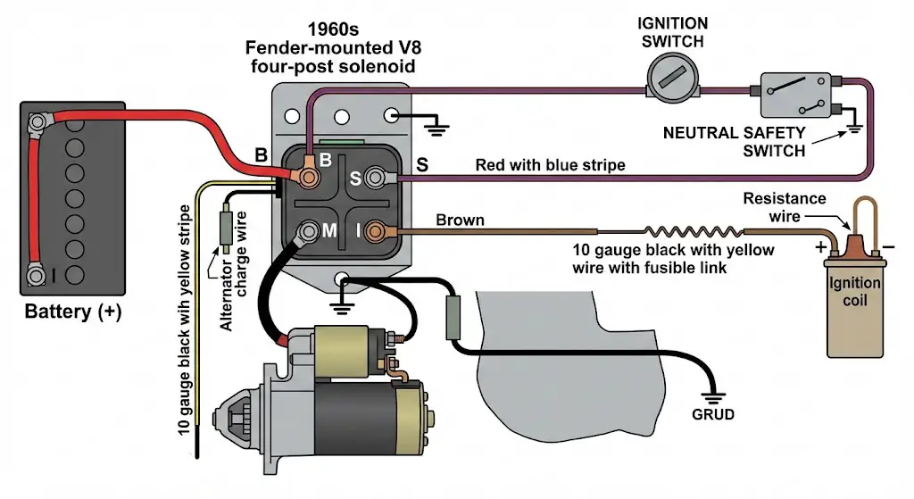
Scenario A: Classic Ford V8 (Pre-1975 Points Ignition)
This is the most complex configuration due to the ballast resistor bypass requirements.
Wiring Connections:
- Main Battery Cable (+): Connects Battery (+) to Solenoid B.
- Main Starter Cable: Connects Solenoid M to Starter Motor.
- Main Harness Feed: A 10-gauge wire (often Black/Yellow) with a fusible link connects to Solenoid B. This feeds the headlight switch, fuse box, and ignition switch.
- Alternator Charge Wire: A heavy gauge wire (Black/Orange) connects the Alternator output to Solenoid B (often via a shunt ammeter).
- Start Signal: A Red/Blue wire connects the Ignition Switch “S” post -> Neutral Safety Switch -> Solenoid S.
- Coil Bypass: A Brown wire connects Solenoid I -> positive side of the Ignition Coil (splicing into the Red/Green resistance wire).
Scenario B: Electronic Ignition (DuraSpark II / MSD)
With the advent of electronic ignition, the need for the “I” terminal diminished, although Ford retained the 4-post solenoid well into the 1980s.
- The “I” Terminal Redundancy: Modern electronic ignition modules (like the MSD 6AL or Ford DuraSpark) are designed to handle varying voltages and dwell control electronically. They do not require a ballast resistor. Therefore, on restomods using these systems, the I terminal is often left empty.
- 3-Post Solenoids: Replacement solenoids for late-80s vehicles often lack the “I” terminal entirely, featuring only S, B, and M. These are perfectly safe to use on modern-ignition vehicles but cannot be used on points-ignition restorations.
The Ground Path: The Invisible Wire
A critical “wire” that is often missing from diagrams is the ground path. The Ford solenoid is a “grounded base” design. The coil inside the solenoid that pulls the plunger down is internally grounded to the metal mounting bracket.
- The Fender Connection: The solenoid must be bolted to a clean, metal fender apron.
- The Paint Problem: Freshly painted engine bays are a common cause of non-starting. If the solenoid is bolted over thick paint, the solenoid coil cannot ground, and the solenoid will not click.
- The Solution: Use star washers to bite through the paint or run a dedicated ground wire from one of the mounting bolts to the battery negative terminal to ensure a robust connection.
Upgrading to PMGR Starters: A Wiring Paradigm Shift
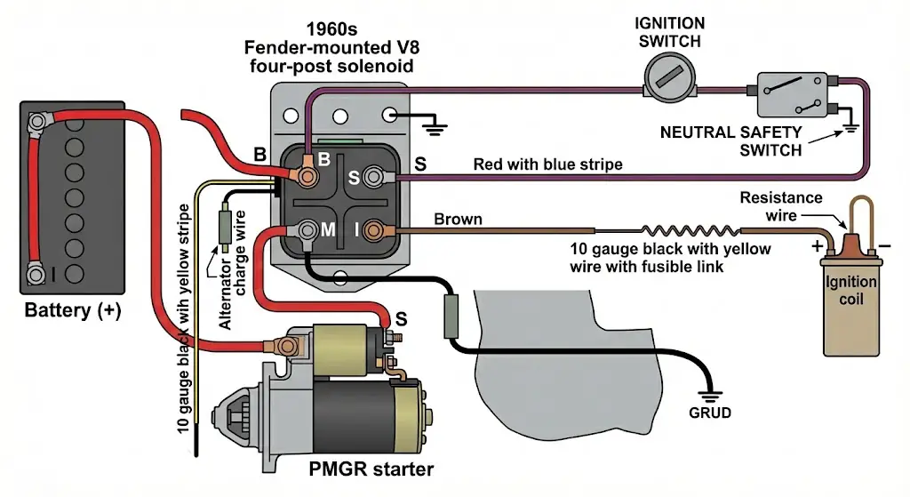
The single most significant change in Ford starter wiring occurs when upgrading from the old, heavy, direct-drive starter to a modern Permanent Magnet Gear Reduction (PMGR) starter. These starters, standard on 1992+ Fords, are smaller, lighter, and produce significantly more torque. However, they contain their own solenoid, which changes the circuit architecture fundamentally.
The PMGR Architecture Difference
- Old Starter: One thick wire. The fender solenoid switches the high current.
- PMGR Starter: Two wires (one thick, one thin). The starter-mounted solenoid switches the high current.
The “Run-On” Phenomenon
A common mistake during installation creates a dangerous condition where the starter continues to run after the engine starts.
- The Mistake: Installers often leave the heavy cable on the switched side (M) of the fender solenoid and run a short jumper wire on the starter from the main lug to the switch lug.
- The Physics: When the fender solenoid disengages, the PMGR motor is still spinning (flywheel effect). Being a permanent magnet motor, it acts as a generator (dynamo) while spinning down. This generated current back-feeds through the jumper wire into the solenoid coil, keeping the starter’s own solenoid engaged. The starter gear stays meshed with the flywheel, screaming as the engine revs up, potentially destroying the starter.
The Correct PMGR Wiring Protocol
To install a PMGR starter safely while retaining the classic look and power distribution of the fender solenoid:
- Constant Power: Move the main heavy starter cable from the M side of the fender solenoid to the B (Battery) side. This cable is now hot at all times (like a GM car).
- Trigger Wire: Run a new 12-gauge wire from the M side of the fender solenoid (which is now empty of the heavy cable) down to the small “Switch” terminal on the PMGR starter.
- Circuit Logic:
- Key to Start -> Fender Solenoid Closes.
- 12V flows from Fender Solenoid M -> New 12ga wire -> PMGR Solenoid Trigger.
- PMGR Solenoid Closes -> Draws high current from the constant hot cable.
- Advantage: The fender solenoid now acts merely as a low-current relay (handling only the 10-15 amps of the PMGR solenoid coil), drastically extending its life, while the PMGR solenoid handles the heavy lifting.
Technical Specifications: Wire Gauges and Torque
Reliability is built on specifications. Using undersized wires creates heat (I²R losses), while improper torque leads to mechanical failure.
Wire Gauge Selection Table
Voltage drop is the enemy of starting. The following table dictates the minimum wire size based on cable length (total circuit length, including ground return) and starter current draw.
| Circuit Component | Current Draw (Peak) | Length < 6 ft | Length 6-10 ft | Length 10-15 ft (Trunk Battery) |
| Starter Cable (B to M) | 150A – 250A | 4 AWG | 2 AWG | 1/0 AWG |
| S-Terminal Trigger | 3A – 5A | 16 AWG | 14 AWG | 12 AWG |
| I-Terminal Bypass | 2A – 4A | 16 AWG | 16 AWG | 14 AWG |
| Alternator Charge Wire | 60A – 130A | 8 AWG | 6 AWG | 4 AWG |
Torque Specifications
The solenoid body is fragile. The caps are traditionally Bakelite (phenolic resin) which is brittle. Overtightening nuts will crack the cap, breaking the vacuum seal and allowing moisture to corrode the contacts.
| Fastener Location | Thread Size | Recommended Torque | Notes |
| Battery Terminal (B) | 5/16″-24 | 80 – 106 in-lbs (approx 7-9 ft-lbs) | Use a backup wrench! |
| Motor Terminal (M) | 5/16″-24 | 80 – 106 in-lbs (approx 7-9 ft-lbs) | Use a backup wrench! |
| S & I Terminals | #10-32 | 15 – 20 in-lbs | Snug only. Do not crank down. |
| Mounting Bolts | 1/4″-20 | 12 – 15 ft-lbs | Ensure star washers are used for ground. |
Comprehensive Diagnostics: The Voltage Drop Test
When a Ford starter “clicks” but doesn’t crank, or cranks slowly (the “rruuh-rruuh” sound), 80% of mechanics will replace the starter or battery. 50% of the time, they are wrong. The culprit is high resistance in the connections. The only scientific way to prove this is Voltage Drop Testing.
Resistance testing (Ohms) is useless for starter circuits because a meter uses a tiny current. A cable held together by one strand of copper will read 0 Ohms but fail completely under a 200 Amp load. Voltage drop testing measures the pressure lost in the pipe while the water is flowing.
Step-by-Step Voltage Drop Procedure
Pre-Requisite: The battery must be fully charged (12.6V). Disable the ignition (unplug coil or fuel pump relay) so the engine cranks but does not start.
Test 1: The Positive Circuit Drop
- Set Multimeter to DC Volts (20V scale).
- Place Red Probe on the Battery Positive Post (the lead post, not the clamp).
- Place Black Probe on the Starter Motor Input Stud.
- Have an assistant crank the engine.
- Analysis: The meter will show the voltage lost in the wire.
- Acceptable: 0.0V to 0.6V.
- Fail: > 0.6V. This indicates a bad cable, loose crimp, or corrosion.
Test 2: The Solenoid Contact Drop
This tests the internal health of the fender solenoid.
- Place Red Probe on Solenoid B stud.
- Place Black Probe on Solenoid M stud.
- Crank the engine.
- Analysis:
- Acceptable: < 0.2V.
- Fail: > 0.5V. If the voltage drop across the solenoid terminals is high, the internal disc is pitted or carbon-fouled. The solenoid must be replaced.
Test 3: The Ground Circuit Drop (Most Common Failure)
- Place Red Probe on the Starter Motor Housing (clean metal).
- Place Black Probe on the Battery Negative Post.
- Crank the engine.
- Analysis:
- Acceptable: < 0.3V.
- Fail: > 0.5V. This indicates a bad engine ground strap, paint blocking the starter ground, or a loose negative battery terminal.
Advanced Considerations: Safety and Diode Suppression
Neutral Safety Switch (NSS) Integration
The Red/Blue wire connected to the “S” terminal does not come directly from the key. It passes through a safety interlock.
- Automatic Transmissions (C4, C6, AOD): The NSS is located on the transmission case (C4/C6) or screwing into the case (early C4). It interrupts the circuit unless the shifter is in Park or Neutral. If your car won’t crank, try wiggling the shifter while holding the key in Start. If it catches, the NSS is misaligned.
- Manual Transmissions (T5, Toploader): Late model vehicles use a clutch pedal position switch. Vintage swaps often bypass this, but for safety, a switch should be installed on the clutch pedal assembly to prevent lurching during start.
Diode Suppression for ECU Protection
In modern vehicles or restomods with EFI (like a Holley Sniper or Ford EEC-IV), the starter solenoid presents a hidden danger: Voltage Spikes.
- The Physics: The solenoid coil is an inductor. When you release the key, the magnetic field collapses, generating a high-voltage reverse spike (hundreds of volts) called “Back EMF” or “Flyback.”
- The Risk: This spike travels back up the S wire and can fry the sensitive transistors in the ECU or ignition module.
- The Fix: Use a Diode-Suppressed Solenoid (e.g., Motorcraft SW-1951-C). These units have a diode internally connected across the coil terminals. The diode acts as a one-way valve, allowing the spike to loop back to ground harmlessly rather than attacking the ECU. If running a standalone EFI, always ensure your solenoid has suppression or install an external diode (1N4007 or similar) across the coil.
Conclusion
The Ford starter solenoid system is a masterpiece of mid-century automotive engineering: simple, robust, and serviceable. However, its performance is entirely dependent on the integrity of its connections. Whether you are restoring a 1965 Mustang Fastback or building a 460-powered F-250, the rules of electricity remain constant.
Final Restoration Checklist:
- Cleanliness: Ensure all mounting points (solenoid to fender, engine ground strap) are stripped to bare metal and protected with dielectric grease.
- Protection: Fusible links are not optional. They prevent garage fires. Ensure they are present on the B terminal accessory feeds.
- Correct Parts: Do not mistake a generic “parts store” solenoid for a high-quality unit. Cheap solenoids often have steel contacts instead of copper, leading to voltage drop and welding. Look for reputable brands (Motorcraft, Standard Blue Streak) with copper terminals.
- Wire Integrity: If the Red/Blue “S” wire is brittle or cracked, replace the entire pigtail. A short here can engage the starter while driving.


