Simple 3-Wire Alternator Wiring Diagram: The Ultimate Guide (Ford & GM) 2026
The automotive charging system is the cardiovascular system of the modern vehicle, and the alternator serves as its heart. While the transition from direct current (DC) generators to alternating current (AC) alternators in the 1960s marked a pivotal shift in automotive engineering, the debate and confusion surrounding the optimal wiring configuration—specifically the choice between “one-wire” and “three-wire” setups—remains prevalent in the restomod, hot rod, and repair communities.
This report provides an exhaustive technical analysis of the 3-wire alternator system, focusing on the three most dominant architectures in the aftermarket and restoration sectors: the Ford 3G, the General Motors Delco-Remy 10SI/12SI, and the Nippondenso/Bosch import standards.
The 3-wire configuration is technically superior to the 1-wire alternative due to its utilization of remote voltage sensing, which allows the voltage regulator to compensate for resistance-induced voltage drops across the vehicle’s wiring harness. By monitoring voltage at the power distribution point rather than at the alternator’s output post, the 3-wire system ensures that critical components—ignition systems, fuel pumps, and lighting—receive the optimal 14.0V to 14.5V required for peak performance, rather than a degraded voltage that can lead to component failure or underperformance.
This document serves as a comprehensive manual for automotive technicians, engineers, and enthusiasts. It covers the fundamental physics of charging systems, detailed wiring schematics for specific alternator families, wire sizing methodologies based on thermal and electrical constraints, and advanced troubleshooting protocols for diagnosing complex issues such as parasitic draws, ground loops, and electromagnetic interference.
The Simple 3-Wire Alternator
Modernizing your classic Ford’s charging system is the single best upgrade for reliability. This guide breaks down the connections, the science, and the critical data you need to wire it right the first time.
The Diagram: Visualized
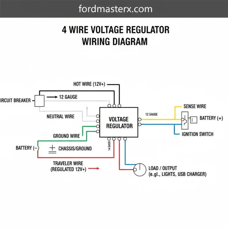
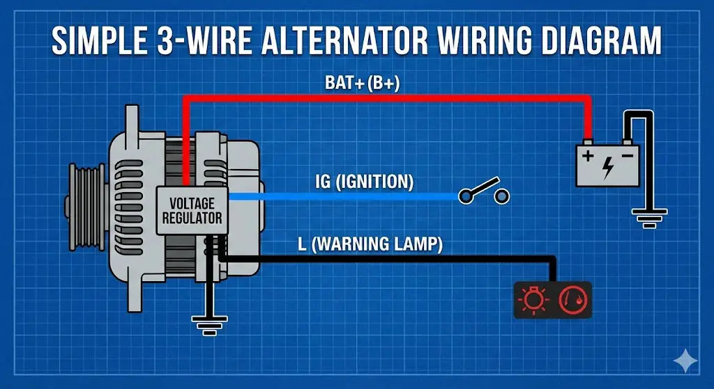
The “3-Wire” setup is universal for GM (Delco 10SI/12SI) and Ford 3G conversions. It consists of a main charge wire and a two-pin connector.
Technical Note: The “Excite” wire (Terminal #1) MUST pass through a warning light (bulb) or a 50-ohm resistor. Without this load, the alternator will not start charging, or the engine may not shut off when the key is turned (diode effect).
Amperage Output vs. RPM
Alternators do not produce full power at idle. This chart compares a standard 63A unit (10SI) vs. a high-output 130A unit (3G). Notice the 3G produces more power at idle than the 10SI does at cruise.
Wire Gauge Safety Requirements
The most common fire hazard in upgrades is retaining the stock wiring. As output increases, wire gauge (thickness) must increase (lower AWG number).
Why Installs Fail
Based on mechanics’ forum data.
Diagnostic Flow: No Charge?
Check Voltage at Battery (Engine Off)
Should read ~12.6V. If below 12.0V, charge battery first.
Check Exciter Wire (Key ON, Engine OFF)
Probe Terminal #1. Must show 12V (or slightly less if bulb is lit). If 0V, check fuse or bulb.
Check Sensing Wire (Always)
Probe Terminal #2. Must show Battery Voltage at all times. If 0V, check fusible link.
Verify Ground Path
Use multimeter (Ohms). Case of alternator to Battery Negative must be < 0.2 Ohms. Paint on brackets is the #1 killer here.
© 2025-2026 FordMasterX Infographics. Data sourced from manufacturer owner manuals.
Fundamentals of Automotive Charging Systems
The Evolution: From DC Generators to AC Alternators
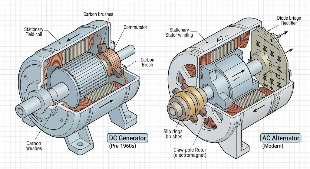
To understand the necessity of the 3-wire system, one must first appreciate the limitations of the technology it replaced. Prior to the mid-1960s, vehicles employed DC generators. These devices used a commutator—a mechanical switch—to rectify the current. While simple, generators had a fatal flaw: they produced almost no output at idle engine speeds. A vehicle idling at a traffic light would effectively run off the battery, leading to dimming headlights and stalling engines if the electrical load was too high.
The introduction of the alternator (AC generator) revolutionized this. By using a rotating magnetic field inside a stationary set of wire coils (the stator), alternators could generate significant current at low RPMs. However, because the battery requires Direct Current (DC) to charge, the Alternating Current (AC) produced by the alternator must be rectified. This is achieved through a diode bridge, a set of electrical check valves that convert AC to DC.
This transition introduced a new complexity in wiring. While a generator used an external regulator with three mechanical relays (cut-out, voltage, and current), early alternators also used external solid-state or mechanical regulators. By the 1970s and 80s, manufacturers like Delco-Remy and Ford moved the regulator inside the alternator case. This integration simplified the wiring but did not eliminate the need for external inputs to manage the alternator's behavior—specifically, when to turn on (excite) and how much voltage to produce (sensing).
The Physics of Excitation and Regulation
An alternator is technically an electromagnet. Unlike a permanent magnet generator (like those found on some motorcycles), an automotive alternator has no magnetic field when it is completely off. The rotor—the spinning part inside the alternator—is a coil of wire. To generate electricity, this rotor must first be magnetized by passing a small current through it. This initial current is called the "excitation" current.
The "Bootstrapping" Problem
In a 3-wire system, this excitation current is supplied by the vehicle's battery via the ignition switch. When the driver turns the key to "Run," voltage flows through a warning light (or resistor) into the alternator's field coil. This creates a weak magnetic field. As the engine starts and spins the rotor, this weak field induces a current in the stator coils. The alternator then becomes self-sustaining, using its own output to power the field coil.
In contrast, a 1-wire alternator relies on "residual magnetism" in the rotor core. It requires the engine to be revved to a certain RPM (often 1,200–2,000 RPM) to generate enough voltage to "wake up" the regulator. This is why 1-wire alternators often do not charge immediately upon startup, a significant disadvantage in daily-driven vehicles.
The Critical Role of Remote Voltage Sensing
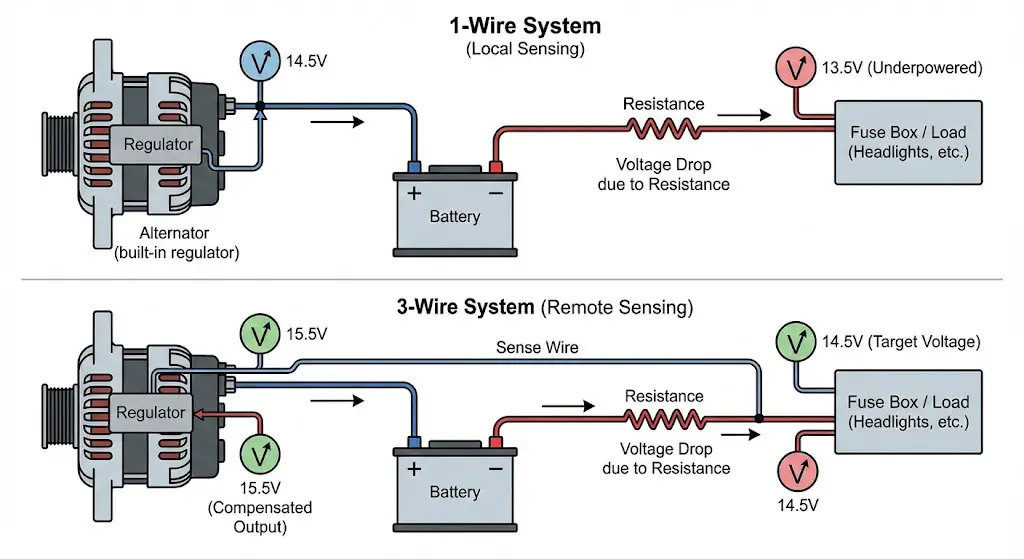
The primary engineering argument for the 3-wire system is Remote Voltage Sensing.
In any electrical circuit, wires possess internal resistance. According to Ohm's Law ($V = I \times R$), as current ($I$) flows through a wire with resistance ($R$), a Voltage Drop ($V$) occurs.
Consider a vehicle where the alternator is connected to the battery, which is then connected to a fuse box 10 feet away. If the alternator outputs 14.5V, resistance in the wires might cause the voltage at the fuse box to drop to 13.5V under heavy load (headlights, wipers, AC).
- 1-Wire System: The regulator monitors voltage at the alternator's output stud. It sees 14.5V and determines the job is done. Meanwhile, the headlights at the fuse box are dim because they are only receiving 13.5V.
- 3-Wire System: The "Sense" wire is connected physically to the fuse box. It "reports" the voltage back to the regulator. If the Sense wire detects 13.5V, the regulator "knows" the system is underpowered. It compensates by driving the alternator harder, raising the output to 15.5V (for example) to ensure the fuse box receives the target 14.5V.
Detailed Architecture of the Ford 3G Alternator
The Ford 3G (Third Generation) alternator is arguably the most popular upgrade for Ford enthusiasts, replacing the fire-prone 2G and the anemic 1G units found in Mustangs, Broncos, and F-Series trucks from the 1960s through the early 1990s. The 3G is capable of 130 Amps (standard) to over 200 Amps (aftermarket), making it a powerhouse for restomods.
The "ASI" Connector Logic
The Ford 3G utilizes a distinctive D-shaped, 3-pin connector. Understanding the pinout is critical for a successful conversion. The terminals are labeled A, S, and I.
Terminal 'A': Battery Sense (Yellow/White)
- Role: This is the voltage sensing line.
- Circuit Behavior: This wire is Always Hot (live at all times). It draws a negligible amount of current to monitor the system voltage.
- Wiring Best Practice: For optimal performance, this wire should be routed to the main power distribution point (e.g., the starter solenoid battery side or the main fuse box).
- Shortcut: In simplified installations, this can be looped directly to the B+ stud on the back of the alternator. However, this negates the benefits of remote sensing.
- Source Citation:
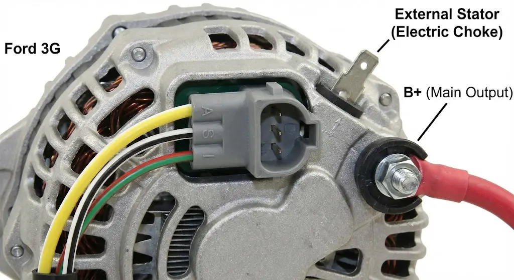
Terminal 'S': Stator (White/Black)
- Role: This terminal taps into the AC voltage generated by the stator before it is rectified.
- Internal Function: The regulator uses this signal to monitor the alternator's rotation speed.
- External Function (Electric Choke): On carbureted vehicles, this terminal provides a ~7V to ~8V signal that is used to heat the electric choke assist cap. It is crucial to note that this is not 12V; it is a half-wave rectified signal.
- Wiring: This wire connects from the 'S' pin on the 3-pin plug to the separate single spade terminal on the alternator case. If using an electric choke, the choke wire splices into this line.
- Source Citation:
Terminal 'I': Ignition / Indicator (Green/Red)
- Role: This is the "Turn On" signal.
- Circuit Behavior: This wire is Hot in Run/Start. It carries the excitation current.
- The "Idiot Light": In factory Ford wiring, this wire (Green with Red stripe) comes from the ignition switch, through the instrument cluster "AMP" or "BATT" warning light, and to the alternator. The bulb acts as a resistor (approx 15 Ohms).
- Resistor Requirement: If the vehicle does not have a warning light (e.g., a race car), a 500-ohm to 560-ohm resistor must be installed inline. Without resistance, the alternator can back-feed current to the ignition coil, preventing the engine from shutting off when the key is removed.
- Source Citation:
Ford 3G Conversion Wiring Diagram
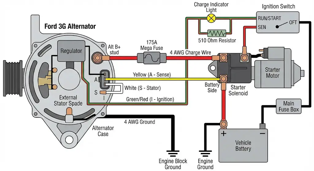
For a standard restoration (e.g., a 1966 Mustang or 1975 Bronco), the conversion from an external regulator system to a 3G internal regulator involves the following connections:
- Main Output (B+):
- Cable: 4 AWG or 2 AWG Red Cable (depending on length).
- Route: Alternator B+ Stud $\rightarrow$ 175A Mega Fuse $\rightarrow$ Starter Solenoid (Battery Side).
- Critical Note: The original factory black/yellow charge wire is insufficient for 130A and must be disconnected or bypassed.
- The Regulator Plug (ASI):
- Yellow (A): Connect to the Starter Solenoid (Battery Side) with a weatherproof ring terminal.
- White (S): Plug into the single spade connector on the side of the alternator.
- Green/Red (I): Splice into the vehicle's original Green/Red regulator wire. This wire formerly went to the "I" terminal of the external regulator.
- Grounding:
- Cable: 4 AWG Black Cable.
- Route: Alternator Case Bolt $\rightarrow$ Engine Block or Frame Rail. Relying on the mounting bracket for ground is discouraged due to paint/corrosion resistance.
Solving the V-Belt Issue on Fords
One of the most common oversights in 3G conversions is the belt drive. The 3G alternator requires significant torque to generate 130 Amps. A standard single 3/8" or 1/2" V-belt can typically only support an alternator load of 80–90 Amps before slipping and squealing.
- Solution 1 (Dual V-Belts): Acquire a dual-groove pulley for the alternator. This distributes the load across two belts, preventing slippage.
- Solution 2 (Serpentine): Convert the entire front engine accessory drive to a serpentine belt system (e.g., from a late 80s/early 90s Mustang or Explorer). This provides the best grip and reliability.
- Source Citation:
General Motors Delco-Remy 10SI/12SI System
The Delco 10SI (System Integrated) and its higher-output successor, the 12SI, are the "Small Block Chevy" of alternators: cheap, reliable, and universally adaptable. They are the standard for hot rods, tractors, and GM restorations.
The "1 & 2" Connector Architecture
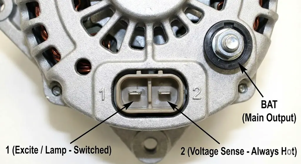
The Delco system uses a rectangular connector with two spade terminals, universally labeled 1 and 2.
Terminal #1: Excite / Lamp (Switched)
- Also Known As: R (Relay), L (Lamp).
- Role: Provides the initial field excitation to start the charging process.
- Wiring: Connects to a Switched 12V source (Ignition).
- Diode/Resistor Necessity: Like the Ford system, this terminal must have resistance. A 194-style dash bulb or a 10-ohm, 6-watt resistor (or a diode like the 1N5408) is required.
- Why? Without a diode or resistor, when the engine is turned off, the spinning alternator will continue to produce voltage that feeds back up the #1 wire, into the ignition circuit, keeping the coil energized. The engine will continue to run (diesel) until the alternator stops spinning.
- Source Citation:
Terminal #2: Voltage Sense (Always Hot)
- Also Known As: F (Field), S (Sense).
- Role: Monitors system voltage for the regulator.
- Wiring: Connects to the main power distribution block (firewall junction) or the positive battery terminal.
- The "Lazy" Loop: It is common practice to loop this wire directly to the B+ stud on the back of the alternator. While this makes for a tidy "one-wire-look" installation, it forces the alternator to regulate voltage at its own output rather than at the fuse box, reducing the efficiency of the charging system under load.
- Source Citation:
Delco 10SI Wiring Diagram for Upgrades
When retrofitting a 10SI into a vehicle originally equipped with a generator (e.g., a '55 Chevy or a tractor):
- Main Output (B+):
- Cable: 8 AWG or 6 AWG (for standard 63A units) or 4 AWG (for 100A+ builds).
- Route: Alternator BAT stud $\rightarrow$ 80A-100A Fuse $\rightarrow$ Starter Solenoid or Battery (+).
- Control Connector (1 & 2):
- Terminal 1 (Left): Connect to the "GEN" light wire from the dash. If no light exists, run a wire from the "IGN" terminal of the ignition switch with an inline 10-ohm resistor or diode.
- Terminal 2 (Right): Run to the main junction block on the firewall. This ensures bright headlights and consistent accessory performance.
- Ground:
- Ensure the alternator case is grounded to the engine block. Paint on the bracketry is the #1 cause of "Dead on Arrival" alternator installs.
Import and Universal Architectures (Denso & Bosch)
As restomods increasingly utilize modern engines like the Toyota 2JZ, GM LS (which uses Delco CS series), or European diesels, understanding the "International" wiring standards is essential.
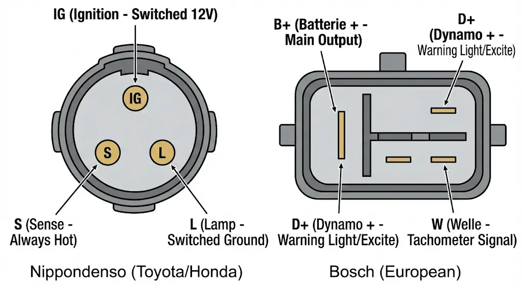
Nippondenso (Toyota/Honda) Wiring: IG, S, L
Nippondenso (now Denso) alternators are renowned for their compact size and extreme durability. They typically use a round or oval 3-pin connector.
| Terminal | Label | Name | Function & Wiring |
| B | B+ | Battery | Main Output stud. Connects to Battery (+) via high-amp fuse. |
| IG | IG | Ignition | Switched 12V. This is the primary turn-on signal for the regulator. It draws current to power the internal electronics. |
| S | S | Sense | Always Hot. Connects to Battery (+) or Fuse Box to monitor voltage. Ideally fused with a 5A or 7.5A fuse. |
| L | L | Lamp | Switched Ground. This terminal connects to the dashboard warning light. The regulator grounds this pin to turn the light on when a fault is detected. It is not the primary exciter source on many Denso units (unlike GM/Ford), though it can provide some excitation. |
Bosch (European) Wiring: B+, D+, W
Bosch alternators, found in VW, Audi, BMW, and many agricultural applications, use a different nomenclature derived from German.
| Terminal | Definition | Function |
| B+ | Batterie + | Main Output to Battery. |
| D+ | Dynamo + | Warning Light / Excitation. This is the equivalent of the GM #1 or Ford "I" terminal. It must flow through a bulb to the ignition switch. |
| DF | Dynamo Field | Used on older externally regulated units to control field strength. |
| W | Welle (Wave) | Tachometer Signal. Provides an unrectified AC signal (from one stator phase) used to drive diesel tachometers. |
Component Selection and System Engineering
Installing the alternator is only half the battle. The supporting infrastructure—wires, fuses, and connectors—must be engineered to handle the current safely.
Wire Sizing Physics: Thermal and Voltage Drop Constraints
Selecting the correct wire gauge is a safety-critical decision. Current flowing through a wire generates heat (Joules law: $P = I^2 \times R$). If the wire is too small, the resistance ($R$) is high, leading to excessive heat and potentially melting the insulation or the car itself. Furthermore, high resistance leads to voltage drop, defeating the purpose of a high-output alternator.
Table 5.1: Recommended Copper Wire Gauge for 12V Charging Systems
Values aim for <2% Voltage Drop to ensure maximum efficiency.
| Alternator Output | 0 – 6 Feet Length | 6 – 10 Feet Length | 10 – 15 Feet Length | 15 – 20 Feet Length |
| 60 – 90 Amps | 8 AWG | 6 AWG | 4 AWG | 4 AWG |
| 90 – 130 Amps | 6 AWG | 4 AWG | 2 AWG | 2 AWG |
| 130 – 160 Amps | 4 AWG | 2 AWG | 2 AWG | 1/0 AWG |
| 160 – 225 Amps | 2 AWG | 1/0 AWG | 1/0 AWG | 2/0 AWG |
Engineering Note: Always size the wire for the maximum rated output of the alternator, not the average load. If a 130A alternator is forced to output 100% capacity due to a dead battery, an undersized wire becomes a fuse.
Circuit Protection: Fusible Links vs. Mega Fuses
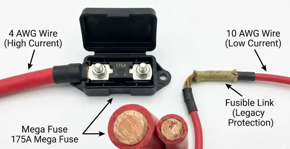
Every main charge wire must be fused at the battery end to protect the vehicle in case of a catastrophic short (e.g., in a collision).
- Fusible Links: Historically used by OEMs. A short section of wire (4 gauges smaller than the circuit wire) designed to melt under overload.
- Pros: Robust, resistant to momentary spikes.
- Cons: Difficult to identify when blown (insulation often looks intact), hard to replace on the roadside.
- Mega / ANL Fuses: The modern standard for aftermarket upgrades. Large, bolt-in fuses.
- Pros: Easy to inspect visually, easy to replace, precise amperage ratings.
- Cons: Requires a dedicated holder.
- Recommendation: Use a Mega Fuse rated at 125% of the alternator's maximum output. For a 130A alternator, a 175A fuse is ideal.
Advanced Troubleshooting and Diagnostics
Even professional builds can encounter issues. This section outlines a systematic approach to diagnosing 3-wire alternator failures.
The "Run-On" Phenomenon (Diode Fix)
Symptom: The engine continues to run after the key is turned off. Mechanism: The alternator is generating power that flows "backwards" through the Excite/Warning Light wire, feeding the ignition coil. Diagnosis: Unplug the 2-pin or 3-pin connector at the alternator while the engine is running (safety warning: ensure no loose clothing/hair near belts). If the engine dies immediately, back-feeding is the cause. Solution: Install a diode (e.g., 1N4001 or 1N5408) in the excite wire. The stripe on the diode (cathode) must face towards the alternator. This acts as a one-way check valve, allowing current to excite the alternator but preventing it from flowing back to the ignition.
Diagnosing Parasitic Draw
Symptom: Battery dies after the vehicle sits for 2-3 days.
Mechanism: The "Sense" or "Excite" wire is miswired to a constant 12V source, keeping the regulator active.
Test Protocol:
- Set Multimeter to Amps mode (10A scale).
- Disconnect Negative Battery cable.
- Place meter in series between the battery post and the cable.
- Observe draw. (Normal is 20mA–50mA for ECU/Clock memory).
- If draw is high (e.g., 3.0 Amps), unplug the alternator connector.
- If draw drops to near zero, the alternator is wired incorrectly (Ignition pin is receiving constant power) or the internal diode trio has failed.
Voltage Drop Testing
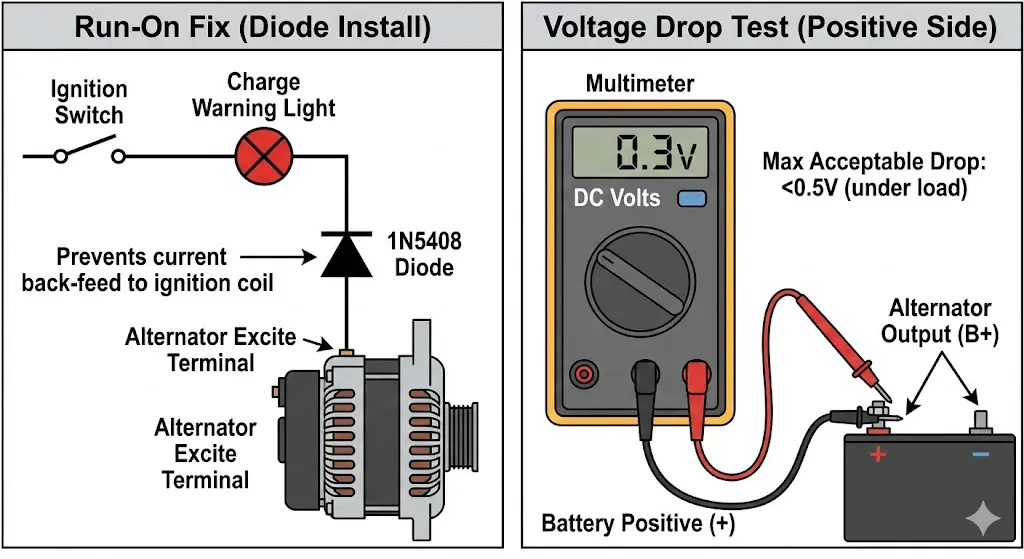
Symptom: Alternator tests "Good" on the bench (14.5V), but battery voltage is low (13.0V) while running.
Mechanism: High resistance in the Charge wire or Ground path.
Test Protocol:
- Set Multimeter to DC Volts.
- Start Engine, turn on headlights and AC fan (create a load).
- Positive Side Test: Touch one probe to the Alternator Output Stud and the other to the Battery Positive Post.
- Reading: Should be < 0.5 Volts. If it reads 1.0V or higher, the charge wire is too small, the fuse holder is corroded, or the crimps are bad.
- Negative Side Test: Touch one probe to the Alternator Case and the other to the Battery Negative Post.
- Reading: Should be < 0.2 Volts. If higher, the ground path is poor (paint on brackets, loose bolts).
Conclusion
The 3-wire alternator system represents the optimal balance of complexity and performance for automotive electrical systems. By isolating the functions of Charging (B+), Excitation (Ignition), and Regulation (Sense), it allows for a dynamic response to the vehicle's electrical demands that a 1-wire system simply cannot match.
Whether performing a Ford 3G upgrade to support modern fuel injection or installing a Delco 10SI on a vintage tractor, the principles detailed in this report—remote sensing, proper fusing, and correct wire sizing—are universal. Adherence to these engineering standards ensures a charging system that is not only powerful but also safe and reliable for the life of the vehicle.