Signal Stat 900 Wiring Diagram: Easy Setup Guide
The Signal Stat 900 wiring diagram shows how to connect the signal switch to your vehicle’s power and lighting system. It involves connecting the hot wire from the flasher to the common terminal, then routing connections to individual lamps through specific color-coded leads, ensuring a solid ground wire connection for system stability.
📌 Key Takeaways
- Main purpose is efficiently routing turn signal and hazard light power.
- The common terminal is the most critical component to identify for power input.
- Always disconnect the battery and ensure a proper ground wire connection for safety.
- Use a test light to verify the hot wire before final assembly and mounting.
- This diagram is essential during vintage truck restorations or switch replacements.
When undertaking a restoration or a lighting upgrade on a commercial truck or vintage vehicle, having a precise signal stat 900 wiring diagram is the difference between a successful installation and a frustrating electrical short. This specific turn signal switch is a heavy-duty industry standard, often utilized for its reliability and universal compatibility. Because it manages the complex interaction between turn signals and brake lights, understanding the internal circuitry and external pinouts is essential. This guide provides a comprehensive breakdown of the wiring sequence, wire color identifications, and terminal connections to ensure your lighting system functions safely and meets legal requirements. You will learn how to identify each wire, integrate the unit with your vehicle’s existing flasher, and troubleshoot common installation errors.
The Signal-Stat 900 is typically a 7-wire universal turn signal switch designed to handle both directional indicators and brake light overrides. Unlike simpler switches, this unit acts as a central hub where the brake light signal enters and is then distributed or interrupted based on the position of the lever. The diagram represents a sequence where the electrical current flows from the power source through the flasher unit and into the switch’s common terminal. From there, the internal contacts bridge the connection to the specific lamps required.
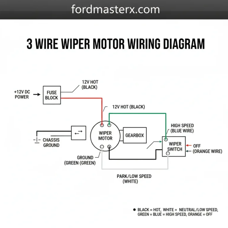
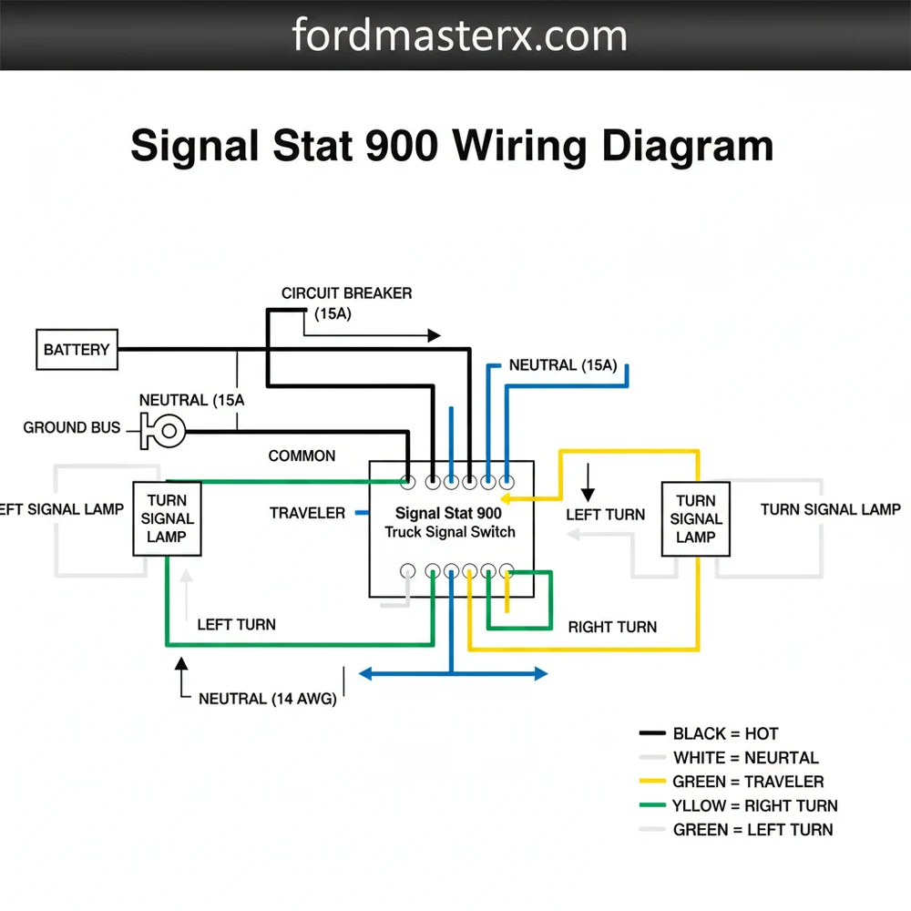
The wiring harness is color-coded to simplify the process, though variations can exist depending on the manufacturer or the age of the unit. In a standard signal stat 900 wiring diagram, you will find seven primary conductors. The blue wire is generally the feed from the flasher “L” terminal, while the white wire provides the pilot signal to the “P” terminal of the flasher to illuminate the green indicator on the switch itself. The red wire serves as the input from the brake light switch. For the output to the lamps, the yellow and green wires are designated for the left-rear and right-rear lamps respectively. The brown and black wires are dedicated to the left-front and right-front turn signals. If your specific model includes hazard functions, there may be additional leads or integrated circuitry to manage the simultaneous flashing of all four corners. Understanding these color codes is vital because a misplaced wire can lead to a “backfeed” where pressing the brake pedal causes the front turn signals to illuminate, which is a common error in universal installations.
Visualizing the Blue (Flasher), Red (Brake Switch), Yellow/Green (Rear), and Brown/Black (Front) connections.
To implement the signal stat 900 wiring diagram correctly, follow these structured steps to ensure a secure and functional installation.
Always disconnect the negative battery terminal before beginning any electrical work. This prevents accidental short circuits that could damage the switch or the vehicle’s primary wiring harness.
Step 1: Mount the Switch and Prepare the Harness
Begin by securing the Signal-Stat 900 unit to the steering column. Most units use a heavy-duty hose clamp mechanism. Ensure the switch is positioned so that the lever does not interfere with the steering wheel movement. Once mounted, strip approximately half an inch of insulation from each wire in the 7-wire harness. Use a high-quality 16 or 18-gauge wire for any extensions to ensure it can handle the current load without a significant drop in voltage.
Step 2: Identify the Power and Flasher Connections
Locate your three-prong flasher unit. The blue wire from the switch must be connected to the “L” (Load) terminal on the flasher. The white wire connects to the “P” (Pilot) terminal. The “X” or “B” terminal on the flasher itself should be connected to a fused hot wire from your fuse block. This setup ensures that the pilot light on the switch housing flashes in sync with the exterior bulbs, providing you with visual feedback.
Step 3: Integrate the Brake Light Circuit
This is the most critical part of the signal stat 900 wiring diagram. Locate the wire coming from your brake light switch (the switch activated by the brake pedal). Traditionally, this wire goes directly to the rear lamps. You must intercept this wire. The hot wire coming from the brake switch connects to the red wire on the Signal-Stat unit. This allows the switch to “interrupt” the brake signal to the rear lamps when you are signaling for a turn, preventing the brake light from overriding the blinker.
Step 4: Connect the Rear Signal and Brake Lamps
The rear lights on a 7-wire system are “shared,” meaning the same bulb filament handles both braking and turning. Connect the yellow wire from the switch to the left-rear lamp wire. Connect the green wire from the switch to the right-rear lamp wire. Ensure these connections are tight; a loose traveler wire in this section can cause intermittent flickering or dim lights.
Step 5: Connect the Front Signal Lamps
Unlike the rear lamps, the front lamps only function as turn signals (and sometimes parking lights, though that is a separate circuit). Connect the brown wire to the left-front turn signal bulb and the black wire to the right-front turn signal bulb. Since these do not involve the brake circuit, they are straightforward direct connections.
Step 6: Establish a Solid Ground
While the switch itself is grounded through the steering column clamp, the indicator light inside the housing often requires a clean ground wire connection. Ensure the metal-to-metal contact at the mounting point is free of paint and rust. If your lights are dim, it is often because the ground path lacks the necessary conductivity to return the voltage to the battery.
Step 7: Final Testing and Verification
Reconnect the battery and test each function. Check the left turn, right turn, and then hold the brake pedal down while signaling. The side that is signaling should continue to flash, while the opposite side remains steady red. Finally, check the hazard function if equipped.
Even with a perfect signal stat 900 wiring diagram, electrical systems can be temperamental. One of the most common issues is “hyper-flashing,” where the signals blink much faster than normal. This usually indicates a blown bulb or a mismatch between the flasher unit and the bulb type (such as using LED bulbs with a standard thermal flasher). If the signals do not work at all, check the hot wire leading to the flasher for 12-volt power.
Another frequent problem is the brake lights not working when the turn signals are off. This often points to a failure in the red wire connection or an internal fault in the switch’s common terminal. If you notice smoke or a burning smell, immediately disconnect the power; this indicates a short circuit, likely caused by a wire being pinched against the steering column. If you find that the front lights blink when you hit the brakes, the red wire and the front output wires have likely been swapped. If troubleshooting the basic connections does not resolve the issue, use a multimeter to check for continuity across the switch terminals. If the switch shows no continuity in the active positions, the internal brass screw contacts may be corroded or worn out, necessitating a replacement of the unit.
Most Signal-Stat 900 issues are ground-related. If the indicator light on the switch doesn’t work but the exterior lights do, check the pilot wire connection and the chassis ground at the steering column.
To ensure the longevity of your installation, always use the correct wire gauge. For a standard 12V system, 16-gauge wire is the preferred choice for the main runs to the rear of the vehicle to prevent voltage drop.
- ✓ Use Heat-Shrink Connectors: Avoid simple twist-on nuts or electrical tape. Heat-shrink butt connectors provide a waterproof seal that prevents corrosion in exposed areas.
- ✓ Apply Dielectric Grease: Use a small amount of grease on the bulb sockets and the flasher terminals to prevent moisture intrusion.
- ✓ Route Wires Carefully: Use plastic loom or zip ties to secure the harness away from moving parts like the brake pedal linkage or the steering shaft.
- ✓ Match Your Flasher: If you are using LED bulbs, you must replace the standard thermal flasher with an electronic, LED-compatible flasher to maintain the correct blink rate.
When labeling your wires, use a small piece of masking tape on each end before routing them through the dashboard. This saves hours of “tone-testing” wires later to see which one goes to the left-rear vs. the right-rear.
Following a signal stat 900 wiring diagram accurately ensures that your vehicle remains compliant with safety standards while providing the operator with clear, reliable feedback. By taking the time to understand the terminal logic—from the traveler wire paths to the common terminal inputs—you can complete a professional-grade installation that will last for years of heavy use. Proper gauge selection and secure grounding are the final touches that separate a DIY job from a master-level restoration. Regardless of the age of your truck, this wiring configuration remains the gold standard for heavy-duty directional control.
Step-by-Step Guide to Understanding the Signal Stat 900 Wiring Diagram: Easy Setup Guide
Identify the main wire colors and their corresponding functions using the Signal Stat 900 wiring diagram.
Locate the fused power source and connect the hot wire to the flasher unit’s input terminal.
Understand how the common terminal distributes power to the left and right signal circuits within the switch.
Connect the ground wire to a clean metal surface on the chassis to ensure circuit completion.
Verify that the traveler wire and signal leads are correctly routed to the front and rear lamps.
Complete the installation by testing the hazard lights and turn signals for proper flashing frequency.
Frequently Asked Questions
Where is the Signal Stat 900 unit located?
The Signal Stat 900 is typically mounted directly on the steering column of heavy-duty trucks or vintage vehicles. It is positioned within easy reach of the driver, secured by a metal clamp. This location allows the internal mechanism to interface easily with the vehicle’s main wiring harness and power source.
What does the Signal Stat 900 wiring diagram show?
The Signal Stat 900 wiring diagram illustrates the internal switch paths and external connections for turn signals and brake lights. It highlights how the hot wire from the flasher feeds the common terminal, distributing power to left and right lamps while integrating with the existing brake light circuit.
How many wire connections does the Signal Stat 900 have?
A standard Signal Stat 900 usually features seven or eight wires. These include leads for left and right front signals, left and right rear signals, a hot wire input from the flasher, a brake light feed, and occasionally a separate traveler wire or indicator ground wire depending on the specific model.
What are the symptoms of a bad Signal Stat 900 switch?
Common symptoms of a failing Signal Stat 900 include turn signals that won’t blink, lights staying on constantly, or brake lights failing to override the signal. Often, a loose ground wire or a burnt common terminal inside the housing causes these issues, leading to inconsistent electrical contact during operation.
Can I install the Signal Stat 900 wiring myself?
Yes, installing this switch is a manageable DIY task for those with basic electrical knowledge. By following the Signal Stat 900 wiring diagram, you can identify the neutral wire or ground points and map out the signal paths. Using a multimeter helps verify connections before securing the unit to the column.
What tools do I need for Signal Stat 900 wiring?
You will need a wire stripper, crimping tool, and a digital multimeter or test light to verify the hot wire. Additionally, a screwdriver set is required to mount the switch to the steering column. Heat shrink tubing and electrical tape are recommended to protect the traveler wire and other connections.