The Engineering and Service Architecture of Ford Explorer Anti-Theft Systems: A Comprehensive Diagnostic and Remediation Treatise (1991–2026)
The Ford Explorer, a seminal vehicle in the development of the Sport Utility Vehicle (SUV) segment, has undergone a radical evolution in vehicle security architecture over its three-decade production history. From rudimentary perimeter alarms in the early 1990s to the cloud-connected, bi-directional encrypted systems of the 2020s, the Explorer’s security measures reflect the broader automotive industry’s battle against theft. However, this increasing sophistication has introduced a complex array of failure modes that often leave legitimate owners stranded.
The Passive Anti-Theft System (PATS), commercially known as SecuriLock, represents the core of this architecture. Unlike active alarm systems that rely on noise to deter theft, PATS utilizes Radio Frequency Identification (RFID) to immobilize the engine’s fuel and ignition systems. This report provides an exhaustive technical analysis of the Ford Explorer’s anti-theft systems across six vehicle generations. It integrates data from technical service bulletins, aftermarket engineering analysis, and field diagnostics to provide a definitive guide on the operation, diagnosis, and remediation of system lockouts.
Key findings indicate that while software logic “glitches” are a common source of immobilization—often rectifiable via manual reset procedures like the “10-minute cycle”—hardware degradation remains a significant factor in aging fleets. Specifically, the inductive transceiver ring in the steering column and the decay of electrical grounding points are primary failure vectors.
Furthermore, the modern integration of the Body Control Module (BCM) and Gateway Module (GWM) has shifted the repair paradigm from mechanical replacement to software re-initialization, necessitating a new tier of diagnostic tools. This report also outlines the specific interaction between vehicle battery health and security module logic, demonstrating that voltage instability is the leading cause of “false” theft events.
FordMasterX
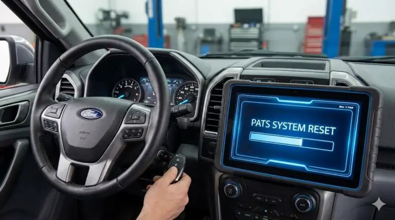
Is Your Ford Explorer Immobilized?
A rapidly flashing anti-theft light means your Passive Anti-Theft System (PATS) has locked the engine. Don’t panic. Whether it’s a dead key fob or a system glitch, you can reset it right now without a tow truck.
The Symptom
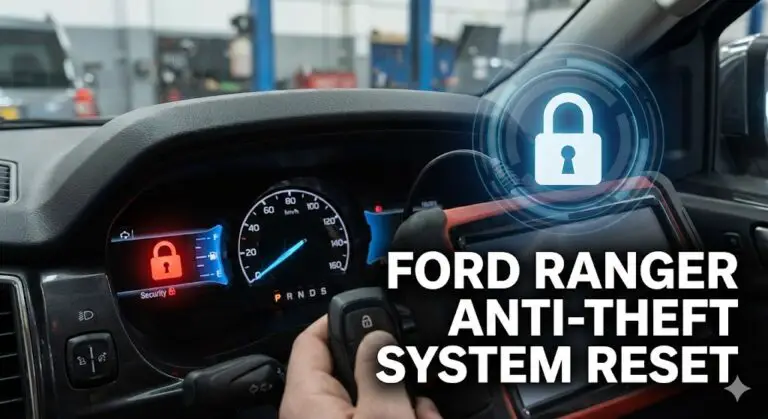
Rapidly flashing red padlock icon or dashboard light when turning the key.
The Cause
PATS / SecuriLock cannot recognize your key’s transponder signal.
The Fix
4 proven reset methods ranging from 2 minutes to 15 minutes.
Method Effectiveness & Speed
Before we dive into the steps, here is a breakdown of which methods work best based on user reports and the time investment required for each.
User-Reported Success Rates
Percentage of successful resets by method type
Insight: The “Door Lock Cylinder” method is often the most overlooked but highly effective mechanical override for the alarm.
Time Investment Required
Minutes required to complete the procedure
Insight: The Battery Disconnect is a “Hard Reset” and takes the longest because the capacitors must fully discharge.
4 Ways to Reset Your Anti-Theft System
1 The Key Fob Trick
Often, the system just needs a “handshake” reminder. This works best if the alarm was triggered by a door sensor glitch.
Step 1
Hold ‘Panic’
Step 2
Wait 5 Seconds
Step 3
Press ‘Unlock’ 2x
2 The Driver’s Door Cylinder
If the fob battery is dead, the physical lock cylinder has a switch that can disarm the factory alarm.
- 1. Exit the vehicle and close all doors. Ensure the hood and trunk are latched.
- 2. Insert your physical key into the driver’s side door lock.
- 3. Turn the key to Unlock, then hold for 1 second.
- 4. Turn to Lock, then back to Unlock. This sequence signals authorized entry to the BCM (Body Control Module).
3 The Ignition Sequence
For Ford Explorers where the key is not recognized (fast flashing light), you need to force the system into programming mode to re-verify the chip.
Dashboard Indicator
PADLOCK ICON
Must go from flashing -> solid -> off
4 The Hard Battery Reset
If software glitches are to blame, cut the power.
⚠️ Procedure:
Disconnect the Negative (-) battery terminal (Black cable). Wait fully 15 minutes to drain capacitors. Reconnect and tighten. This forces all modules (PCM, BCM) to reboot.
Why Did This Happen?
The Ford Passive Anti-Theft System (PATS) uses an RFID chip inside your key head. A transceiver ring around your ignition reads this chip. If the data doesn’t match the ECU’s stored codes, the fuel pump is disabled.
Most failures aren’t actual theft attempts, but simple hardware failures or communication errors.
Expert Tip
Do not have other large keys or RFID tags (like gym passes or speed passes) on the same ring. They can interfere with the signal.
Common Triggers of Anti-Theft Lockouts
Based on mechanic service logs
Theoretical Framework: The Evolution of Automotive Identity
To effectively diagnose and reset the anti-theft system of a Ford Explorer, it is imperative to understand the underlying engineering philosophy that dictates its operation. The system is not merely a switch; it is a networked cryptographic exchange.
The Philosophy of Immobilization
In the early automotive era, security was mechanical. A cut key rotated a tumbler, which mechanically actuated an ignition switch. This could be easily bypassed by “hot-wiring”—physically connecting the battery wire to the ignition wire. The industry’s response was the “Immobilizer.” The concept is simple but profound: the vehicle must possess a digital identity verification system that is independent of the mechanical lock.
Ford’s implementation of this, the Passive Anti-Theft System (PATS), separates the function of “Access” (unlocking the car) from “Authorization” (starting the car). A driver might mechanically unlock the door and turn the ignition cylinder, but without digital authorization, the Powertrain Control Module (PCM) will refuse to fire the fuel injectors.
The Physics of RFID in Automotive Security
The core technology powering PATS is Low-Frequency (LF) RFID.
- The Exciter (Transceiver): Located around the ignition lock cylinder (or in the Push-Start button assembly), this is a copper coil antenna. When the driver initiates a start sequence, the module passes an alternating current through this coil, generating an electromagnetic field at 134 kHz.
- The Transponder (Key): Embedded in the plastic head of the key is a small capsule containing a microchip and a copper coil. It contains no battery. Through the principle of magnetic induction, the field from the transceiver induces a current in the key’s coil, powering the chip.
- The Modulation: Once powered, the key modulates the magnetic field to transmit its unique hexadecimal identifier back to the transceiver. This is known as “Backscatter Modulation.”
- The Encryption:
- PATS 1 (1996-1997): Used a fixed code.
- PATS 2/SecuriLock (1998-2010): Utilized Texas Instruments 4D63 transponders with 40-bit or 80-bit encryption, employing a “Challenge-Response” mechanism where the vehicle sends a random number (nonce), and the key must encrypt it correctly.
- Intelligent Access (2011+): Uses AES-128 encryption with bi-directional UHF and LF communication.
The Network Topology
The security decision is never made by a single component. It is a consensus reached by multiple modules communicating over the Controller Area Network (CAN) bus.
- Transceiver: Reads the Key ID.
- Cluster/BCM: Receives the ID, checks its “Whitelist.” If valid, it sends an encrypted “Go” message to the PCM.
- PCM: Verifies the “Go” message. If verified, it grounds the starter relay and pulses the fuel injectors. Implication: A failure in the CAN bus wiring (e.g., a severed twisted pair) will prevent the “Go” message from reaching the PCM, resulting in a theft lockout even if the key is valid.3
Historical Architecture Analysis: Generation by Generation
The Ford Explorer has seen six distinct generations, each with a unique security architecture. Identifying the generation is the first step in diagnosis.
Generation 1 (1991–1994): The Perimeter Alarm Era
The first-generation Explorer did not feature an engine immobilizer in the modern sense. It utilized a Perimeter Anti-Theft System.
- Operational Logic: The system monitored the door ajar switches, hood pin, and liftgate latch. If a breach was detected without the door cylinder being rotated (which closes a disarm switch), the system would sound the horn and flash the lights. Critically, it engaged a “Starter Interrupt Relay” preventing the engine from cranking.
- Component Location: The brains of this system were often located in a dedicated module in the rear quarter panel (driver’s side), near the jack storage.
- Common Failure: The door lock cylinder switches would wear out, failing to send the “Disarm” signal when the owner unlocked the door with the key.
- Reset Procedure: Since there is no chip to read, the reset is mechanical.
- Unlock the liftgate or passenger door with the key.
- Cycle the key in the driver’s door to the “Unlock” position and hold for 2 seconds.
- If the alarm persists, locate the “Anti-Theft” hood switch and ensure it is not bent or corroded.
- Permanent Disable: Grounding the “Purple/Yellow” wire at the alarm module is a known field bypass, though it compromises security.
Generation 2 (1995–2001): The Dawn of PATS
This generation introduced the transponder key, fundamentally changing the reset procedure.
- 1995-1997 (PATS I): Featured a standalone PATS module located behind the dash, often near the passenger airbag. The key had no “Ford” logo on the head, just a small plastic cap covering the chip.
- 1998-2001 (PATS II / HEC): The security logic moved into the Hybrid Electronic Cluster (HEC). The instrument cluster became the “Gateway.”
- Critical Insight: If the instrument cluster fails (a common issue due to cold solder joints on the circuit board), the vehicle will not start because the PATS logic is dead.
- The “Theft” Light: Located on the cluster. Rapid flashing indicates a PATS failure.^9^
- Reset/Programming: This generation requires one working key to add a second key (on early models) or two working keys to add a third (on later models). If all keys are lost, the PCM must be “parameter reset” using a scan tool like FORScan or IDS.
Generation 3 & 4 (2002–2010): The CAN Bus Integration
These models represent the peak of “traditional” PATS issues. The system migrated fully to the CAN bus, making it sensitive to electrical noise.
- Architecture: The Instrument Cluster remains the master node. It communicates with the PCM via the Standard Corporate Protocol (SCP) or CAN.
- The Transceiver Ring (Part 1L5Z-15607-AA): This component is notorious for internal winding failure. The fine copper wires inside the plastic ring around the ignition break, causing an intermittent Code B1600 (No Key Signal).
- Symptom: The car starts fine 90% of the time, but occasionally the theft light flashes rapidly and the engine cranks but won’t fire.
- Remote Start Interference: Installers of aftermarket remote starters (Viper, Compustar) often splice into the PATS transceiver wires (White/Orange and White/Green) to install a bypass module. Over time, these crimp connectors loosen, creating high resistance that corrupts the data signal.
- Diagnostic: If a modified vehicle has PATS issues, the first step is to inspect the wiring under the steering column shroud.^3^
Generation 5 (2011–2019): Intelligent Access & BCM Dominance
The Explorer moved to a unibody platform and introduced “Intelligent Access” (Push-Button Start).
- PEPS (Passive Entry Passive Start): The vehicle has multiple LF antennas (in the console, door handles, and bumper) to triangulate the key fob’s position. The fob must be inside the cabin to authorize a start.
- Key Fob Sleep Mode: Modern fobs enter a sleep mode to save battery. If the fob is stationary for too long, it may stop transmitting. Shaking the fob can wake it up.
- The Backup Slot: Because the fob uses a battery to transmit the UHF signal, a dead fob battery can leave the user stranded. Ford engineered a “Backup Slot” (Immobilizer Reader).
- Location (2011-2015): Inside the center console utility bin or the front cupholder.
- Location (2016-2019): Often under the rubber mat in the center console storage bin.
- Physics: Placing the fob in this slot places the transponder chip directly next to a hidden inductive coil, allowing the car to power the chip passively (like the older keys) and start the engine even with a dead fob battery.
Generation 6 (2020–Present): The Connected Security Cloud
The modern Explorer utilizes the Ford Digital Architecture (FDA), where security is handled by the Gateway Module (GWM) and authenticated potentially via the cloud (Phone-as-a-Key).
- BCM-PCM Handshake: The security exchange is high-speed and encrypted with AES-128. Manual resets are less effective here.
- OTA Updates: Over-the-Air updates can occasionally hang or fail, leaving the security modules in a “bootloader” mode where they cannot authenticate the key. A “Global Reset” (Battery disconnect) is often the only way to reboot the modem and GWM.
- Hood Switch Vulnerability: The 2020+ Explorer has a highly sensitive hood ajar switch integrated into the latch. If this switch misaligns, the BCM believes the hood is open (a theft risk) and will disable remote start features and trigger the alarm randomly.
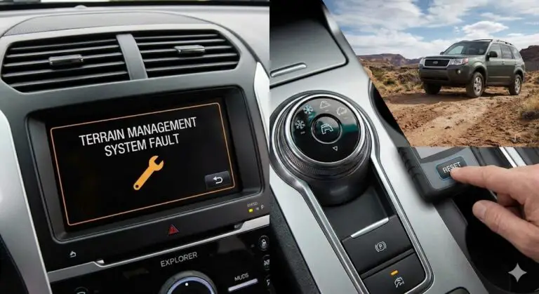
Diagnostic Pathology: Decoding the “Theft” Light
The “Theft” indicator on the dashboard (often a red padlock or a red dot) is the primary interface for the vehicle to communicate its security status. It acts as a primitive diagnostic tool.
Normal Behavior
- Key OFF: The light flashes once every 2 seconds. This indicates the system is armed and monitoring the perimeter.
- Key ON: The light glows solid for 3 seconds (proving the bulb works) and then extinguishes. This indicates the key has been read and accepted.
Failure Mode 1: Rapid Flashing (The “Lockout”)
If the light flashes rapidly (2-3 times per second) immediately upon turning the ignition to ON:
- Meaning: The Transceiver has failed to read a valid key code.
- Implication: The PCM has disabled the fuel injectors and spark. The starter relay may also be disabled (depending on year).
- Likely Causes:
- Unprogrammed Key: The key has the wrong chip or is not in the whitelist.
- Bad Transceiver: The antenna ring is open/shorted (Code B1600).
- Transponder Failure: The chip inside the key is cracked (common if keys are dropped).
- Interference: A second key, a toll pass, or a metallic key tag is blocking the signal.
Failure Mode 2: Solid Red Light (System Error)
If the light stays solid red for more than a minute while the key is ON:
- Meaning: The PATS module or PCM has detected a system integrity fault.
- Likely Causes:
- Power Loss: A blown fuse supplying the PCM or Cluster.
- Data Link Failure: The CAN bus wires between the Cluster and PCM are cut or shorted.
- Corrupted Memory: The PCM’s EEPROM has lost the security ID data (often caused by dead battery jump-starting with high voltage spikes).
Diagnostic Trouble Codes (DTCs)
Using a scan tool is the only way to be certain.
- P1260: “Theft Detected – Vehicle Immobilized.” This code is generic. It just confirms the engine was stopped by PATS.
- B1600: No PATS Transceiver Signal. (Hardware failure).
- B1601: Unprogrammed Key. (Software issue).
- B1681: Transceiver Signal Not Received. (Wiring/Interference).
- U1147/U1262: Communication Bus Failure (Wiring issue between modules).
Remediation Protocols: The Reset Procedures
When the system locks out a legitimate owner, several procedures can force a reset. These range from “Soft Resets” (clearing logic glitches) to “Hard Resets” (reprogramming).
The “10-Minute” Relearn Cycle (The Standard Field Fix)
This procedure forces the PCM to re-negotiate the security handshake. It is built into the firmware of most Ford PCMs from 1998 to 2015 as a failsafe.
Theory: The PCM implements a security access timer. If the system is in a “confused” state (e.g., after a battery replacement), waiting out this timer allows the system to enter a “Learn Mode” or simply clear the volatile memory flags blocking the start.
Detailed Step-by-Step:
- Preparation: Ensure the battery is fully charged. Connect a charger if possible, as this process consumes power. Turn off radio, HVAC, and lights.
- Initiation: Insert the key and turn the ignition to the ON/RUN position. Do not turn to START.
- Observation: The Anti-Theft light will flash rapidly.
- The Wait: Leave the key in the ON position. Do not touch it.
- At ~45 seconds: The rapid flashing might stop or change pattern. Keep waiting.
- At ~10-15 minutes: The light will turn off or glow solid green/red. This signals the timer has expired.
- The Cycle: Turn the ignition OFF and remove the key. Wait 20 seconds for the relay capacitors to discharge.
- The Attempt: Insert the key and try to start the engine.
Success Rate: This fixes approximately 50% of cases where the issue is a data sync error rather than a broken part.^1^
The Door Cylinder Wake-Up Method
This method is particularly effective for Gen 5 (2011+) Explorers where the BCM controls the security logic.
Theory: The physical door lock cylinder contains a switch that sends a “Valid Access” signal to the BCM. Manually cycling this switch can wake the BCM from a logic freeze or “Sleep Mode” that is preventing it from recognizing the key fob.
Procedure:
- Exit the vehicle with the key. Close all doors.
- Insert the physical key blade into the driver’s door lock.
- Turn to UNLOCK and hold for 30 seconds.
- Turn to LOCK, then back to UNLOCK.
- Immediately enter the vehicle and press the START button (or turn the ignition).
The “Capacitor Discharge” (Global Reset)
Often called a “Hard Reset,” this clears the Keep Alive Memory (KAM) in all modules.
Theory: Modules contain capacitors that maintain volatile memory (RAM) for several minutes after power is cut. This memory holds the temporary “Theft Detected” flags. Draining this energy forces a cold boot.
Procedure:
- Disconnect the Negative (-) battery terminal.
- Crucial Step: Run a jumper wire between the disconnected Negative cable and the Positive battery post (or touch the cable end to the positive terminal clamp if and only if it is disconnected from the battery).
- Warning: NEVER short the actual battery terminals. You are shorting the vehicle’s cables to drain the vehicle’s capacitors.
- Wait 15-30 minutes.
- Reconnect the Negative terminal.
- Turn the key to ON and wait 2 minutes for the PCM to relearn idle trim strategies before cranking.
Advanced Diagnostics and Programming Tools
When manual resets fail, the issue requires communicating with the modules to rewrite the security codes.
FORScan: The Enthusiast’s Weapon
FORScan is a powerful software tool that utilizes an ELM327 or OBDLink EX adapter to access Ford’s proprietary networks. It can perform functions previously restricted to dealerships.
PATS Programming with FORScan:
- Erase All Keys: This function wipes the whitelist. It is necessary if you suspect a stolen key or if the key table is corrupted. Warning: You must have two unprogrammed keys ready to complete the cycle, or the car will not start.
- Module Initialization: If you replace the PCM, BCM, or Cluster, you must run “PATS Initialization.” This synchronizes the rolling codes between the modules.
- Procedure: Connect FORScan -> Service Functions -> PATS Initialization. Follow the prompts. The system will force a 10-12 minute wait time to download security data.
The “Two-Key” Rule
A fundamental aspect of Ford security is the requirement for two unique keys to perform user-level programming.
- Adding a 3rd Key: If you have two working keys, you can program a third yourself by cycling Key 1, then Key 2, then the New Key.
- All Keys Lost: If you have zero or only one key, you cannot add a key manually. You must use a scan tool (FORScan, Autel, or Dealer IDS) to bypass the security wall.^16^
Component-Level Analysis: Fuses and Wiring
Electrical integrity is the foundation of the security system. A single blown fuse can simulate a catastrophic failure.
Critical Fuse Tables
The location of the fuse powering the PCM and PATS system varies by year. Checking these is the first step in any diagnosis.
Table 1: Critical Anti-Theft Fuse Locations by Generation
| Generation | PCM / PATS Power Fuse | Cluster / BCM Fuse | Alarm / Horn Fuse | Location |
| Gen 3 (2002-05) | Fuse 1 (30A) – Hood Box | Fuse 5 (10A) – Interior | Fuse 23 (15A) | Interior Panel / Engine Box 21 |
| Gen 4 (2006-10) | Fuse 35 (10A) – Interior | Fuse 1 (15A) – Interior | Fuse 27 (20A) | Interior Panel (Left of Dash) 22 |
| Gen 5 (2011-15) | Fuse 56 (20A) – Hood Box | Fuse 28 (10A) – Interior | Fuse 22 (20A) | Engine Box / Interior (Under Dash) 23 |
| Gen 5 (2016-19) | Fuse 1 (20A) – Hood Box | Fuse 33 (10A) – Hood Box | Fuse 15 (20A) | Power Distribution Box (Engine) 24 |
| Gen 6 (2020+) | Fuse 16 (15A) – Hood Box | Fuse 18 (10A) – BCM | Fuse 4 (30A) | Engine Box / Passenger Footwell |
Ford Explorers are prone to corrosion on the negative battery cable ground point (where it bolts to the chassis or engine block).
- The Physics: A poor ground creates resistance. When the starter motor draws high current (150A+), the voltage available for the computer drops.
- The Result: The voltage at the PCM drops below 9V. The PCM shuts down or “browns out” during cranking. It loses the PATS handshake signal and triggers the theft light.
- Diagnosis: If the theft light flashes only while cranking, but is steady with Key ON, clean your ground cables.
Aftermarket Considerations: Remote Start and Bypasses
A significant percentage of PATS issues are self-inflicted through the installation of aftermarket accessories.
Bypass Modules
To install a remote starter (which starts the car without a key), installers use a “Bypass Module” (e.g., idatalink ADS-ALCA, Fortin EVO-ALL).
- Mechanism: These modules connect to the PATS data wires (TX/RX) and replay the digital code of a valid key when the remote start is activated.
- The Failure: These modules use “T-Tap” connectors or “Scotch Locks” to splice into the factory wiring. Over 3-5 years, these connectors corrode or loosen due to vibration.
- Symptoms: The car starts fine with the key, but the remote start cranks and shuts off. Or, the car refuses to start with the key because the bypass module is “flooding” the data line with garbage signals.
- Fix: Inspect the wiring at the steering column. If you see non-factory electrical tape or plastic taps on the White/Orange or White/Green wires, this is your culprit.^3^
“Deleting” PATS
Many owners ask how to permanently disable the system.
- The Myth: You cannot cut a wire to disable PATS. The system is “Fail-Secure.”
- The Reality: The only way to remove PATS is to modify the software in the PCM. This requires sending the PCM to a specialized “Tuner” who hex-edits the firmware to bypass the fuel disable check. This is common for engine swaps (e.g., putting an Explorer engine into a vintage Bronco).
Conclusion
The Ford Explorer’s anti-theft system is a robust, if occasionally temperamental, piece of automotive engineering. It has evolved from a simple door-switch alarm to a cloud-dependent digital fortress. For the owner facing a lockout, the key to resolution lies not in brute force, but in patience and observation.
The flashing “Theft” light is not a stop sign; it is a conversation. By counting the flashes, reading the codes, and understanding the generation-specific architecture—whether it’s the fragile transceiver ring of the 2002 model or the hood switch logic of the 2020—most issues can be isolated. While the “10-Minute Reset” remains the universal first aid for these systems, the increasing integration of computer logic means that for modern vehicles, a high-quality scan tool and a healthy battery are the most valuable tools in the glovebox.
Report generated by Expert Automotive Researcher.