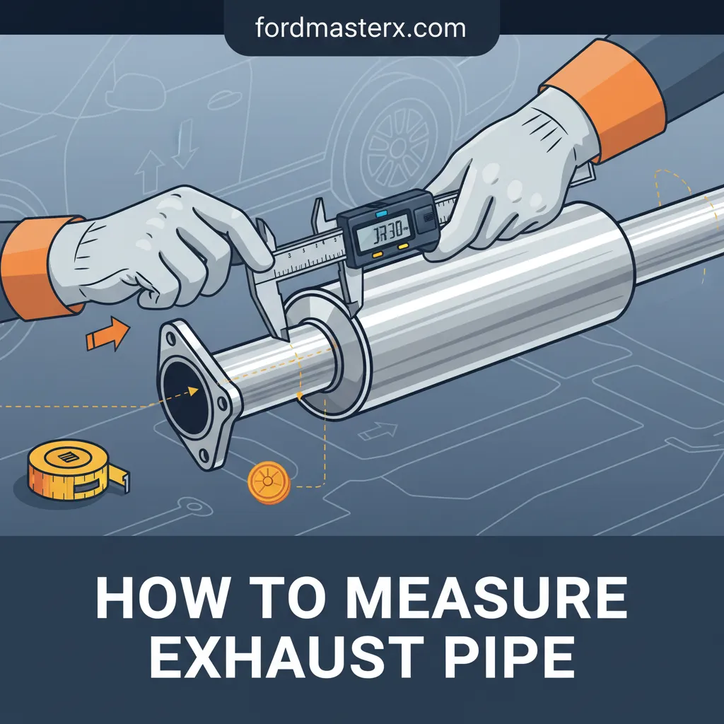
How To Measure Exhaust Pipe For Precise Automotive Fitment
In the world of automotive engineering, a fraction of an inch is the difference between a high-performance exhaust note and a frustrating, power-robbing leak. Many DIY enthusiasts and even novice fabricators struggle with inconsistent measurements because they fail to account for wall thickness, pipe deformation, or industry-standard sizing conventions. Precision is not merely a preference; it is a requirement when dealing with thermal expansion and high-pressure gas velocity. This comprehensive guide will teach you how to master professional measurement techniques, from utilizing precision calipers to calculating centerline radii, ensuring every component you order fits perfectly the first time.
Section 1: Essential Tools to Master Exhaust Pipe Measurement Techniques
📤 Share Image
Before you even slide under a chassis, you must discover that your choice of instrumentation dictates the quality of your results. Standard tape measures are sufficient for rough-cut lengths, but they are woefully inadequate for capturing the outside diameter (OD) or wall thickness of a performance exhaust system. To learn the trade properly, you must start with a high-quality digital vernier caliper. While a budget analog unit might suffice for basic tasks, a professional-grade Mitutoyo or similar digital unit offers accuracy within +/- 0.001 inches—a level of precision essential for high-tolerance V-band or slip-fit fabrication.
In the real world, you rarely have the luxury of a bare pipe on a workbench. You will often encounter restricted spaces where a caliper’s jaws simply cannot reach. In these scenarios, a flexible tailor’s tape or even a simple piece of string becomes your primary tool. By wrapping the string around the pipe to find the circumference, you can calculate the diameter with surprising accuracy. For commercial-grade or large-bore diesel systems (4 to 6 inches), professional fabricators often employ a pi tape, which is calibrated to provide a direct diameter reading from a circumference wrap, eliminating manual calculation errors.
Environmental factors also play a role. Surface scale, rust, and carbon buildup can easily add 0.02 or 0.03 inches to your reading. Consider a scenario where a 0.05-inch discrepancy—roughly the thickness of a dime—results in an exhaust clamp that bottomed out before it could fully seal the joint. Always use a wire brush or abrasive pad to clean the measurement site down to the bare metal. This ensures the caliper jaws seat flush against the actual tubing wall rather than debris.

Section 2: Understand the Difference Between Outside Diameter and Inside Diameter
To explore the nuances of exhaust sizing, one must first accept a hard industry truth: exhaust tubing is sold by the Outside Diameter (OD). This differs from standard plumbing pipe, which is categorized by Nominal Pipe Size (NPS) and often relates to the internal bore. In the automotive world, when you buy a “2.5-inch pipe,” the 2.5 inches refers specifically to the distance across the outer edges of the tube. However, the performance characteristics and fitment logic often depend on the Inside Diameter (ID) and the wall thickness (referred to as gauge).
The relationship between OD and ID is dictated by the gauge of the steel. In performance applications, 16-gauge and 18-gauge are the most common standards. A 16-gauge wall is approximately 0.065 inches thick. To calculate the internal flow area, you must subtract twice the wall thickness from the OD. For a 2.5-inch 16-gauge pipe, the math is: 2.5″ – (0.065″ x 2) = 2.37″ ID. If you inadvertently switch to 14-gauge (0.083″) for a repair, your ID drops to 2.334″, creating a stepped restriction in the exhaust flow that can disrupt scavenging and introduce turbulence.
By The Numbers: Gauge vs. Wall Thickness
16-Gauge (Standard)
18-Gauge (Lightweight)
14-Gauge (Heavy Duty)
Furthermore, you must account for ovalization. During the bending process—especially with lower-quality “crush” bends—the pipe will slightly deform, losing its perfect circularity. This makes a single-point measurement unreliable. Professional fabricators take measurements across multiple axes (vertical, horizontal, and 45-degree) and average them to discover the true effective diameter. This is particularly essential when matching a new muffler to an existing tailpipe; if the tailpipe is ovalized, a standard slip-fit will not seat properly without reshaping the metal.

Section 3: Step-by-Step Guide to Measuring Straight Pipe Sections
Consistency is the hallmark of a professional. When measuring a mid-pipe or straight section, follow this repeatable process to ensure your data is accurate enough for custom ordering or fabrication. This beginner-friendly sequence will prevent the most common errors seen in the field.
📋
Step-by-Step Measurement Protocol
Use a wire brush to remove rust, road grime, or loose scale. If you are measuring at a cut end, ensure there is no internal or external burr that could offset the caliper jaws.
Place the caliper jaws around the pipe. They must be perfectly perpendicular to the run of the pipe. If the caliper is tilted diagonally, the reading will be artificially larger than the actual OD.
If frame rails obstruct the caliper, wrap a non-elastic string around the pipe. Mark the overlap point precisely with a fine-tip pen, then measure the flat length of that string against a ruler.
Divide your circumference by Pi (3.14159). For example, a 7.85-inch circumference indicates a 2.5-inch OD pipe. Verify this against standard 0.25-inch aftermarket increments.
Always verify your calculated results against standard automotive increments. While exotic European manufacturers sometimes use metric sizing (e.g., 60mm or 70mm), the vast majority of the automotive aftermarket scales in 0.25-inch increments (2.0″, 2.25″, 2.5″, 3.0″). Heavy-duty truck systems typically scale in 0.5-inch increments. If your math results in a 2.42-inch diameter, it is highly likely you are looking at a 2.5-inch pipe that has been slightly compressed or is heavily coated.
Section 4: How to Measure Exhaust Bends and Centerline Radius
Fabricating a custom tailpipe or a turbocharger downpipe requires more than just knowing the OD; you must master the concept of the Centerline Radius (CLR). The CLR is the distance from the center of the bend’s curvature to the center of the pipe itself. This is the gold-standard metric for mandrel-bent components because it determines how tight the turn is and whether it will clear chassis components like leaf springs or fuel tanks.
Most high-quality “tight radius” mandrel bends follow a 1.5D rule. This means the CLR is 1.5 times the OD. For a 3-inch pipe, a standard mandrel bend will have a 4.5-inch CLR. Knowing this allows you to pre-visualize clearance before ordering parts.
To measure an existing bend, start by identifying the degree of the bend using a magnetic protractor or a digital angle finder. Common angles are 45, 60, and 90 degrees. Next, measure the “leg length”—the straight section of tubing that extends from the end of the curve before it reaches a flange or another bend. When ordering material, you must calculate the “developed length,” which is the total amount of straight pipe required to create that bend plus the legs. The formula for the arc length of the bend is: (2 x Pi x CLR) x (Angle / 360).
✅ Mandrel Bend
- Consistent ID throughout the bend
- Smooth internal surface for airflow
- Easier to measure and calculate CLR
- Required for performance applications
❌ Crush Bend
- Restricted ID at the apex of the turn
- Turbulent airflow and high backpressure
- Distorted OD makes measurement difficult
- Found mostly on cheap budget exhausts
Section 5: Measuring for Slip-Fit and Flange Connections
The most frequent point of failure in an exhaust system is the junction between two components. To understand how to secure these joints, you must measure for two primary connection types: slip-fits and flanges. In a slip-fit (or “swage”) joint, one pipe is expanded to allow another pipe of the same OD to slide inside it. You must measure the depth of this expansion. For a secure, leak-free seal that accounts for thermal expansion and vibration, a minimum overlap of 2 inches is standard for 2.5-inch and 3-inch systems.
When dealing with flange connections, the most critical measurement is the Bolt Circle Diameter (BCD). This is not the distance between adjacent holes, but the diameter of the circle that passes through the centers of all the bolt holes. To measure this on a 2-bolt flange, use your caliper to measure from the outside edge of one hole to the inside edge of the opposite hole—this compensates for the hole diameter and gives you the true center-to-center distance.
V-Band Flanges
Measured by the “apex” or outer flange diameter rather than pipe OD. Ensure the clamp matches the flange profile (male/female or flat).
Ball and Socket
Measure the maximum diameter of the “ball” flare to ensure it seats fully within the socket of the mating flange.
For existing components like mufflers or resonators where you cannot see the internal structure, use a telescoping gauge (also known as a snap gauge). Insert the gauge into the inlet, lock it, and then measure the gauge with your digital calipers. This provides the exact ID of the muffler inlet, which is often slightly oversized by the manufacturer to accommodate a slip-fit over the intermediate pipe. Accounting for these tolerances is the secret to a professional installation that doesn’t require “hammering” parts together.
Steel expands when heated. A 3-foot section of stainless steel exhaust can grow by as much as 1/8 of an inch at operating temperature. If your measurements and fitments are too tight against the chassis or heat shields when cold, they will rattle or bind once the system reaches temperature.
In summary, achieving professional automotive fitment requires a disciplined approach to measurement. Always prioritize the Outside Diameter (OD) as your primary metric for ordering tubing, but keep wall gauge and Centerline Radius at the forefront of your fabrication strategy. Use digital calipers for accessible sections and the circumference-to-diameter conversion for tight-clearance areas. By accounting for surface debris, thermal expansion, and flange bolt patterns with sub-millimeter precision, you eliminate the guesswork that leads to leaks and performance loss. Now that you understand how to measure your system with professional accuracy, audit your exhaust dimensions and select the high-quality mandrel-bent components required for your next upgrade.
Frequently Asked Questions
Are exhaust pipes measured by ID or OD?
In the automotive industry, exhaust pipes are almost exclusively measured and sold by their Outside Diameter (OD). This differs from residential plumbing (PVC) or structural pipe, which is often measured by Nominal Pipe Size (NPS) or Inside Diameter (ID). When purchasing a 3-inch exhaust pipe, the exterior will measure exactly 3 inches, while the interior will vary based on the wall thickness.
What is the most common wall thickness for exhaust pipes?
The most common wall thickness for automotive exhaust is 16-gauge, which is approximately 0.065 inches thick. Performance applications or weight-sensitive builds may use 18-gauge (0.049 inches), while heavy-duty or industrial systems might utilize 14-gauge (0.083 inches). Knowing the gauge is essential for determining the internal flow area and selecting the correct welding settings.
How do I measure an exhaust pipe that is still on the car?
If you cannot reach the end of the pipe with calipers, use the circumference method. Wrap a flexible tape measure or a piece of string around the pipe to find the total distance around. Divide this number by 3.14159 (Pi) to find the Outside Diameter. For example, a circumference of approximately 7.85 inches indicates a standard 2.5-inch OD pipe.
How do I measure the flange bolt pattern?
To measure a 2-bolt or 3-bolt flange, you need the Bolt Circle Diameter (BCD). For a 2-bolt flange, measure from the center of one hole to the center of the opposite hole. For a 3-bolt flange, measure from the center of one hole to the center of the pipe, then multiply by two, or use a specific BCD formula to ensure the new gasket or mating flange aligns.
What is the difference between a mandrel bend and a crush bend in measurement?
A mandrel bend maintains a consistent diameter throughout the curve using an internal support tool during manufacturing. A crush bend (common in budget shops) allows the pipe to wrinkle and collapse slightly, reducing the cross-sectional area. When measuring a crush bend, you must measure the narrowest part of the ‘crush’ to understand the actual flow restriction of the pipe.