Fuel Pump Ford F150 Fuel System Diagram: Diagnosis Guide
A fuel pump Ford F150 fuel system diagram illustrates the flow from the gas tank through the lines to the injectors. It highlights the pump, filter, and electrical connections to the ECU. Using this map helps you troubleshoot low pressure, failed starts, or a check engine light related to fuel delivery.
📌 Key Takeaways
- Visualizes the path of fuel from the tank to the engine rail
- Identifies the fuel pump driver module and relay locations
- Essential for locating fuel line disconnect points safely
- Shows electrical integration between the pump and the ECU
- Best used when diagnosing sputtering or no-start conditions
Finding yourself stranded with a Ford F-150 that cranks but won’t start is a frustrating experience that often points toward a failure in the delivery of gasoline. To diagnose and repair this essential system effectively, you need a high-quality fuel pump ford f150 fuel system diagram to guide your troubleshooting. This diagram serves as a roadmap, illustrating the path from the fuel tank to the combustion chamber, including the electrical signals sent by the computer and the physical movement of pressurized liquid. Understanding this schematic is the first step in determining whether you are dealing with a simple blown fuse, a faulty driver module, or a complete pump failure. In this guide, you will learn how to interpret these technical layouts, identify every key component in the fuel assembly, and follow a systematic approach to restoring your truck’s performance.
Comprehensive Analysis of the F-150 Fuel System Diagram
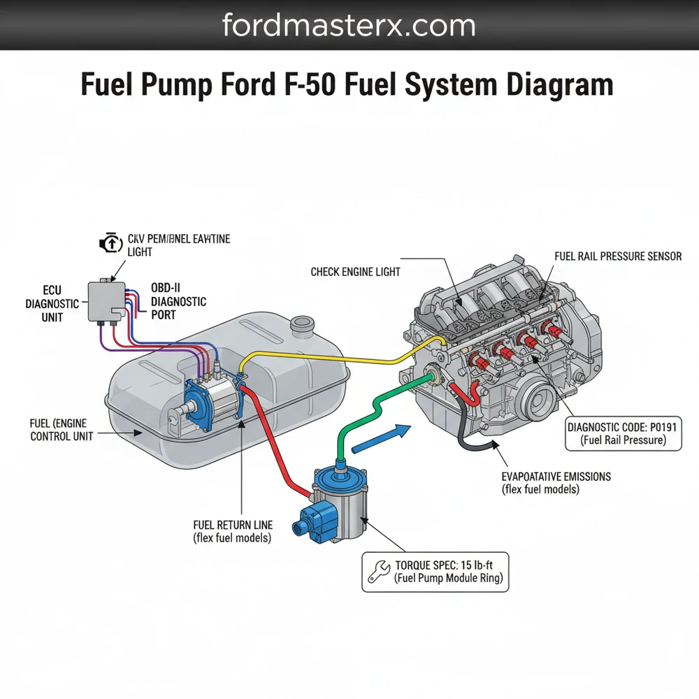
A fuel pump ford f150 fuel system diagram is more than just a picture of a tank; it is a complex map of electrical and mechanical interactions. Modern F-150 trucks typically utilize a “returnless” fuel system, which differs significantly from older designs. In a returnless system, the pump regulates pressure internally or via a specialized module, rather than sending excess fuel back to the tank through a secondary line.
The diagram begins at the Fuel Tank, which houses the Fuel Pump Assembly. This assembly is a modular unit containing the pump motor, a pre-filter (or “sock”), and the fuel level sending unit. When you turn the key, the ECU (Electronic Control Unit) sends a signal to the Fuel Pump Driver Module (FPDM). On the diagram, this is usually represented as a mid-point between the battery/fuse box and the tank. The FPDM is a frequent point of failure in these trucks, often due to corrosion on its mounting bracket.
Moving forward from the tank, the diagram illustrates the high-pressure fuel lines. These lines lead to the fuel rail, where the fuel injectors are mounted. You will also notice the Fuel Pressure Sensor, which provides real-time data to the ECU to adjust the pump speed. This feedback loop ensures that the engine receives the exact volume of fuel needed for current driving conditions. Visualizing these connections helps you identify which connectors to test with a multimeter and which lines to check for leaks.
[ ENGINE COMPARTMENT ]          [ CHASSIS / FRAME ]          [ REAR OF TRUCK ]
         |                               |                           |
   Fuel Injectors <---------- Fuel Rail <----------- Fuel Lines <----------+
         |                        |              (High Pressure)           |
         |               Fuel Pressure Sensor                              |
         |                        |                                 [ FUEL TANK ]
   [   ECU   ] <---------- [ DRIVER MODULE ] <-------------------- [ FUEL PUMP ]
         |                 (FPDM / Module)                          (Assembly)
         |                        |                                        |
   OBD-II Port <----------- [ RELAY/FUSE ] <----------------------- [ BATTERY ]
On most Ford F-150 models, the Fuel Pump Driver Module is located on the frame cross-member above the spare tire. If your diagram shows a loss of power at the pump but the fuse is good, this module is the most likely culprit.
Step-by-Step Guide to Reading and Using the Diagram
Interpreting a fuel pump ford f150 fuel system diagram requires a methodical approach. Whether you are replacing a faulty unit or simply trying to understand why your truck is stuttering, follow these steps to use the diagram for a successful repair.
1. Identify the Electrical Path
Start at the power source on your diagram. Locate the battery, then follow the line to the Central Junction Box (the fuse box). Look for the specific fuse and relay labeled for the fuel pump. Using your diagram, identify the wire colors leading from the relay to the Fuel Pump Driver Module. This allows you to use a probe to check for voltage at specific points without stripping the entire wire harness.
2. Check for Diagnostic Codes
Before turning a wrench, connect a scanner to the OBD-II port. Your diagram shows the ECU as the "brain" of the system. If the ECU detects a discrepancy in fuel pressure or an open circuit in the pump, it will trigger a check engine light and store a diagnostic code (such as P0191 or P0627). Knowing the code helps you narrow down which section of the diagram to focus on.
3. Relieve System Pressure
Safety is paramount when working with pressurized fuel. Locate the fuel pump relay or fuse on your diagram and remove it while the engine is running. The engine will stumble and die as it consumes the remaining fuel in the lines. This ensures that when you disconnect the lines at the tank or rail, you aren't sprayed with high-pressure gasoline.
4. Locate the Fuel Pump Driver Module
Using the diagram, find the physical location of the FPDM. In many F-150s, this is exposed to the elements. Inspect the housing for cracks or oxidation. If the diagram indicates power is reaching the module but not leaving it, the module has failed and must be replaced.
5. Access and Disconnect the Pump
Once the electrical system is cleared, move to the mechanical side of the diagram. You have two choices: drop the fuel tank or remove the truck bed. Most DIYers find that unbolting the bed and sliding it back provides much easier access to the top of the tank. Follow the diagram's layout to disconnect the electrical harness and the quick-connect fuel lines.
6. Remove the Lock Ring and Unit
The diagram will show a retaining lock ring holding the pump assembly in place. Use a brass drift or a specialized fuel tank lock ring tool to rotate the ring counter-clockwise. Lift the assembly out carefully, noting the orientation of the float arm so you don't damage the new unit during installation.
7. Final Inspection and Reassembly
While the fuel system is open, it is a great time to perform a broader engine health check. Inspect the accessory belt for wear and check the timing chain area for any unusual noise if the engine is running. Ensure your coolant flow is optimal to prevent engine heat from affecting fuel rail temperatures. Reassemble the pump following the diagram in reverse order, ensuring the gasket is seated perfectly to prevent evaporative leak codes.
Always work in a well-ventilated area and keep a fire extinguisher nearby. Fuel vapors are heavier than air and can settle in low spots, creating an explosion hazard. Never use a light that isn't explosion-proof near an open fuel tank.
Common Issues and Troubleshooting with the Diagram

The fuel pump ford f150 fuel system diagram is your best friend when troubleshooting common Ford-specific issues. One of the most frequent problems is a "crank-no-start" condition caused by a corroded FPDM. By looking at the wiring on the diagram, you can bypass the module temporarily (for testing only) to see if the pump primes.
Another common issue is a clogged fuel filter. In older models, the diagram will show an external filter along the frame rail. In newer models, the filter is "lifetime" and located inside the tank as part of the pump assembly. If your truck stutters under load, use the diagram to find the fuel pressure test port (Schrader valve) on the fuel rail. Attach a gauge; if the pressure is below the specified PSI, your pump is likely nearing the end of its life.
The ECU and the check engine light also play a role. If you see a diagnostic code related to a "lean condition," the diagram helps you trace the vacuum lines or the fuel pressure regulator that might be causing the pump to underperform.
- ✓ P0171/P0174: System Too Lean - Check fuel pressure and injectors.
- ✓ P0627: Fuel Pump Control Circuit - Check the FPDM and wiring harness.
- ✓ P0087: Fuel Rail Pressure Too Low - Likely a failing pump or blocked line.
Tips and Best Practices for Fuel System Maintenance
Maintaining the components found in your fuel pump ford f150 fuel system diagram can save you thousands of dollars in repairs. The fuel pump is cooled and lubricated by the gasoline itself. If you habitually run your tank down to "empty," the pump is exposed to air and can overheat, leading to premature failure.
When installing a new pump, always clean the top of the fuel tank before removing the old unit. Debris falling into the tank is a leading cause of immediate failure for new pumps.
When replacing components, always adhere to the correct torque spec for fuel rail bolts and tank strap bolts. Over-tightening can lead to cracked housings or stripped threads, which are nightmare scenarios in a high-pressure system. Furthermore, always use high-quality, OEM-spec fuel pumps. While "budget" pumps are available, the labor involved in replacing a pump in an F-150 is significant enough that you only want to do the job once.
Finally, consider the holistic health of your vehicle. While focusing on the fuel system, ensure your accessory belt is in good condition to keep the alternator charging the battery properly. A weak battery can cause low voltage to the fuel pump, leading to poor performance that mimics a failing pump. By following the fuel pump ford f150 fuel system diagram and maintaining these best practices, you ensure your truck remains reliable for hundreds of thousands of miles.
Frequently Asked Questions
Where is the fuel pump located?
On a Ford F150, the fuel pump is located inside the fuel tank. To access it, you must either safely drop the fuel tank from the chassis or, in some cases, remove the truck bed bolts to lift the bed and reach the top of the tank assembly.
What does this fuel system diagram show?
The diagram provides a visual map of the entire fuel delivery circuit. It includes the fuel tank, the internal pump, the fuel filter, supply and return lines, the fuel rail, and the electrical wiring connecting the pump to the fuel pump driver module and the engine's ECU.
How many electrical connections does the fuel pump have?
Most Ford F150 fuel pump assemblies use a multi-pin connector. Usually, this includes two heavy-gauge wires for the pump's power and ground, along with two or three smaller wires for the fuel level sending unit, which communicates the gas level to the instrument cluster and the ECU.
What are the symptoms of a bad fuel pump?
Common symptoms include the engine cranking but not starting, sputtering at high speeds, or a loss of power under load. You may also see a check engine light on the dashboard or find a specific diagnostic code like P0191 related to fuel rail pressure sensor performance.
Can I replace the F150 fuel pump myself?
Yes, an intermediate DIYer can replace the pump, but it requires a floor jack, fuel line disconnect tools, and safety gear. Because the tank is heavy and contains flammable vapors, it is a labor-intensive job that must be performed in a well-ventilated area with very little fuel in the tank.
What tools do I need for fuel system repairs?
You will need a basic socket set, fuel line disconnect tools, and a torque wrench to meet the specific torque spec for tank strap bolts. Additionally, an OBD-II scanner is vital for reading a diagnostic code or monitoring real-time fuel pressure data during the troubleshooting process.


