Ford Upfitter Switches Wiring Diagram: Easy Setup Guide
The 2022 Ford upfitter switches wiring diagram identifies color-coded blunt-cut wires found in the engine bay or passenger kick panel. To install an accessory, connect its power lead to the designated hot wire for your chosen switch and secure the ground wire to the vehicle chassis for a complete circuit.
📌 Key Takeaways
- Identifies specific wire colors for all six auxiliary switches
- Each hot wire is protected by a dedicated fuse and relay
- A secure ground wire is essential for accessory stability
- Prevents the need for splicing into the main vehicle harness
- Use this diagram when installing light bars, winches, or radios
Installing aftermarket accessories like light bars, winches, or air compressors on a heavy-duty truck requires a clean and reliable power source. For owners of the 2022 Ford Super Duty or F-150, the factory-installed upfitter switches provide the ultimate solution for professional-grade integration. Accessing the 2022 ford upfitter switches wiring diagram is the first step toward ensuring your modifications are safe and functional. This comprehensive guide provides a detailed breakdown of the wire colors, amperage ratings, and connection points necessary for a successful installation. You will learn how to identify the correct circuits, handle pass-through wires, and maintain the electrical integrity of your vehicle’s high-voltage systems while utilizing the factory switch bank.
Understanding the 2022 Ford Upfitter Switches Wiring Diagram Components
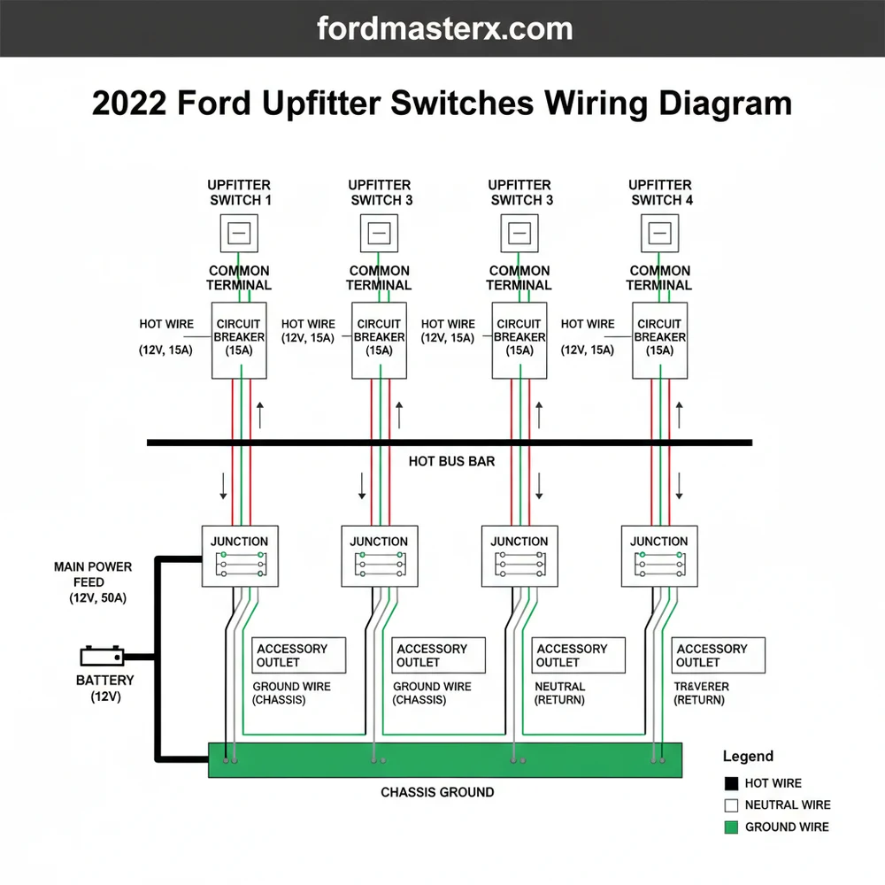
The 2022 ford upfitter switches wiring diagram is centered around a dedicated power distribution box located within the engine compartment, usually positioned near the driver-side firewall or the primary battery. Unlike standard household wiring that utilizes a neutral wire and a hot wire in an AC circuit, the Ford upfitter system operates on a 12-volt DC system where the chassis acts as the primary return path. The system consists of six switches, labeled Aux 1 through Aux 6, located on the overhead console. Each switch is mapped to a specific “blunt-cut” wire found in the engine bay.
Each circuit is designed with a specific amperage capacity, which determines the gauge of the wire used for that particular switch. For example, switches 1 through 4 are typically rated for 25 amps, while switches 5 and 6 are high-capacity circuits rated for 40 amps. When looking at the diagram, you will notice that the wire colors are distinct for each switch to prevent cross-wiring. A common terminal interface isn’t used here in the traditional sense; instead, Ford provides “pass-through” wires that bridge the gap between the interior cabin and the engine bay. This eliminates the need for you to drill through the firewall, preserving the vehicle’s weather seal.
Aux 1: Brown/Green (25A)
Aux 2: Violet/Orange (25A)
Aux 3: Blue/Green (25A)
Aux 4: Gray/Brown (25A)
Aux 5: Brown/White (40A)
Aux 6: Green/Orange (40A)
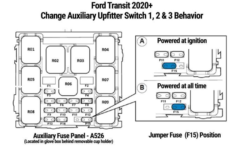
The diagram also illustrates the relationship between the switches and the ignition. Switches 1-4 are usually “hot” only when the ignition is in the run position, whereas switches 5 and 6 can be configured via a jumper in the fuse box to provide constant power even when the vehicle is off. Understanding these nuances is critical for accessories like dash cams or security lighting that might require power while the truck is parked.
[DIAGRAM_PLACEHOLDER: A detailed technical illustration showing the 6-switch overhead console connected to the engine bay power distribution box. The diagram highlights the six colored blunt-cut wires (Brown/Green, Violet/Orange, Blue/Green, Gray/Brown, Brown/White, Green/Orange) and their corresponding pass-through wires. Labels indicate the 25A and 40A fuses, the 12V hot wire connections, and the ground wire points on the vehicle chassis.]
Step-by-Step Installation Guide
Reading a 2022 ford upfitter switches wiring diagram is one thing, but physical implementation requires a systematic approach to ensure you don’t damage the vehicle’s sensitive electronics. Follow these steps to connect your accessories properly.
- ✓ Step 1: Locate the Blunt-Cut Wires. Open the hood and look for a bundle of taped wires near the driver-side fender or firewall. These are the ends of the circuits connected to your overhead switches.
- ✓ Step 2: Identify the Pass-Through Wires. If your accessory is inside the cab, you will need the pass-through bundle, which consists of four extra wires that run through the firewall. These are usually blunt-cut on both the engine side and the passenger footwell side.
- ✓ Step 3: Prepare the Accessory. Identify the power (hot wire) and the negative (ground wire) on your accessory. Ensure the accessory’s current draw does not exceed the amperage rating of the switch you have selected.
- ✓ Step 4: Strip and Crimp. Use a wire stripper to remove about half an inch of insulation from the upfitter wire and your accessory wire. Use a high-quality heat-shrink butt connector to join them. This prevents moisture from corroding the connection.
- ✓ Step 5: Establish a Solid Ground. Connect the accessory’s ground wire to a factory ground stud on the chassis. Do not use a brass screw or a self-tapping screw into plastic; a true metal-to-metal contact is required for the circuit to complete.
- ✓ Step 6: Final Test. Turn the ignition to the “On” position and toggle the overhead switch. The indicator light on the switch should illuminate, and your accessory should power up.
Never attempt to power an accessory that draws more current than the circuit’s fuse rating. For example, connecting a 45-amp winch to a 25-amp Aux 1 circuit will immediately blow the fuse and could potentially heat the wire gauge beyond its safety limit.
When performing these steps, remember that the “traveler wire” concept used in multi-way home lighting doesn’t apply directly here. However, if you are adding a relay for an exceptionally high-draw item, the upfitter wire acts as the trigger. This trigger sends a signal to the relay’s common terminal to close the circuit and pull high-amperage power directly from the battery.
Common Issues & Troubleshooting
Even with a perfect 2022 ford upfitter switches wiring diagram, you may encounter obstacles during the installation process. One of the most frequent problems is the “dead switch” scenario, where the switch light turns on, but the accessory does not. This is almost always caused by a poor ground wire connection. In automotive electrical systems, the return path is just as important as the hot wire. If your accessory isn’t grounded to a clean, unpainted portion of the frame, the circuit remains open.
Another common issue involves confusing the upfitter wires with the pass-through wires. The upfitter wires provide voltage, while the pass-through wires are simply “empty” conductors intended to help you move a signal through the firewall. If you connect your accessory to a pass-through wire but fail to connect the other end of that pass-through wire to an actual upfitter circuit, no power will reach your device.
Before finalizing any crimps, use a multimeter to check for 12V voltage at the wire end when the switch is flipped. This confirms you have located the correct color-coded wire according to the diagram.
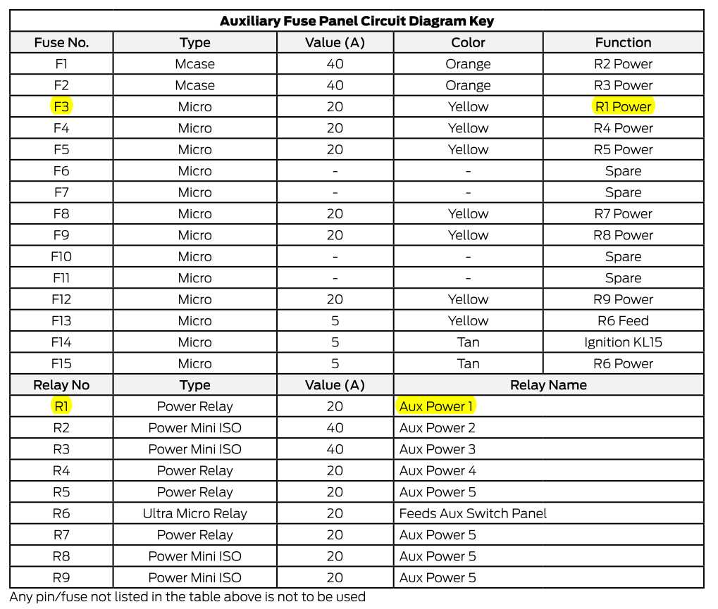
Lastly, check the fuses in the Upfitter Relay Box under the hood. If a switch was accidentally grounded during installation, the fuse will pop. Ford uses J-Case and Mini fuses for these circuits, which are easily replaceable but require the specific amperage noted in the 2022 ford upfitter switches wiring diagram.
Tips & Best Practices for Wiring Success
To achieve a factory-quality finish that lasts for the life of the truck, follow these professional best practices. First, always protect your wiring with split-loom tubing. The engine bay is a harsh environment characterized by extreme heat and vibration. Looming your wires prevents the insulation from chafing against metal edges, which could lead to a short circuit over time.
Second, pay attention to the wire gauge. While the factory provides specific gauges for the blunt-cut ends, the wire you use to extend those circuits to your accessory must match or exceed that thickness. Using a wire that is too thin for the length of the run can cause a voltage drop, leading to dim lights or underperforming equipment. For the 40-amp circuits (Aux 5 and 6), use at least 10-gauge or 8-gauge wire for long runs.
- ✓ Dielectric Grease: Apply a small amount to the connections to prevent moisture intrusion and corrosion.
- ✓ Labeling: Tag each wire near the connection point so you know exactly which switch controls which device for future maintenance.
- ✓ Avoid Wire Taps: Avoid using “vampire” or T-tap connectors. They cut into the copper strands and create weak points. Always use soldered joints or high-quality crimps.
Finally, consult your owner’s manual in conjunction with the 2022 ford upfitter switches wiring diagram to verify the specific fuse locations for your sub-model. Different trim levels (like the XL vs. the Platinum) may have slight variations in how the relay box is mounted, though the wire colors remain consistent across the 2022 lineup. By following these steps and maintaining a clean wiring environment, you ensure that your truck’s electrical system remains robust and reliable for all your off-road and work-site needs.
Frequently Asked Questions
Where is the upfitter wiring located?
The blunt-cut wires are typically located in the engine compartment, usually tucked near the firewall or the power distribution box on the driver side. Some models also include a set of pass-through wires located behind the passenger-side kick panel for easy access to the vehicle cabin.
What does this wiring diagram show?
This diagram illustrates the electrical path from the overhead switch console to the relay box and finally to the blunt-cut leads. It identifies which color-coded hot wire corresponds to each switch, ensuring you select a circuit with the appropriate amperage rating for your specific aftermarket accessory.
How many connections does the upfitter system have?
The system features six independent switches, each connected to a common terminal within the relay box. Each switch provides a single hot wire output. You must provide your own ground wire connection to the vehicle frame or a grounding bus to complete the electrical circuit for your devices.
What are the symptoms of a bad upfitter connection?
If an accessory fails to power on, check if the switch light activates. A dark switch often suggests a blown fuse in the engine bay. If the switch lights up but the device doesn’t work, the most common culprit is a loose ground wire or a disconnected hot wire.
Can I install these accessories myself?
Yes, Ford designs the upfitter system to be user-friendly for DIY enthusiasts. Since the relays and fuses are pre-installed, you only need to perform basic wire stripping and crimping. Following the 2022 Ford upfitter switches wiring diagram ensures you maintain factory safety standards during the installation.
What tools do I need for this task?
You will need a basic electrical tool kit including wire strippers, a crimping tool, and heat-shrink butt connectors. A digital multimeter is highly recommended to verify that the hot wire is receiving 12V power when the switch is toggled and to check for continuity on your ground.


