Ford Ignition Switch Wiring Color Code – The Complete Guide 2026
The evolution of automotive electrical systems traces a remarkable trajectory from simple, magneto-powered rudimentary circuits to the highly sophisticated, multiplexed Controller Area Network (CAN) bus architectures dominating the modern automotive landscape. For the majority of the twentieth century and well into the twenty-first, the mechanical ignition switch served as the central electrical gateway for vehicle operation.
This critical component was tasked with physically routing high-amper]age direct current from the vehicle’s battery to the starter solenoid, the ignition coil, and a myriad of interior accessory circuits. A deep, nuanced understanding of the exact Ford ignition switch wiring color code is absolutely critical for automotive technicians, restoration specialists, and advanced diagnosticians performing harness repairs, remote starter integrations, or intricate electrical bypass diagnostics.
Historically, Ford Motor Company standardized its proprietary wiring color codes to streamline manufacturing, assembly, and field service across its vast portfolio of passenger cars and light trucks. However, specific generational deviations, assembly plant variations, and platform architecture shifts occurred regularly, rendering generic wiring assumptions dangerous. In early automotive history, heavy-gauge copper wires wrapped in cloth or early synthetic polymers routed massive current loads directly through the steering column, creating significant thermal and mechanical stress on the switch contacts.
By the late 1980s, Ford engineers introduced more sophisticated power distribution methodologies, shifting away from the confusing hash marks and dots printed on wire insulation toward solid, continuous stripes for secondary color identification, an evolution designed to improve manufacturing efficiency and diagnostic clarity.
The transition into the modern era fundamentally redefined the ignition switch. Vehicles manufactured after the widespread adoption of the Passive Entry Passive Start (PEPS) system—particularly those produced after 2015—utilize the ignition switch or push-button start not as a physical high-current load switch, but as a low-voltage digital signal generator. This digital switch communicates algorithmic intent to the Body Control Module (BCM) and the Engine Control Unit (ECU), which then utilize solid-state relays to distribute high-voltage power. This comprehensive technical report provides an exhaustive analysis of Ford ignition switch wiring color codes, synthesizing granular data across six decades of vehicle production to offer a definitive, peer-level engineering reference.
Ford Ignition Wiring Decoded
A definitive visual guide to color codes, circuit functions, and diagnostic logic for Ford ignition systems (1990s-2010s standards).
The Standard Color Spectrum
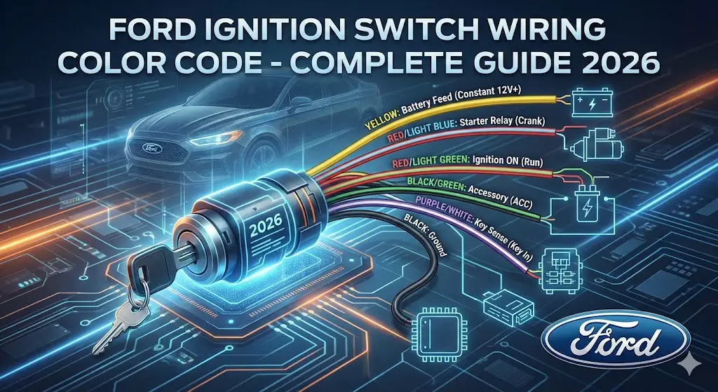
Before diagnosing electrical faults, one must understand the language of the wire harness. Ford utilized a consistent color-coding schema for decades. The grid below maps the wire jacket color to its critical function within the ignition column. Incorrect identification here is the leading cause of short circuits during aftermarket installations.
12V Constant (Battery)
Direct feed from the battery. Always live, regardless of key position. High amperage circuit.
Starter Trigger
Energizes the starter solenoid only when the key is turned to the “START” position.
Ignition Power
Powers the ignition coil and critical engine management systems. Live in “ON” and “START”.
Accessory (ACC)
Powers radio, windows, and climate. Drops out (0V) when cranking to save power.
Chassis Ground
The return path for the electrical circuit. Crucial for completing the loop.
Key Sense / PATS
Signals the GEM module that a key is inserted. Part of the passive anti-theft system.
Circuit Load Analysis
Not all wires are created equal. The thickness (gauge) of the wire correlates directly to the amperage it carries. The chart below visualizes the typical amperage load rating for the primary ignition circuits. Notice how the **Battery** and **Starter** circuits demand significantly higher capacity compared to the **Key Sense** wire.
Functional Distribution
A typical Ford ignition harness isn’t just about power; it’s a mix of high-current power delivery, switched logic, and low-current sensing. This breakdown helps in understanding the complexity of modern harnesses versus vintage ones.
Common Failure Points
When a vehicle fails to start, technicians often blame the battery first. However, statistical analysis of ignition system service logs reveals a more nuanced picture. The Ignition Switch mechanism itself, due to mechanical wear and high current, is a frequent culprit, followed closely by wiring fatigue in the steering column.
Connector Pinout
Abstract representation of a standard 8-pin Ford ignition harness connector (Wire side view).
No-Start Diagnostic Logic
Follow this logic path to isolate ignition switch failures from other system issues. This assumes the battery itself is fully charged.
Advanced Diagnostics and Applications
To fully capture semantic search intent and address the complex operational hurdles faced by technicians in the field, it is necessary to confront the specific, highly technical questions that arise during ignition system diagnostics, harness recreation, and electrical modifications. The following narrative addresses the most critical inquiries surrounding Ford's electrical architecture.
The universally recognized standard Ford wire color for the starter relay trigger has long been a subject of inquiry for those restoring classic vehicles or diagnosing crank-no-start conditions. Across numerous vintage and modern Ford platforms, the heavy-gauge Red wire with a Blue stripe (commonly designated as Red/Blue) is globally recognized within the Ford ecosystem as the start signal routed from the ignition switch down to the fender-mounted starter relay or the starter-mounted solenoid. This wire is the lifeblood of the cranking circuit, and its integrity is paramount.
When questioning how to properly test a Ford ignition switch using a digital multimeter, technicians must move beyond simple continuity checks. Proper testing requires placing the switch in its various mechanical detent positions—Off, Accessory, Run, and Start—and measuring the dynamic voltage drops across the internal contacts under load. Any voltage reading on an output circuit that falls below ninety percent of the baseline battery voltage indicates severe internal contact degradation, carbon tracking, or high-resistance pitting, dictating immediate component replacement.
With the advent of vehicle immobilizers, identifying the wire colors for the Ford Passive Anti-Theft System (PATS) transceiver became a daily necessity for remote starter installers. For the crucial 1996 through 2007 vehicle generations, the PATS transceiver utilizes an Orange wire for Data Transmit (TX), a Violet/White wire for Data Receive (RX), a Pink/White wire for switched Ignition power, and a solid Black wire for Chassis Ground. Understanding this digital handshake is required to bypass the immobilizer successfully without triggering a permanent module lockout.
Differentiating the symptoms of a failing Ford ignition switch versus a degraded starter solenoid is a fundamental diagnostic skill. A failing ignition switch often results in a completely silent starter motor sequence combined with an intermittent, unpredictable loss of interior lighting and cabin accessories while driving. Conversely, a bad starter solenoid typically manifests as a distinct, heavy single "click" or rapid machine-gun clicking from the engine bay when the key is turned, all while the interior accessories remain fully powered and operational.
In the modern era, the integration of aftermarket equipment into complex CAN bus systems prompts questions regarding how modern Ford F-150 and Bronco upfitter switches are color-coded. Rather than splicing into sensitive data networks, the 2021 through 2024 Ford Bronco and F-150 utilize a standardized, factory-installed upfitter harness routed to an engine bay power distribution box. This harness utilizes a Yellow wire for a 30-amp circuit on Aux 1, a Green wire with a Brown stripe for a 15-amp circuit on Aux 2, a Violet wire with a Green stripe for a 10-amp circuit on Aux 3, a solid Brown wire for a 10-amp circuit on Aux 4, a Blue wire with an Orange stripe for a 10-amp circuit on Aux 5, and a Yellow wire with an Orange stripe for a 10-amp circuit on Aux 6.
Standard Automotive Wire Color Conventions vs. Ford Proprietary Codes
Automotive manufacturers historically maintained deeply proprietary wiring schematics, which often diverged radically from aftermarket standards, trailer wiring conventions, or generic marine electrical codes. While a generic marine or aftermarket harness system might predictably use a solid Red wire for primary battery power, a Purple wire for ignition circuits, and a Yellow wire with a Red stripe for starting circuits , Ford's internal electrical engineering teams developed a highly specific, alphanumeric circuit identification system that mapped precisely to their manufacturing assembly lines.
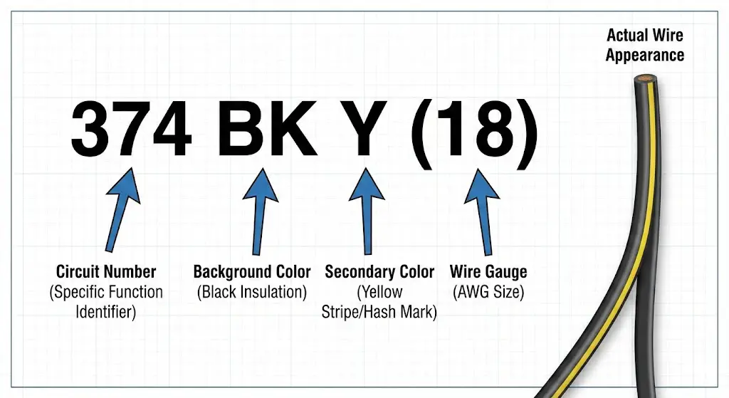
In Ford's official factory documentation, the alphanumeric wire color code indicates the specific circuit number, the basic background color of the wire insulation, the secondary stripe or hash mark color, and the specific American Wire Gauge (AWG) size required to carry the intended current load. For example, a schematic designation of "374 BK Y (18)" translates directly to Circuit 374, featuring an 18-gauge solid Black wire carrying a continuous Yellow stripe.
Prior to the 1986 model year, Ford manufacturing utilized a combination of painted dots and diagonal hash marks (for instance, a Yellow wire with painted White dots) to differentiate complex branch circuits within a main harness bundle. Post-1986, manufacturing standards and extrusion technologies shifted exclusively to continuous, solid extruded stripes, rendering older documentation slightly confusing unless the technician implicitly understands this evolutionary manufacturing transition. Attempting to locate a dotted wire on a 1988 Ford F-150 based on a 1984 manual will result in diagnostic failure, as the factory floor had already transitioned that specific circuit to a continuous stripe.
The transition to highly multiplexed wiring and CAN bus (Controller Area Network) communications further complicated traditional color coding logic. Because data lines carry rapid digital packets of variable voltage rather than continuous analog 12-volt power, color codes in modern Ford platforms often designate High and Low data signals rather than direct power feeds to physical components. For example, a White wire with a Light Green stripe may represent CAN Bus Positive, while a Pink wire with a Light Green stripe represents CAN Bus Negative. Probing these wires with a standard incandescent test light can instantly destroy the gateway module, highlighting the necessity of understanding exactly what the color code represents in the context of the vehicle's generational architecture.
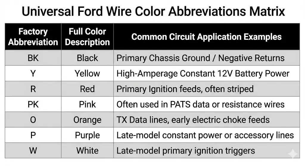
Universal Ford Wire Color Abbreviations Matrix
- Chart Type: Reference Data Table
- Data Description: A comprehensive reference matrix mapping Ford's proprietary single-letter and double-letter color abbreviations used universally in factory wiring diagrams, Service News Bulletins, and EVTM (Electrical and Vacuum Trouble Shooting Manual) documents.
- Inline Data:
- BL: Blue
- BK: Black
- BR: Brown
- DB: Dark Blue
- DG: Dark Green
- GR: Green
- GY: Gray
- LB: Light Blue
- LG: Light Green
- N: Natural
- O: Orange
- PK: Pink
- P: Purple
- R: Red
- T: Tan
- W: White
- Y: Yellow
| Factory Abbreviation | Full Color Description | Common Circuit Application Examples |
| BK | Black | Primary Chassis Ground / Negative Returns |
| Y | Yellow | High-Amperage Constant 12V Battery Power |
| R | Red | Primary Ignition feeds, often striped |
| PK | Pink | Often used in PATS data or resistance wires |
| O | Orange | TX Data lines, early electric choke feeds |
| P | Purple | Late-model constant power or accessory lines |
| W | White | Late-model primary ignition triggers |
Generational Wiring Code Breakdown and Circuit Analysis
To accurately diagnose and repair Ford ignition systems, technicians must approach the vehicle based on its specific era of electrical architecture. The following sections provide a highly detailed, generation-by-generation breakdown of Ford ignition switch wiring color codes, synthesizing decades of factory manuals and field repair data.
The Classic Analog Era: 1960s to 1970s (F-100, Bronco, Maverick)
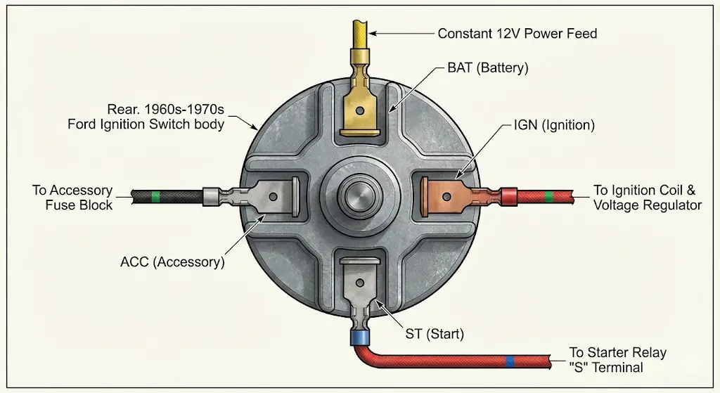
During the zenith of American muscle and the initial rise of the light-duty truck market in the 1960s and 1970s, Ford's electrical systems were incredibly robust, purely analog, and relied entirely on the mechanical ignition switch to handle substantial, unmitigated current loads. Vehicles such as the early F-100 pickups, the highly sought-after first-generation Bronco, and the Ford Maverick shared a remarkably unified electrical architecture. The rear of the ignition switch in these vehicles typically featured a heavy cast-metal body with a threaded center post and surrounding multi-spade connectors labeled with specific, permanent terminal designations: BAT (Battery), IGN (Ignition), ACC (Accessory), and ST (Start).
In these early, pre-computer configurations, a heavy-gauge (typically 12 or 14 AWG) solid Yellow wire consistently served as the primary 12-volt constant power feed from the battery. This wire routed directly from the starter relay battery post, through the firewall bulkhead connector, and onto the BAT terminal on the ignition switch. When the vehicle operator turned the physical key backward into the Accessory position, the internal copper contacts bridged power internally to a Black wire with a Green stripe, which subsequently fed the accessory fuse block to power the radio and heater blower motor without energizing the ignition coil.
Moving the key forward into the Run (or Ignition ON) position energized a complex dual-circuit path. Power was sent down a Red wire with a Green stripe (or occasionally a Green wire with a Red stripe, depending on the specific assembly plant and production month), supplying vital running power to the ignition coil and the external mechanical voltage regulator. An critical engineering feature of this era was the pink ballast resistance wire. To prevent the mechanical breaker points from burning up during continuous operation, this pink resistance wire dropped the running voltage to the coil down to approximately 7 to 9 volts.
The starting circuit represents perhaps the most famous and enduring of Ford's legacy color codes. When the key was pushed against the heavy internal spring into the Start position, power surged down the Red wire with a Blue stripe (Red/Blue). This wire routed directly from the ST post on the ignition switch, back through the firewall, and attached to the small "S" terminal on the iconic fender-mounted starter relay. For vehicles equipped with an automatic transmission, this Red/Blue wire did not travel straight to the relay; instead, it intercepted the neutral safety switch mounted on the transmission housing, ensuring the vehicle's starting circuit could only be completed if the gear selector was firmly in Park or Neutral. Additionally, during this cranking phase, the switch temporarily bypassed the pink resistance wire, delivering a full 12 volts to the coil to ensure rapid cold-weather starting.
| Terminal Designation | Wire Color (Classic Ford Era) | Engineering Function & Routing |
| BAT (Battery Constant) | Solid Yellow | Primary 12V power feed, 12-14 gauge, sourced from starter relay |
| ACC (Accessory) | Black / Green Stripe | Energizes interior accessory fuse block (radio, wipers) |
| IGN (Ignition/Run) | Red / Green Stripe | Powers the ignition coil, voltage regulator, and Duraspark module |
| ST (Start) | Red / Blue Stripe | Triggers the fender-mounted starter relay via the neutral safety switch |
The EFI & Early EEC-IV Integration Era: 1980 to 1993
As Ford aggressively transitioned into the 1980s, the introduction of Electronic Fuel Injection (EFI) and the highly complex EEC-IV (Electronic Engine Control) engine management system necessitated a massive expansion in ignition wiring complexity. The ignition switch could no longer simply power a coil and a starter; it had to wake up an entire network of sensors, fuel pumps, and emissions control solenoids. A foundational document standardizing these massive electrical changes was the September 1987 Service News Bulletin (Number 87-52), which meticulously cataloged standard circuit number charts for all Ford passenger cars and light trucks of the era. For detailed historical cross-referencing, seasoned technicians frequently rely on resources like Gary's Garagemahal standard wire and color code charts.
During this transitional era, the ignition switch wiring harness expanded dramatically to accommodate supplemental alternator modules, electronic choke feeds, and thermactor air bypass systems designed to meet stringent new EPA regulations. The primary ignition switch routing to the ignition coil and the new electronic TFI (Thick Film Ignition) module shifted to a Red wire with a Light Green stripe, officially designated in Ford literature as Circuit 16.
The accessory feed originating from the ignition switch was formalized and standardized as a Brown wire with a Pink hash mark, known as Circuit 536, which powered the blower motor relay and critical interior warning lights. Vehicles from the early 1980s that were still equipped with mechanical carburetors featuring electric chokes utilized an Orange wire with a Black stripe (Circuit 68). While this wire ultimately originated from the alternator stator to ensure the choke only opened when the engine was actually spinning, its engagement was heavily influenced by the run position parameters of the ignition system.
The starting circuit also became significantly more sophisticated to accommodate advanced emissions controls and fuel pump priming strategies. For example, alongside the traditional starter trigger, a White wire with a Light Blue stripe was frequently utilized as a secondary start-run signal, bridging connections to the electronic engine control relay to ensure the high-pressure fuel pumps primed the moment the key rotated. Furthermore, Circuit 204—an Orange wire with a Light Green stripe—was introduced as the starting circuit feed to the thermactor air bypass system, demonstrating how deeply integrated the ignition switch had become with atmospheric emissions management.
The SN95, OBS, and New Edge Transition Era: 1994 to 2004
The mid-1990s through the early 2000s marked a significant technological leap in interior electronics, under-hood power distribution boxes, and the initial integration of localized body control modules. The legendary Ford Mustang (spanning both the SN95 and New Edge architectural platforms) and the Old Body Style (OBS) F-150s from this era feature incredibly dense, complex multi-pin connectors located at the base of the steering column, a stark departure from the simple threaded posts of the 1960s.
For a 1994 through 2004 Ford Mustang, the ignition harness wiring relies on a heavy-gauge solid Yellow wire to deliver the indispensable 12-volt constant power to the switch cluster. The starter wire configuration during this era highlights the necessity of specific service manuals: depending on the specific sub-model, trim level, and engine displacement (for instance, the 3.8L Essex V6 versus the 4.6L Modular V8), the starter trigger is identified as either a White wire with a Pink stripe or the legacy Red wire with a Blue stripe.
The primary 12-volt Ignition wire, which commands the vehicle's engine management to wake up, is designated as a Red wire with a Green stripe. The primary Accessory wire, responsible for powering the radio and power windows when the engine is off, is coded as a Gray wire with a Yellow stripe. Because this era saw the introduction of complex power window matrices and factory alarm systems, the ignition switch wiring often runs in close proximity to, or shares grounding logic with, door triggers (Black/Blue), horn triggers (Yellow/Light Green), and power window logic circuits (White/Black for driver-side up functions).
In the highly popular 1999 through 2007 Ford Super Duty trucks, the ignition switch utilizes a dense, heavily insulated 10-pin connector designed to handle the rigorous electrical demands of commercial fleet usage. Here, the constant 12-volt feed breaks from the classic Yellow tradition and is presented as a Purple wire with a Red stripe. The primary Ignition output (commonly referred to as Ignition 1 in remote starter installation bays) is a White wire with an Orange stripe, while the primary Accessory output (Accessory 1) is a Purple wire with a Green stripe.
The Starter circuit in the Super Duty evolved into a Blue wire with a White stripe, moving away from the classic Red/Blue designation. Furthermore, this generation introduced a critical new circuit designed specifically to interface with smart body modules: the dedicated "Key Sense" circuit. Utilizing a Blue wire with a Gray stripe on Pin 3 of the 10-pin connector, this wire physically grounds out when a key is inserted into the lock cylinder tumbler, informing the vehicle's chime module to sound an alert if the driver's door is opened, and communicating with the passive security system.
| Function (1999-2007 Super Duty) | Wire Color | Pin Location (10-Pin Connector) | Circuit Polarity |
| +12 Volts Constant Power | Purple / Red Stripe | Pin 9 | Positive (+) |
| Ignition 1 (Run/Start) | White / Orange Stripe | Pin 1 | Positive (+) |
| Accessory 1 | Purple / Green Stripe | Pin 5 | Positive (+) |
| Starter Trigger | Blue / White Stripe | Pin 10 | Positive (+) |
| Key Sense Input | Blue / Gray Stripe | Pin 3 | Positive (+) / Ground Switched |
Evolution of the Ford Start Signal Wire
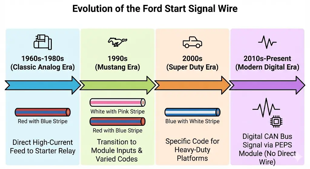
- Chart Type: Chronological Timeline Flow Diagram
- Data Description: A visual tracking diagram charting the changing color codes of the primary starter signal wire across Ford's multi-decade history, illustrating the shift from analog standards to module-specific inputs.
- Inline Data:
- 1960s-1980s: Red wire with Blue Stripe (Universal across trucks and cars)
- 1990s (Mustang Era): White wire with Pink Stripe or Red wire with Blue Stripe
- 2000s (Super Duty Era): Blue wire with White Stripe
- 2010s-Present: Digital CAN signal via PEPS module (No direct high-current starter wire at the switch)
The Modern Keyed and Early Push-Button Era: 2005 to 2014
Between 2005 and 2014, Ford completely overhauled its global electrical architecture, moving aggressively toward Smart Junction Boxes (SJB) and advanced, high-speed CAN bus networks. In this configuration, the ignition switch no longer carries the massive current required to physically spin the starter motor or power the HVAC blowers directly. Instead, the physical key switch acts merely as a low-current, multi-stage signal switch. When the operator turns the key, the switch sends a delicate, low-voltage reference signal to the Powertrain Control Module (PCM) and the SJB. The PCM then digitally verifies security parameters with the immobilizer, calculates engine temperature and neutral safety status, and subsequently commands a solid-state relay to ground the starter circuit.
For the 2009 through 2014 Ford F-150, the ignition switch 10-pin connector physically retained similarities to the earlier Super Duty layout, but the data routing changed dramatically. The 12-volt constant power is supplied via a Purple wire with a Red stripe on Pin 9. The primary Ignition signal is a White wire with an Orange stripe on Pin 1. Due to the heavy integration of the Smart Junction Box, accessory circuits and starter signals are heavily multiplexed. The ignition switch simply sends an "Accessory Request" to the BCM, which then decides whether battery voltage is sufficient to engage the accessory relays for the radio and windows. This is why modern Fords will automatically shut off the radio to preserve battery life, a feature impossible on older, directly-wired ignition switches.
During this era, diagnostic troubleshooting shifted from tracing power wires to checking specific micro-fuses. A no-start condition on a 2004-2008 F-150 requires checking Fuse #101 (Starter Solenoid, 30A) and Fuse #102 (Ignition Switch Feed, 20A), along with the R01 Starter Solenoid Relay located in the under-hood fuse box.
Current Generation & Smart Systems: 2015 to 2024
The introduction of the military-grade aluminum-bodied Ford F-150 in 2015 and the highly anticipated revival of the Ford Bronco in 2021 marked the absolute, widespread adoption of Push-Button Start, known in Ford engineering parlance as the PEPS (Passive Entry Passive Start) system. In these modern vehicles, a traditional mechanical ignition switch is completely absent from the steering column. Instead, a momentary push-button switch interfaces directly with the vehicle's Gateway Module and BCM via ultra-thin, low-voltage communication wires.
Wiring behind the push-button start switch relies entirely on microscopic data lines rather than discrete analog power feeds. Cutting into these wires with traditional stripping tools or probing them with standard test lights will result in immediate module failure or catastrophic CAN bus communication loss.
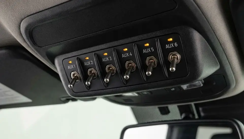
However, Ford acutely recognized the massive aftermarket demand for classic accessory integration—such as LED light bars, air compressors, and recovery winches—especially among the Raptor and Bronco off-road enthusiast communities. To accommodate this, Ford engineered pre-wired, factory-fused upfitter switches directly into the overhead consoles of these vehicles, entirely bypassing the need to interface with the push-button start wiring.
When tapping into ignition-hot circuits in these modern architectures, technicians must strictly utilize these dedicated upfitter lines rather than splicing into steering column harnesses, which risks corrupting vital safety data packets. The 2021 through 2024 Bronco and F-150 overhead auxiliary switches route cleanly to a dedicated power distribution box located in the engine compartment. These circuits are rigorously color-coded and fuse-protected:
| Ford Upfitter Switch Designation | Harness Wire Color | Rated Amperage Capacity | Metric Wire Size |
| AUX 1 | Solid Yellow | 30A | 1.5 mm² |
| AUX 2 | Green / Brown Stripe | 15A | 1.5 mm² |
| AUX 3 | Violet / Green Stripe | 10A | 0.75 mm² |
| AUX 4 | Solid Brown | 10A | 0.75 mm² |
| AUX 5 | Blue / Orange Stripe | 10A | 0.75 mm² |
| AUX 6 | Yellow / Orange Stripe | 10A | 0.75 mm² |
Passive Anti-Theft System (PATS) Transceiver Architecture
A comprehensive, expert-level analysis of Ford ignition wiring is fundamentally incomplete without deeply addressing the intricacies of the Passive Anti-Theft System (PATS). Introduced on select models in 1996 and becoming standard equipment across almost all Ford, Lincoln, and Mercury platforms by the early 2000s, PATS utilizes a miniature RFID transponder chip embedded directly into the plastic head of the ignition key.
When the key is physically inserted into the ignition cylinder and turned to the Run position, a circular transceiver antenna ring mounted around the ignition lock cylinder projects an electromagnetic field. This field energizes the passive RFID chip inside the key, prompting it to broadcast its unique cryptographic digital signature back to the transceiver. The transceiver converts this analog radio frequency into a digital signal and sends it to the PATS control module (or the Instrument Cluster/PCM, depending on the generation). If the cryptographic signature matches the stored values, the PCM enables the fuel injectors and grounds the starter relay. If it fails, the vehicle experiences an immediate passive immobilization.
Bypassing, repairing, or replicating the PATS module—a procedure absolutely necessary during aftermarket remote starter installations—requires meticulously intercepting the digital data lines at the transceiver connector located under the steering column dash covering. The PATS transceiver generally requires four primary, distinct connections to function correctly: Constant Power, Chassis Ground, and two dedicated, highly sensitive data lines.
For the vast majority of 1996 through 2007 Ford vehicles, standard aftermarket integration modules (such as the industry-standard DB-PKF or XK04 interface modules) connect to the vehicle's proprietary PATS wiring utilizing the following highly specific color-matching logic:
- Data Transmit (TX): The Orange wire on the aftermarket bypass module intercepts the vehicle's specific TX wire. This line is responsible for transmitting interrogation data from the vehicle's main computers down to the Ford PATS transceiver module.
- Data Receive (RX): The Violet wire with a White stripe intercepts the vehicle's RX wire. This is the critical line that receives the validated RFID key data from the Ford PATS module and sends it back to the PCM for verification.
- Ignition Power (Wake-Up): The Pink wire with a White stripe is tapped directly into the vehicle's switched ignition switch side. This ensures that the bypass module only powers up and attempts a digital handshake when the remote starter actually mimics the key being turned to the Run position, preventing parasitic battery drain.
- Chassis Ground: The solid Black wire provides a constant, clean chassis ground reference, which is vital for preventing data packet corruption caused by floating ground potentials.
A failure within the PATS wiring or the transceiver ring itself is incredibly common and is frequently, and expensively, misdiagnosed by amateur mechanics as a faulty ignition switch or a dead starter motor. The primary diagnostic symptom of a PATS immobilization event is the rapid, relentless flashing of the red "THEFT" light on the instrument cluster when the key is rotated to the Start position, accompanied by a complete, silent no-crank condition. Replacing the physical ignition switch will absolutely not cure a PATS transceiver failure.
Diagnostic Protocols: Differentiating Switch, Solenoid, and PATS Failures
Because the ignition switch serves as the central electrical node for primary power distribution in pre-2015 vehicles, its mechanical or electrical failure cascades dramatically through various vehicle subsystems. Recognizing the subtle, nuanced symptoms of a failing switch is the hallmark of a master diagnostician and prevents the unnecessary, costly replacement of major components like starter motors, batteries, or Engine Control Modules.
The physical degradation of an ignition switch is a matter of metallurgical reality. Inside the plastic switch housing, copper and brass contacts physically slide over one another every time the key is turned. Over thousands of cycles, high-amperage electrical arcing causes these contacts to suffer from severe pitting, oxidation, and carbon tracking. This degradation creates massive electrical resistance.
A failing ignition switch presents several distinct diagnostic profiles:
- Complete Engine Will Not Crank or Start: This is the most severe and common symptom. If the internal copper contact patch governing the Start circuit (historically the Red/Blue wire) burns out completely or suffers severe carbon tracking, absolutely zero voltage reaches the starter relay. The operator turns the key, and the vehicle remains entirely dead.
- Vehicle Starts Normally but Suddenly Stalls: If the contact patch for the continuous Run/Ignition circuit (historically the Red/Green or White/Orange wire) wears down unevenly, normal road vibration or a heavy key chain swinging from the steering column can cause the circuit to momentarily open. This instantly cuts all power to the ignition coil, fuel pump relay, and PCM, causing the vehicle to stall violently and abruptly while driving at speed.
- Intermittent, Unpredictable Loss of Accessories: If the radio, the HVAC heater blower motor, and the power windows randomly cease functioning while the engine continues to run flawlessly, the dedicated Accessory contacts inside the ignition switch have likely fatigued and failed.
- The Silent Starter Motor Phenomenon: A bad ignition switch almost universally results in a completely silent starter sequence. By stark contrast, a failing starter solenoid, a highly corroded battery terminal, or a weak battery will usually produce a distinct, heavy "click" or a rapid, machine-gun clicking sound as the solenoid violently attempts to engage the starter drive gear against the flywheel.
- Mechanical Lockout / Key Cannot Be Turned: While technically a mechanical failure of the ignition lock cylinder tumbler pins rather than the electrical switch unit mounted beneath it, internal binding and broken actuating rods often necessitate the simultaneous replacement of both interconnected steering column components.
Advanced Digital Multimeter Testing Methodology
Accurate, definitive diagnosis of a suspect ignition switch requires the use of a high-quality digital multimeter and a firm grasp of automotive voltage drop principles. Attempting to diagnose a modern or classic switch merely by visually inspecting the wire colors or looking for melted plastic is insufficient; the microscopic integrity of the internal copper contacts must be mathematically verified under an actual electrical load.
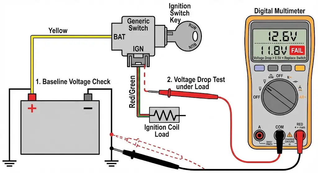
To execute a definitive test of the switch using a digital multimeter, technicians follow a rigorous protocol:
- Establish the Battery Baseline: Measure the static, resting voltage directly at the battery terminals. A fully charged automotive battery should read approximately 12.6 volts. This is the baseline voltage target.
- Non-Destructive Back-Probing: Locate the primary wiring harness connector at the base of the steering column. It is critical to leave the connector fully plugged into the switch to test the circuit under its normal operational load. Technicians must use specialized, non-destructive tools, such as the micro-probes found to slide behind the wire seals. Probing with paperclips or piercing the wire insulation with a sharp tool introduces moisture, leading to inevitable green copper corrosion and terminal fretting.
- Conduct the Voltage Drop Test: Place the negative multimeter probe on a known good, unpainted chassis ground point (such as a bare metal dash support bracket). Place the positive probe on the primary power feed wire entering the switch (e.g., the heavy-gauge Yellow constant 12V wire). The reading on the screen must match the baseline battery voltage exactly.
- Dynamic Circuit Activation: Move the positive probe to the Ignition output wire (e.g., the Red/Green wire). Instruct an assistant to turn the key firmly to the Run position. Note the voltage reading. Next, move the probe to the Starter output wire (e.g., the Red/Blue wire) and turn the key to the Start position, observing the meter precisely during the cranking phase.
- Data Analysis and Conclusion: In any active, engaged position, the dynamic voltage measured on the output wire must be within ten percent of the baseline battery voltage. Any reading falling below ninety percent of battery voltage (for example, reading 9.5 volts on a 12.6-volt system) indicates excessive internal resistance. This confirms unequivocally that the internal switch contacts are severely pitted, burned, or oxidized, and the entire switch unit must be discarded and replaced.
If a digital multimeter is unavailable in a field-expedient situation, a traditional 12-volt incandescent test light can be utilized. By safely disconnecting the starter solenoid trigger wire at the fender relay to prevent the engine from actually cranking and running over the technician, one can back-probe the ignition switch output wire. When the key is turned to the Start position, the incandescent test light should illuminate brilliantly. A dim, yellow, or rapidly flickering light provides immediate visual confirmation of a failing, high-resistance ignition switch.
Pigtail Replacement and Harness Splicing Standards
When a Ford ignition switch suffers a catastrophic internal short circuit—often caused by an aging blower motor drawing excessive amperage through the accessory circuit—the resulting thermal runaway easily melts the plastic connector block encapsulating the switch. This catastrophic thermal event necessitates not just the replacement of the switch itself, but the installation of a completely new wiring pigtail harness.
Improperly splicing a new pigtail connector into the main steering column harness is widely considered a leading cause of secondary automotive electrical fires, erratic component behavior, and phantom electrical gremlins that plague older vehicles. For comprehensive, factory-approved repair guidelines, master engineers rely strictly on Ford's Motorcraft terminal repair guidelines and official service bulletins.
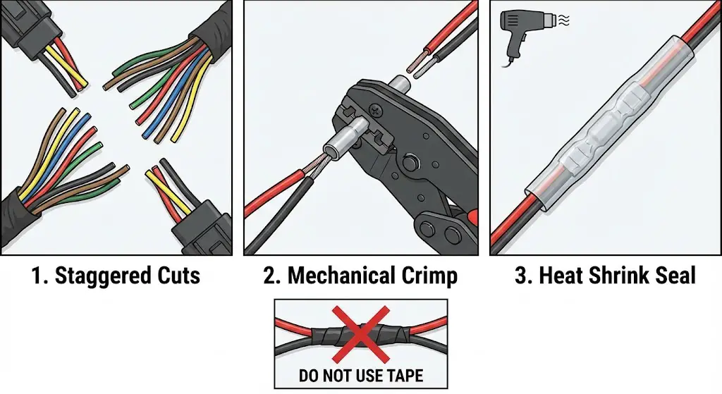
Ford's official engineering service documentation explicitly and repeatedly prohibits the use of simple twisted wire connections wrapped in standard electrical tape. Such connections vibrate loose, oxidize rapidly, and create massive voltage drops. Furthermore, standard acid-core plumbing solder must absolutely never be utilized on automotive wiring harnesses, as the acidic flux induces severe, unstoppable galvanic corrosion that will eat through the copper stranding from the inside out.
When executing the replacement of a melted or damaged ignition switch pigtail, technicians must adhere to a strict, rigorous protocol to maintain factory integrity:
- Total System De-Energization: Always begin by disconnecting the negative battery cable. This is not merely a suggestion; failing to do so risks the accidental, explosive deployment of the steering wheel airbag system (SRS) and guarantees the short-circuiting of unfused, high-amperage lines directly to the steering column shaft.
- Staggered Wire Splicing Geometry: When splicing a multi-wire, high-density pigtail, the technician must meticulously cut the factory harness wires at staggered, offset lengths. If all wires are cut at the exact same location, the resulting cluster of splice joints will form a massive, inflexible bulge in the harness. This bulge will inevitably chafe against the moving components of the steering column or the plastic clam-shell cover, eventually wearing through the insulation and causing a catastrophic mass short circuit.
- Mechanical Crimping vs. Chemical Soldering: While careful rosin-core soldering creates an excellent, low-resistance joint perfectly suited for delicate CAN bus data lines, the high-vibration environment of a steering column structure often strongly favors professional-grade mechanical crimping for heavy-gauge power wires. A high-quality ratcheting crimp tool must be used in conjunction with uninsulated, seamless butt connectors to ensure maximum mechanical compression and physical pull-strength.
- Environmental Sealing: Every single splice joint must be hermetically sealed and covered with dual-wall, adhesive-lined heat shrink tubing. The technician must utilize a shielded electronic heat gun to apply focused heat until the internal marine-grade adhesive melts completely and flows out of both ends of the tubing. This process creates a permanent, waterproof, oxygen-free, and vibration-resistant strain relief seal. For standard 14 to 16 AWG ignition wires, Motorcraft officially specifies the use of part number WT-56815 heat shrink tubing to maintain OEM compliance.
- Diligent Color Matching and Circuit Tracing: A dangerous pitfall involves trusting aftermarket replacement parts blindly. Replacement aftermarket pigtails frequently utilize uniform, generic wire colors (for example, utilizing all black or all white wires) rather than matching Ford's complex, striped factory color codes. It is absolutely imperative to physically trace the pinout location of every single wire on the new pigtail back to its corresponding location on the melted factory harness connector, rather than attempting to rely blindly on color matching. For instance, discussions regarding classic Bronco restorations frequently highlight the immense danger of accidentally crossing the Red/Green primary ignition wire with the Black/Green accessory wire simply due to aftermarket pigtail manufacturing discrepancies. Reversing these wires can result in an engine that refuses to shut off when the key is removed, or an accessory circuit that continuously drains the battery overnight.


