Ford Fiesta Coil Pack Wiring Diagram: Easy Setup Guide
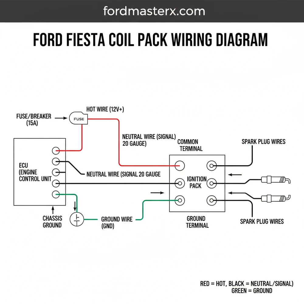
A Ford Fiesta coil pack wiring diagram illustrates the electrical circuit between the engine control unit and the ignition system. It identifies the 12V power supply, ground connections, and signal wires for each cylinder. By mapping these paths, you can diagnose spark issues, verify voltage, and ensure the engine fires in the correct sequence.
📌 Key Takeaways
- Accurately identifies pinouts for ignition timing and misfire troubleshooting.
- The common terminal is the most critical point for providing consistent power.
- Always disconnect the battery before testing high-voltage ignition components to ensure safety.
- Use a digital multimeter to check the hot wire for 12V during the ‘On’ position.
- Reference this diagram when you encounter P0300 misfire codes or rough idling.
Navigating the electrical system of a modern vehicle can be daunting, especially when dealing with the ignition system. If your vehicle is experiencing misfires, a rough idle, or a decrease in fuel efficiency, understanding the ford fiesta coil pack wiring diagram is the first step toward a successful DIY repair. This guide provides a comprehensive breakdown of the wiring harness, terminal identifications, and color codes necessary to diagnose or replace your ignition components. By the end of this article, you will be able to identify each wire’s function, measure voltage accurately, and ensure your engine’s firing sequence remains perfectly synchronized for optimal performance.
The Ford Fiesta typically utilizes a “wasted spark” ignition system or individual coil-on-plug (COP) units depending on the specific engine variant (such as the Duratec or EcoBoost). The wiring diagram acts as a map to ensure the Powertrain Control Module (PCM) can send the correct timed pulse to the right cylinder.
The main diagram for a Ford Fiesta coil pack focuses on the electrical connector that plugs into the ignition coil. In most standard four-cylinder configurations, you will find a multi-pin connector. The layout is designed to handle high-frequency signals and consistent power delivery. A critical component of the diagram is the identification of the hot wire, which provides the constant 12-volt supply from the battery via the ignition relay. This is usually the common terminal in many Ford wiring harnesses, often located in the center pin of a three-pin connector.
Visually, the diagram illustrates the path from the fuse box to the coil and then to the PCM. The traveler wire (or signal wire) acts as the communication bridge between the engine’s computer and the coil pack. For a wasted spark system, you will see two signal wires: one for cylinders 1 and 4, and another for cylinders 2 and 3. The gauge of these wires is specifically chosen to minimize resistance while handling the rapid switching of current. If the wire gauge is too thin or the insulation is compromised, the voltage drop can lead to a weak spark and engine hesitation. Additionally, the diagram highlights the ground wire or the path to the chassis, which ensures the circuit is completed safely.
– Ford Fiesta Coil Pack Wiring Diagram: Illustrating Pin 1 (Trigger A), Pin 2 (12V Power/Hot Wire), and Pin 3 (Trigger B) with corresponding color codes and PCM connections.
Understanding the color-coding is essential. While colors can vary slightly based on the manufacturing plant, a common scheme for the Fiesta involves a solid green or blue wire for the signal paths and a red or orange stripe for the power supply. The diagram also specifies the neutral wire equivalent in automotive DC systems—the return path to the battery negative or engine block. Unlike household wiring where you might look for a brass screw to identify a hot connection, automotive connectors use keyed plastic housings and metallic pins to ensure a secure, moisture-resistant fit.
Interpreting a ford fiesta coil pack wiring diagram requires a methodical approach to ensure you don’t accidentally short the PCM. Follow these steps to read and apply the diagram information for your repair or diagnostic project:
- ✓ Step 1: Identify the Connector Orientation – Hold the coil pack connector with the locking tab facing upward. This establishes the standard “pin 1” position, usually on the far left.
- ✓ Step 2: Locate the Common Terminal – Use your diagram to find the 12V supply pin. On most Fiesta models, this is the center pin. This wire provides the “hot” energy required to create the spark.
- ✓ Step 3: Trace the Traveler Wires – Identify the signal wires coming from the PCM. These wires “travel” from the computer to the coil to tell it exactly when to fire. Ensure these are connected to the correct trigger pins according to the firing order.
- ✓ Step 4: Verify Wire Gauge and Integrity – Inspect the thickness of the wires. If you are repairing a harness, you must use the same gauge wire to prevent overheating. Look for frayed insulation or “green crusties” (corrosion) near the terminals.
- ✓ Step 5: Test for Voltage – With the ignition in the ‘ON’ position (engine off), use a multimeter to check for 12.6V at the hot wire pin. This confirms the fuse and relay are functioning.
- ✓ Step 6: Confirm Grounding – Ensure the ground wire or the mounting bracket (if used as a ground) has a clean, metal-to-metal contact. A poor ground is a leading cause of coil failure.
- ✓ Step 7: Final Continuity Check – Use the “beep” setting on your multimeter to ensure there is a continuous path from the connector pins back to the PCM harness.
Never test the coil pack wires while the engine is cranking unless you are using specialized automotive diagnostic tools. The secondary ignition voltage can reach upwards of 30,000 volts, which can cause severe injury or damage sensitive electronics.
When the actual wiring does not match the ford fiesta coil pack wiring diagram, you are likely looking at a common issue such as harness degradation or a previous “hack job” repair. One frequent problem is “cross-talk” between wires, where the insulation of the traveler wire and the hot wire melts together due to engine heat. This causes the coil to fire at the wrong time or stay “on” constantly, leading to a melted coil pack casing. If you see discoloration near the common terminal, it usually indicates excessive resistance and heat buildup.
Another common issue is a “floating ground.” In this scenario, the neutral wire or ground path has high resistance, causing the current to seek alternative paths through the sensors, which can trigger multiple unrelated error codes. Warning signs include a Check Engine Light (CEL) with codes P0300, P0301, or P0351. If you find that the voltage at the connector is significantly lower than the battery voltage, check for a blown ignition fuse or a faulty relay in the engine bay power distribution center. If the wiring appears intact but the spark is still missing, the PCM’s internal ignition driver may have failed, necessitating professional repair.
When reconnecting the harness to the coil pack, apply a small amount of dielectric grease to the plastic connector housing (not the metal pins themselves). This prevents moisture ingress and makes future removal much easier without breaking the brittle plastic clips.
To ensure long-term reliability after using the ford fiesta coil pack wiring diagram for a repair, always prioritize high-quality components. When replacing the coil, choose OEM or reputable high-performance brands. Cheap aftermarket coils often have different internal resistance, which can stress the factory traveler wire and eventually damage the PCM. Furthermore, ensure the wiring harness is routed away from high-heat areas like the exhaust manifold. Using heat-reflective loom or sleeve can extend the life of your wiring significantly.
Maintenance is also key. Periodically inspect the common terminal for any signs of backing out from the plastic connector. If a pin feels loose, it may need to be de-pinned and tightened. For those looking to save costs, diagnosing the wiring yourself using the diagram is the best way to avoid “parts cannon” repairs—replacing expensive coils when the real culprit was simply a broken ground wire. Keep your electrical connections clean and dry, and your Ford Fiesta will continue to deliver reliable ignition performance for miles to come. By mastering the ford fiesta coil pack wiring diagram, you empower yourself to handle one of the most vital systems in your vehicle with confidence and precision.
Step-by-Step Guide to Understanding the Ford Fiesta Coil Pack Wiring Diagram: Easy Setup Guide
Identify the coil pack location and disconnect the negative battery cable to prevent electrical shorts.
Locate the electrical connector and inspect the common terminal for signs of corrosion or burnt pins.
Understand how the traveler wire transmits the pulse signal from the ECU to the specific coil tower.
Connect a multimeter to the ground wire and hot wire to ensure the circuit is receiving full battery voltage.
Verify that each spark plug wire is seated firmly and that the neutral wire path is clear of obstructions.
Complete the installation by clearing any stored OBD-II codes and performing a test drive to confirm the fix.
Frequently Asked Questions
Where is the Ford Fiesta coil pack located?
On most Ford Fiesta models, the coil pack is mounted on the side or top of the cylinder head near the spark plugs. It is typically a black rectangular block with thick spark plug wires extending from it. You can follow these cables back from the engine to locate the unit.
What does a Ford Fiesta coil pack wiring diagram show?
The diagram provides a visual map of the electrical circuit, including the traveler wire pathways from the PCM to the ignition coil. It details the ground wire location and the hot wire power source, allowing technicians to verify that each cylinder receives the correct signal for efficient combustion.
How many wires does the Ford Fiesta coil pack have?
Most Ford Fiesta coil packs utilize a three or four-wire connector. This configuration includes a 12V hot wire for power, a ground wire for circuit completion, and signal wires that act as a traveler wire to trigger specific coils based on the engine’s precise firing order and timing.
What are the symptoms of a bad Ford Fiesta coil pack?
Common symptoms include engine misfiring, a noticeable rough idle, reduced fuel economy, and difficulty starting. You may also see a flashing ‘Check Engine’ light. A faulty common terminal or broken internal wiring can cause a complete lack of spark, leading to a dead cylinder and poor performance.
Can I replace the Ford Fiesta coil pack myself?
Yes, replacing the coil pack is a manageable DIY task. By using a wiring diagram to ensure the neutral wire and signal connections are properly seated, you can swap the unit with basic hand tools. Just ensure the spark plug wires are reconnected in the correct order to avoid timing issues.
What tools do I need for coil pack testing?
You will need a digital multimeter to test the hot wire for 12V power and a spark tester to check output. A basic socket set is required to remove mounting bolts. A wiring diagram is essential to help you identify which pin serves as the common terminal during testing.


