Ford F350 Air Conditioning Diagram: System Guide
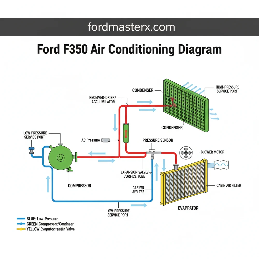
A Ford F350 air conditioning diagram illustrates the system structure, including the compressor, condenser, evaporator, and accumulator. It maps the refrigerant flow and component layout to help identify high and low-pressure lines. Understanding this configuration is essential for troubleshooting leaks, electrical faults, or mechanical failures in your heavy-duty truck’s cooling system.
📌 Key Takeaways
- Visualizes the refrigerant path and component layout
- Identify the AC compressor as the heart of the system
- Maintain safety by identifying high-pressure service ports
- Use the diagram to trace refrigerant leaks effectively
- Refer to this guide during component replacement or recharge
When you are facing a sweltering summer day and your heavy-duty truck is blowing warm air, understanding the Ford F350 air conditioning diagram becomes a top priority. This visual map is more than just a technical drawing; it is a critical diagnostic tool that bridges the gap between a broken cooling system and a comfortable cabin. Whether you are a dedicated DIY enthusiast or a professional technician, having a clear layout of the refrigerant lines, electrical connections, and sensor locations is vital for efficient repair. In this comprehensive guide, we will break down the entire system, from the mechanical structure to the complex electrical schematic, ensuring you have the knowledge to restore your vehicle’s climate control.
Understanding the Ford F350 Air Conditioning System Layout
The Ford F350 utilizes a high-capacity air conditioning system designed to cool a large cabin while under significant engine load. The system configuration is generally divided into two distinct parts: the mechanical refrigerant loop and the electrical control circuit. In the mechanical diagram, you will see a continuous loop that begins and ends at the compressor. This component is the heart of the system, responsible for pressurizing the refrigerant. The high-pressure side of the blueprint typically includes the condenser, located at the very front of the vehicle to maximize airflow, and the orifice tube or expansion valve, which acts as a gateway to the low-pressure side.
The low-pressure side of the diagram features the evaporator, housed within the dashboard’s heater core box, and the accumulator or receiver-drier. The accumulator is a crucial component in many F350 models, acting as a filter and moisture-remover to protect the compressor from liquid slugging. When looking at a technical schematic, these parts are often color-coded; red lines represent the high-pressure, high-temperature vapor and liquid, while blue lines represent the low-pressure, cool vapor.
Electrically, the system is governed by a series of switches and relays. The overview of the electrical schematic will show the AC clutch relay, the high-pressure cutout switch, and the low-pressure cycling switch. On modern F350 trucks, the Powertrain Control Module (PCM) also appears in the diagram. The PCM monitors engine temperature and throttle position, meaning it can “veto” the air conditioning if it senses the engine is overheating or under extreme stress. Understanding this integration is essential, as a cooling problem may sometimes be an electrical communication issue rather than a mechanical failure.
The Ford F350 often uses a “Cycling Orifice Tube” system. This means the compressor does not run constantly but cycles on and off based on the pressure readings from the low-pressure switch to prevent the evaporator from freezing over.
[DIAGRAM_PLACEHOLDER: Ford F350 AC System Schematic showing Compressor, Condenser, Evaporator, and Electrical Relay Logic]
Step-by-Step Guide to Reading and Interpreting the Diagram

Interpreting a Ford F350 air conditioning diagram requires a systematic approach. To successfully diagnose or install components, follow these steps to ensure you are reading the blueprint correctly.
- ✓ Identify the Power Source: Start at the battery or the Central Junction Box (fuse box) on the schematic. Look for the fuse dedicated to the AC system.
- ✓ Trace the Signal Path: Follow the line from the AC request switch on the dashboard to the PCM or the AC clutch relay. This tells you if the “request” to turn on the air is reaching the controller.
- ✓ Locate Safety Switches: Find the high and low-pressure switches. These are usually wired in series. If one is “open” due to incorrect pressure, the power will never reach the compressor clutch.
- ✓ Observe the Grounding Points: Every electrical component needs a ground. Check the diagram for the “G” labels (e.g., G102) to see where the compressor clutch or blower motor connects to the vehicle frame.
- ✓ Match Wire Colors: Ford uses specific color-coding (e.g., LB/PK for Light Blue/Pink). Cross-reference the diagram’s legend with the actual wires in your engine bay to ensure you are testing the right circuit.
- ✓ Map the Physical Components: Transition from the electrical schematic to the physical layout. Locate where the hoses enter the firewall and where the compressor sits on the serpentine belt drive.
Air conditioning systems operate under extremely high pressure. Never disconnect a refrigerant line without first having the system professionally evacuated. Venting refrigerant into the atmosphere is illegal and dangerous.
To perform these tasks, you will need a few essential tools:
1. A digital multimeter for testing electrical continuity and voltage.
2. A set of manifold gauges to monitor the high and low-side pressures.
3. A bright work light to identify component labels under the hood.
4. A piercing probe or back-probe pins for testing wires without damaging the insulation.
Common Issues & Troubleshooting Using the Diagram

The Ford F350 air conditioning diagram is your best friend when troubleshooting the most frequent failures. One of the most common complaints is the compressor clutch failing to engage. By using the schematic, you can quickly determine if the issue is a blown fuse, a faulty relay, or a tripped safety switch. If you have power at the relay but not at the compressor, the diagram will point you toward the high-pressure cutout switch located near the condenser or the low-pressure switch on the accumulator.
Another frequent issue is intermittent cooling. This often points to a “cycling” problem. If the diagram shows the low-pressure switch is responsible for cycling, you can test that specific switch to see if it is opening too early. Furthermore, if you notice the blower motor works on high but not on lower speeds, the electrical blueprint will lead you to the blower motor resistor, which is usually found tucked inside the HVAC ducting.
If your AC is blowing warm air, check the “air gap” on your compressor clutch. Over time, the clutch plate wears down, and the magnetic pull can no longer close the gap. A quick check of the schematic will confirm if the clutch is receiving the 12V signal it needs to engage.
Tips & Best Practices for AC Maintenance
Maintaining the air conditioning system in an F350 requires attention to detail. Because these trucks are often used for towing or off-road work, the condenser is prone to becoming clogged with dirt, bugs, or debris. Use the system overview to locate the condenser and regularly spray it out with a low-pressure garden hose to maintain heat exchange efficiency.
When replacing components, always ensure you are using the correct lubricant. Most F350 compressors require specific PAG (Polyalkylene Glycol) oil. Refer to your vehicle’s specific configuration to find the correct viscosity. Additionally, never skip the “vacuum” stage when the system has been opened. Using a vacuum pump to remove moisture and air is the only way to ensure the new refrigerant performs correctly and doesn’t cause internal corrosion.
For long-term reliability, consider replacing the cabin air filter every 15,000 miles. A clogged filter restricts airflow across the evaporator, which can lead to the system freezing up and potentially damaging the compressor. If you find yourself frequently adding refrigerant, do not simply use “stop-leak” products. These can clog the small passages in the condenser and orifice tube shown in your diagram. Instead, use the schematic to trace the lines and look for oily spots, which indicate a refrigerant leak that needs a mechanical fix.
By following the Ford F350 air conditioning diagram and adhering to these maintenance best practices, you can ensure that your truck remains a cool and comfortable environment, no matter how harsh the external conditions may be. Proper diagnosis starts with a good map; keep this guide and your diagram handy for any future repairs.
Frequently Asked Questions
Where is the AC compressor located?
The Ford F350 AC compressor is typically located on the front of the engine, driven by the serpentine belt. Depending on your engine model, it is often mounted on the passenger side near the top or bottom, allowing it to compress refrigerant and circulate it through the entire system structure.
What does this diagram show?
This diagram shows the complete Ford F350 air conditioning system configuration, highlighting the path refrigerant takes between the compressor, condenser, orifice tube, and evaporator. It serves as a visual guide to help you trace lines, identify electrical connectors, and understand the mechanical layout for effective maintenance and repair.
How many lines are in the AC configuration?
The standard F350 configuration features two primary refrigerant lines: the high-pressure discharge line and the low-pressure suction line. Additionally, the system includes electrical connections for the compressor clutch, high-pressure cutout switch, and the low-pressure cycling switch, all of which are critical for the system to function correctly.
What are the symptoms of a bad AC component?
Common symptoms of a failing AC component include blowing warm air, unusual grinding noises when the system is engaged, or visible refrigerant leaks. If the compressor clutch fails to engage or the system frequently cycles on and off, it often indicates an electrical issue or a low refrigerant charge.
Can I replace the AC compressor myself?
Replacing basic parts like the pressure switch is feasible for DIYers. However, replacing the compressor or evaporator requires specialized equipment to recover refrigerant, pull a vacuum, and recharge the system. Due to environmental regulations and safety risks, professional assistance is recommended for any task involving opening the sealed lines.
What tools do I need for troubleshooting?
For basic diagnosis using the Ford F350 air conditioning diagram, you will need a manifold gauge set to monitor pressures and a thermometer for vent temps. For repairs, a standard socket set, a line disconnect tool kit, and a vacuum pump are essential to ensure the system is moisture-free.


