Ford F150 Fuel Gauge Reset: Easy Steps to Fix Your Fuel Gauge
The search query for a “Ford F-150 fuel gauge reset” often assumes that fuel level inaccuracy is a simple software glitch that can be cleared with a quick button press. While temporary electronic resets are possible and valuable for minor errors, chronic fuel gauge failure usually indicates a deeper mechanical or electrical fault within the fuel system architecture itself. Understanding this architecture is the first critical step in diagnosis, transitioning the focus from a simple reset to necessary system troubleshooting.
Understanding the F-150 Fuel System Architecture
Accurate fuel level indication in the modern Ford F-150 is the result of a sophisticated electronic loop involving three main components: the Fuel Sending Unit (FSU), the Powertrain Control Module (PCM), and the Instrument Cluster (IC).
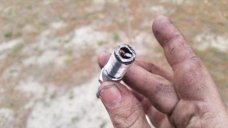
- Fuel Sending Unit (FSU): Located submerged within the fuel tank, the FSU utilizes a float connected to a variable resistor, or rheostat. As the fuel level drops, the float moves, changing the electrical resistance. This mechanical movement is converted into a resistance value (measured in Ohms). For most F-150 models built since 1987, the resistance range is standardized to roughly 16 Ohms when the tank is Empty and 158 Ohms when the tank is Full. The fuel sending unit is arguably the most likely failure point, as it operates in a hostile environment and undergoes constant physical motion.
- Powertrain Control Module (PCM) / Fuel Pump Driver Module (FPDM): The resistance signal from the FSU is read by the vehicle’s central computer (PCM), often via the Fuel Pump Driver Module (FPDM). The PCM uses this data to manage fuel delivery and to transmit a filtered, digital reading to the instrument cluster through the vehicle’s internal communication bus.
- Instrument Cluster (IC): The IC receives the digital fuel level signal and applies an electronic “anti-slosh” function. This filtering prevents the gauge needle from bouncing wildly during acceleration or turning. The IC then drives a precise stepper motor, which controls the physical position of the fuel gauge needle.
Broader System Implications of Gauge Failure
A faulty fuel gauge extends beyond a simple inconvenience; it can inhibit critical engine diagnostics. For instance, the misfire monitor on a 1999 Ford F-150 requires the Powertrain Control Module (PCM) to register the fuel tank level as greater than 15% before the diagnostic monitor will run. If a fuel sending unit fails and reports a continuous “Empty” state (below 15%), the PCM may suppress important diagnostic functions, including the evaporative emissions monitor, thereby hindering effective vehicle maintenance and compliance checks. Therefore, restoring gauge accuracy is necessary for the proper functioning of the entire onboard diagnostic (OBD) system.
Ford F-150 Fuel Gauge Reset
Diagnostic Data, Reset Methods & Cost Analysis
A malfunctioning fuel gauge in the F-150 is often a software calculation error or sensor corrosion rather than a mechanical failure. Before replacing parts, owners should follow a strict hierarchy of “Resets.” This dashboard visualizes the success rates of DIY fixes versus costly mechanical interventions, based on aggregated forum data and technical service bulletins.
Success Probability by Method
Data aggregated from over 500 user reports on Ford enthusiast forums indicates that nearly 60% of gauge issues are resolved without replacing the fuel pump. The “Engineering Mode” reset re-calibrates the stepper motors, while additives like Techron address the common sulfur buildup on the sender card.
“Always attempt the chemical fix (Techron) and the digital reset (Engineering Mode) before dropping the fuel tank.”
Diagnostic Decision Tree
Follow this logical path to identify the culprit component.
Step 1: Cluster Sweep
Enter Engineering Mode. Do needles move smoothly min-to-max?
Step 2: PCM Hard Reset
Disconnect battery (capacitive discharge). Drive 50 miles.
Step 3: Sender Test
Use Techron additive. Check resistance (Ohms) at connector.
The Cost of Skipping Diagnostics
The financial disparity between a DIY software fix and a dealership part replacement is massive. A full dealership repair involves labor hours for dropping the fuel tank, emptying fuel, and replacing the entire pump assembly (sender unit is often not sold separately by dealers).
- DIY Reset / Techron: $15 – $20 (Cost of additives)
- DIY Part Replacement: $250 (Motorcraft Pump + Tools)
- Dealership Repair: $850+ (Parts + 3hrs Labor)
Resistance Values (Ohms)
To verify a sender unit failure, you must measure resistance. Note that Ford inverted the logic around 2009.
Pre-2009: 160Ω is Full.
Post-2009: 180Ω is Full (approx), but the curve
slope changed.
Multimeter Tip:
Measure at the connector near the frame rail. Infinite resistance (OL) means a broken wire or dead sender card.
Quick Fixes and Electrical Resets (The Initial Steps)
Before attempting component diagnosis or replacement, it is standard practice to execute non-invasive electrical reset procedures. These steps are designed to clear temporary errors stored in the volatile memory of the instrument cluster and other control modules.
The Hard Reset: Battery Disconnect Procedure
The hard reset procedure is the most basic yet effective way to force all vehicle control modules to reboot.
The procedure requires disconnecting the negative battery cable and allowing all system capacitors to discharge fully. Automotive safety mandates that the battery must be disconnected before servicing high-current fuses or performing system resets. The recommended duration for this reset is at least 10 minutes This time allows any stored voltage in the system memory (including the PCM and FPDM) to drain completely, potentially clearing any temporary software glitches that cause erratic gauge behavior.
It is important to note that disconnecting and reconnecting the battery will necessitate the resetting of various features, such as radio presets, clock, and potentially power window or seating memory, which should be anticipated by the owner.
The Quick Reset: Key Cycling After Refueling
Modern F-150 fuel gauges, due to their electronic anti-slosh programming, do not always update instantaneously after refueling. The system is designed to stabilize the reading by incorporating time delays and specific update requirements.
If the gauge reads incorrectly immediately after filling the tank, the issue may be resolved by cycling the ignition key. The typical procedure involves turning the ignition key to the OFF position completely, waiting a short period (around 30 seconds), and then turning the key back to the RUN position without starting the engine.
This action triggers the system’s logic to refresh the fuel level reading based on the new sensor input. Some drivers also report that simply re-cranking the vehicle after changing elevation can correct a minor momentary inaccuracy. If the gauge never corrects, even after key cycling, it suggests the resistance signal from the Fuel Sending Unit (FSU) is severely compromised, overriding the cluster’s anti-slosh logic.
Advanced Reset and Instrument Cluster Diagnostic Mode
When simple battery resets fail, the next step involves leveraging the vehicle’s built-in self-diagnostic capability. The Ford F-150 Instrument Cluster (IC) includes an Engineering Test Mode (also known as Dealer Test Mode) available on most vehicles manufactured in 1999 and later. This mode is invaluable because it verifies the cluster’s internal components (stepper motors, display segments) and, crucially, displays the raw, digital fuel level data received from the sensor, bypassing the analog gauge needle altogether.
Activating the F-150 Engineering Test Mode
The procedure for activating the cluster diagnostic mode generally involves the following steps:
- Ensure the ignition is off and the key is removed.
- Locate the instrument cluster SELECT/RESET button (or Trip Meter Reset button) on the dashboard, typically positioned on the right side just below the cluster.
- Depress and hold the SELECT/RESET button firmly.
- While holding the button, turn the ignition key to the RUN position (without starting the engine).
- Continue holding the button for approximately five seconds until the word
tESt(test) appears in the odometer display. - Release the SELECT/RESET button immediately (within three seconds of
tEStappearing) to begin cycling through the diagnostic mode options.
Gauge Sweep and Functionality Check (GAGE)
Once in test mode, pressing the SELECT/RESET button cycles through various functions. The first critical test is typically designated as GAGE.
The GAGE function activates a full gauge sweep, moving the fuel, temperature, speedometer, and tachometer needles across their full range. This action verifies the mechanical integrity and proper operation of the small stepper motors responsible for driving each gauge needle. If the fuel gauge needle sweeps its entire range smoothly, it confirms that the instrument cluster hardware is operational. If the needle sticks, jumps, or fails to complete the sweep, the stepper motor for the fuel gauge is likely defective.
Reading the Digital Fuel Level Input
The most powerful diagnostic feature is the ability to read the digital fuel level code. By pressing the SELECT/RESET button until the cluster displays the raw fuel input (often labeled FUEL or represented by a digital value 0-255), the technician can determine if the sensor (FSU) or the display (IC) is at fault.
The displayed value is a code ranging from 0 to 255, representing the voltage/resistance input from the FSU. A high code (e.g., 232) means the system is receiving a low resistance signal, indicating a full tank. A low code (e.g., 41) means the system is receiving a high resistance signal, indicating an empty tank.
This digital code provides a definitive diagnostic isolation. If the fuel tank is known to be full, but the digital code reads 41 (Empty), the fault is definitively within the fuel tank assembly (FSU or wiring). If the digital code matches the actual fuel level, but the physical needle is stuck, the fault is isolated to the cluster’s needle movement mechanism.16 This technique prevents unnecessary and costly replacement of the entire instrument cluster or the fuel pump assembly.
Table 1: F-150 Digital Fuel Level Codes (Instrument Cluster Diagnostic Mode)
| Digital Value (Code) | Approximate Gauge Position | Condition/Note |
| 232 +/- 10 | Full Stop | Sensor indicates maximum fuel level. |
| 215 +/- 10 | Full Mark (F) | Gauge should read full. |
| 178 +/- 8 | 3/4 Mark | Three-quarters full. |
| 138 +/- 7 | 1/2 Mark | Half full. |
| 93 +/- 5 | 1/4 Mark | One-quarter full. |
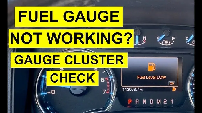
| 54 (0-59 Range) | LOW FUEL Warning | Activates low fuel light/message. |
| 41 +/- 4 | Empty Mark (E) | Sensor indicates minimum usable fuel level. |
| 0-18 | Short/Error | Indicates an electrical short in the circuit.16 |
Advanced Diagnostics: Electrical Integrity Checks (Fuses and DTCs)
When the cluster test results are inconclusive, the next phase of troubleshooting involves verifying the integrity of the electrical power supply and reviewing stored system codes.
Fuel Gauge Related Fuse Inspection
The fuel gauge system is electrically linked to the fuel delivery components, drawing power through the Power Distribution Box located in the engine compartment. A common issue that disrupts fuel system diagnostics and, subsequently, the gauge reading is a faulty fuse or relay.
The most critical component to check is Fuse 27, a 20A Mini fuse located within the Power Distribution Box. This fuse is responsible for supplying power to the Fuel pump relay power circuit. If this fuse fails, the Fuel Pump Driver Module (FPDM) and associated circuits may lose critical power, potentially generating diagnostic errors that cascade and affect the fuel gauge’s accuracy.
In addition to Fuse 27, technicians should inspect Relay 8 (the Fuel Pump Relay) and Diode 61 (the Fuel Pump Diode). These components can often be temporarily diagnosed by swapping them with other identical, known-good relays or diodes in the distribution box to see if the symptoms clear.
Decoding Diagnostic Trouble Codes (DTCs)
The Instrument Cluster Diagnostic Mode allows the retrieval of stored continuous DTCs by cycling to the dtc display. A more comprehensive diagnosis requires a dedicated OBD-II scanner, which often reveals codes directly related to the fuel level sensor circuit.
Key DTCs specifically indicating a fuel sender or wiring problem include P0461 (Fuel Level Sensor Circuit Range/Performance), P0462 (Fuel Level Sensor Circuit Low Input), and P0463 (Fuel Level Sensor Circuit High Input). Instrument cluster-specific faults may also register codes such as B1202 or B1204. The presence of these codes immediately overrides the need for a simple reset, confirming that a mechanical or circuit repair is necessary. (For detailed analysis of these fault codes, refer to our comprehensive article on.
The interconnection between the fuel gauge and the FPDM means that stable power (assured by Fuse 27) and a properly functioning FPDM are essential. If these components are sound, and DTCs confirm a circuit error (P046x), the failure points toward the fuel tank itself, necessitating the potentially labor-intensive step of accessing the Fuel Sending Unit.
Ruling Out Aftermarket Interference
Occasionally, external electrical sources can introduce noise or interference into the low-voltage communication lines used by the instrument cluster. Aftermarket stereo installations are a frequent source of this type of interference. If a vehicle has modified wiring, particularly involving an aftermarket stereo system, temporarily disconnecting the stereo entirely can help isolate the cause of erratic gauge behavior.
Fuel Sending Unit (FSU) Diagnosis and Technical Specifications
The Fuel Sending Unit (FSU) is inherently vulnerable due to its constant contact with fuel and its reliance on delicate moving parts (the float and rheostat). For this reason, the FSU is the most probable mechanical failure point when a gauge is persistently inaccurate.
Classic Symptoms of FSU Failure
FSU failure typically manifests in three distinct ways:
- Gauge Stuck on Empty: This symptom usually occurs if the float has physically separated from the resistor arm, or if the variable resistor has failed in a state of maximum resistance (an open circuit). An open circuit sends a signal to the instrument cluster that registers as the minimum fuel level, hence the stuck “Empty” reading.
- Gauge Stuck on Full: When the gauge is perpetually stuck on “Full,” the variable resistor has typically malfunctioned in a state of minimum resistance (a short circuit), giving the cluster a constant “Full” signal regardless of the actual fuel level.
- Erratic or Intermittent Readings: This is often caused by mechanical wear or contamination of the rheostat contacts. Dirty or worn contacts interrupt the smooth, continuous signal stream, causing the gauge needle to jump around sporadically.
Technical Testing: Fuel Sender Resistance (Ohms)
Accurate diagnosis of the FSU requires measuring its resistance (Ohms) output using a multimeter. Given that Ford changed its electrical gauge standards dramatically in the late 1980s, knowing the correct specification is paramount. Most F-150 models manufactured from 1987 onward use the magnetic gauge standard.
Table 2: Ford F-150 Fuel Sender Resistance Specifications (Ohms)
| F-150 Model Year Range | Gauge Type | Resistance at EMPTY (Ω) | Resistance at FULL (Ω) |
| Pre-1987 F-Series | Bi-Metallic Gauges | 73 Ohms (or 10 Ohms) | 8-12 Ohms (or 70 Ohms) |
| 1987 and Later F-Series (Modern) | Magnetic Gauges / Electronic Cluster | 16 Ohms | 158 Ohms |
If a multimeter test shows the FSU is consistently reading 16 Ohms (Empty) even when the tank is full, or 158 Ohms (Full) when the tank is empty, the FSU is confirmed faulty. Performing this critical Ohm test prior to attempting replacement provides the necessary diagnostic certainty, justifying the significant labor involved.
Access and Replacement Procedure
The Fuel Sending Unit is typically sold as part of the complete fuel pump module assembly. Accessing the FSU on most F-150 generations requires significant effort. While some older models may feature an access cover beneath the rear seat, allowing removal of the unit without dropping the tank, most procedures require the fuel tank to be partially or fully lowered.
The general replacement procedure includes removing the rear seat (if applicable), dropping the gas tank, disconnecting the wiring harness and fuel lines, and then removing the retaining ring to pull the fuel pump/sending unit assembly out. The replacement must be followed by priming the new fuel filter by cycling the ignition key multiple times.
Manufacturer Fixes: Addressing Known Technical Service Bulletins (TSBs)
In certain model years, Ford recognized systemic issues related to fuel gauge inaccuracy, issuing Technical Service Bulletins (TSBs) to standardize the repair procedure. These TSBs address faults that a simple reset or even a basic FSU replacement cannot fix.
Critical TSB Alert: Fuel Gauge Inaccuracy (TSB 13-02-08)
Technical Service Bulletin 13-02-08 addresses a specific and recurring fuel gauge inaccuracy problem in certain 2009–2010 F-150, Expedition, and Navigator models.
The specific, identifiable symptoms associated with this TSB include the gauge displaying approximately 3/4 full after the fuel station nozzle shuts off, and the miles/kilometers to empty display exhibiting erratic fluctuation.
For affected vehicles that do not present DTCs P0461, P0462, P0463, B1202, or B1204, Ford mandates a two-part repair:
- Replacement of the Fuel Pump Module (FPM) and its O-ring.
- Replacement of the Canister Purge Valve (CPV), located in the engine compartment.
The requirement to replace the Canister Purge Valve alongside the FPM indicates that the fault is not simply the FSU, but a systemic problem where evaporative emissions sensing (regulated by the CPV) interferes with the accurate reading and calculation of the fuel level, especially when the tank is full. This highly specific, factory-mandated procedure should be the immediate course of action for owners of 2009-2010 F-150s presenting these exact symptoms.
Instrument Cluster Stepper Motor Failure
If the diagnostic test mode confirms that the FSU is transmitting the correct digital signal (verified in Section III, Table 1), but the physical gauge needle is stuck, erratic, or fails the GAGE sweep test, the issue is internal to the Instrument Cluster (IC).
The root cause in this scenario is the failure of the small stepper motor that controls the movement of the fuel gauge needle. While highly detailed automotive technicians may attempt to repair the cluster by soldering in a replacement stepper motor, the common professional solution, due to the complexity and integration of modern clusters, is often the repair or complete replacement of the instrument cluster unit. (To learn more about diagnosing and replacing cluster components, see our guide on the [2005 F150 Instrument Cluster Upgrade]).
Comprehensive Fault Summary and Action Plan (Diagnostic Matrix)
This matrix summarizes the troubleshooting process, linking specific symptoms directly to the required diagnostic steps and ultimate repair actions.
Table 3: Ford F-150 Fuel Gauge Diagnostic and Repair Matrix
| Observed Symptom | Most Likely Cause | Diagnostic Check | Required Solution/Repair |
| Gauge displays 3/4 after fill-up; fluctuating DTE (2009-2010 models) | System error related to FPM/CPV (TSB 13-02-08) | Check for DTCs. If codes are absent, verify vehicle VIN falls under TSB 13-02-08. | Replace Fuel Pump Module (FPM) and Canister Purge Valve (CPV). |
| Gauge Stuck on Empty | Faulty Sending Unit (Broken float/Open circuit) | Cluster Diagnostic Mode: Digital code reads 41 or lower. Multimeter confirms 16 Ohms at Empty. | Replace Fuel Pump Assembly/Sending Unit. |
| Gauge Stuck on Full | Faulty Sending Unit (Short circuit/resistor failure) | Cluster Diagnostic Mode: Digital code reads 215 or higher.Multimeter confirms 158 Ohms at Full. | Replace Fuel Pump Assembly/Sending Unit. |
| Gauge is Erratic, Jumps, or Flickers Intermittently | Dirty Rheostat Contacts or Cluster Stepper Motor Failure | Attempt Battery Hard Reset. Run GAGE sweep test in Diagnostic Mode. | If FSU signal is stable but needle is erratic, repair or replace instrument cluster/stepper motors. |
| Gauge reads zero, engine runs fine, low fuel light is out | Blown Fuse or Relay Issue | Inspect Fuse 27 (20A, Fuel Pump Relay Power) in the Power Distribution Box. | Replace fuse/relay and check for underlying short in the circuit. |
Frequently Asked Questions (FAQs)
Q: How do you perform a hard reset on the Ford F-150 fuel gauge?
A: The most comprehensive hard reset is achieved by disconnecting the negative battery terminal for a minimum duration of 10 minutes. This action forces the volatile memory within all electronic control modules, including the PCM and Instrument Cluster, to fully drain and reboot, often clearing minor electronic glitches that cause erratic gauge behavior.
Q: Where is the fuel gauge fuse located on a Ford F-150?
A: The fuel gauge system is powered indirectly through the fuel delivery circuit. The primary fuse supplying power to this circuit is Fuse 27, a 20A Mini fuse located within the Power Distribution Box in the engine compartment. This fuse protects the Fuel Pump Relay circuit.
Q: What are the correct Ohm resistance specifications for the F-150 fuel sending unit?
A: For most modern Ford F-150 trucks (1987 and later), the fuel sending unit operates on a range that measures approximately 16 Ohms at Empty and 158 Ohms at Full.4 These specifications are necessary for using a multimeter to test the unit’s output directly.
Q: What is the TSB fix for F-150 fuel gauge inaccuracy?
A: Technical Service Bulletin (TSB) 13-02-08 addresses specific fuel gauge inaccuracies in 2009-2010 F-150 models, typically where the gauge reads 3/4 full after fill-up. The factory-mandated solution involves replacing both the Fuel Pump Module (FPM) and the Canister Purge Valve (CPV).
Conclusion
While a simple “reset” addresses the immediate user query, effective diagnosis of the Ford F-150 fuel gauge requires a methodical, multi-tiered approach that isolates the fault between the fuel tank sensor, the wiring circuit integrity, and the instrument cluster hardware. The most authoritative methods involve utilizing the vehicle’s built-in Engineering Test Mode to read the raw digital fuel level input and cross-referencing against technical Ohm specifications for the fuel sending unit.
For specific generations, particularly the 2009-2010 models, the resolution bypasses simple resets entirely, requiring the specific component replacements detailed in TSB 13-02-08 to correct systemic flaws related to the fuel pump and emissions system integration. By following these detailed diagnostic steps, owners and technicians can transition from guesswork to confirmed component replacement, restoring gauge accuracy and ensuring all dependent vehicle diagnostics are functioning correctly.