Ford F150 Front Axle Diagram: Comprehensive Layout Guide
A Ford F150 front axle diagram illustrates the complex structure of the four-wheel-drive system, including the differential, CV axles, hubs, and IWE actuators. By visualizing this layout, you can easily identify each component involved in power delivery to the front wheels, facilitating efficient troubleshooting and parts replacement for your truck.
📌 Key Takeaways
- Provides a visual map of the entire front-end drivetrain configuration
- Helps identify the differential assembly as the central power hub
- Critical for verifying the integrity of vacuum-operated IWE actuators
- Use it to cross-reference part numbers before starting a repair
- Best utilized when diagnosing grinding noises or 4WD engagement failures
Whether you are a seasoned mechanic or a determined DIY enthusiast, understanding your Ford F-150 front axle diagram is the essential first step toward successful drivetrain maintenance. The front axle system on these trucks is a sophisticated piece of engineering that balances power delivery with steering precision. By utilizing a comprehensive schematic, you can identify failing components, plan complex repairs, and ensure your vehicle’s four-wheel-drive system remains reliable. This guide provides a detailed overview of the front axle layout, explaining how each component fits into the overall mechanical blueprint of your truck’s front-end configuration.
Most modern Ford F-150 trucks utilize an Independent Front Suspension (IFS) system. Unlike older solid-axle designs, this configuration uses half-shafts (CV axles) and a frame-mounted differential to allow each wheel to move independently, significantly improving ride quality and handling.
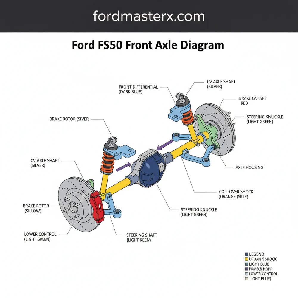
The Ford F-150 front axle diagram serves as a technical roadmap for the truck’s forward propulsion system. At the center of the schematic is the front differential housing, which is bolted to the vehicle’s frame. From this central point, two CV (Constant Velocity) axle shafts extend outward toward the wheel ends. These shafts are often referred to as half-shafts because they represent half of the total axle span from the differential to the hub.
In a standard configuration, the diagram highlights several critical sub-assemblies. The first is the differential itself, which contains the ring and pinion gears, spider gears, and side gears. The diagram will typically show the input flange where the front driveshaft connects. Moving outward, the CV axles are depicted with two distinct joints: the inner joint (usually a tripod style) and the outer joint (a Rzeppa style). These are covered by rubber or thermoplastic boots that hold essential lubrication.
One of the most unique aspects of the F-150 front axle layout is the Integrated Wheel End (IWE) system. This is a vacuum-actuated or electronically controlled clutch assembly located between the CV axle and the wheel hub. In the diagram, you will see the IWE actuator sandwiched between the steering knuckle and the hub bearing. This system is responsible for engaging and disengaging the front wheels from the axle shafts, allowing for improved fuel economy when the truck is in two-wheel-drive mode. Color-coding in a professional blueprint often identifies vacuum lines in blue or black, while structural steel components like the steering knuckle are shaded in grey or silver.
Figure 1: Generalized Front Axle Schematic for Ford F-150 IFS Systems
Reading and interpreting a Ford F-150 front axle diagram requires a systematic approach. To effectively use these schematics for installation or diagnostic purposes, follow these steps:
- ✓ Step 1: Orient the Schematic – Start by identifying the front of the vehicle on the diagram. Usually, the “top” of a blueprint represents the direction of travel. Locate the differential as your central reference point.
- ✓ Step 2: Identify the CV Axle Path – Trace the line from the differential output seals to the wheel hubs. Note where the inner and outer joints are located. If you are replacing an axle, the diagram will show the snap-ring or bolted flange configuration used at the differential side.
- ✓ Step 3: Locate the IWE Components – On F-150 models, the IWE (Integrated Wheel End) system is a common failure point. Find the vacuum hoses on the diagram. They typically lead from a solenoid on the firewall down to the back of the steering knuckle. Understanding this layout is vital for fixing 4WD engagement issues.
- ✓ Step 4: Review Fastener Locations – A quality diagram will label key bolts, such as the large axle nut (hub nut), the three bolts securing the IWE to the knuckle, and the mounting bolts for the differential.
- ✓ Step 5: Verify Torque Specifications – While not always on the diagram itself, the diagram’s component list often cross-references a torque chart. Critical components like the hub nut require precise torque to prevent premature bearing failure.
- ✓ Step 6: Check for Seal Placements – Locate the seals at the differential and the hub. These are shown as thin rings in the assembly layout. Proper orientation of these seals is crucial to prevent gear oil leaks or vacuum loss in the IWE system.
To perform any work based on this diagram, you will need several tools: a heavy-duty floor jack, jack stands, a 1/2-inch drive socket set (including 13mm, 18mm, 21mm, and the specific axle nut size), a torque wrench, and potentially a vacuum pump for testing the IWE system.
Never work under a vehicle supported only by a jack. Always use properly rated jack stands placed on a level surface. When working on the front axle, ensure the vehicle is in “Park” and the rear wheels are chalked to prevent rolling.
The Ford F-150 front axle system is prone to a few specific issues that the diagram can help you diagnose. The most frequent complaint is a “marbles in a can” grinding noise. By looking at the diagram, you can see that this noise originates from the IWE actuator. If the vacuum system fails, the internal gears of the IWE partially engage with the hub, causing the grinding sound. The schematic allows you to trace the vacuum lines from the solenoid to the hub to find cracks or disconnections.
Another common issue is a clicking noise during sharp turns. Referring to the front axle diagram, you will notice the outer CV joints are responsible for allowing the wheels to turn while receiving power. A torn boot on the diagram indicates where grease can escape and dirt can enter, leading to joint failure. If you see grease splattered on the inside of your wheel, the diagram helps you identify which boot needs replacement.
If you are experiencing 4WD issues, check the IWE solenoid located near the brake booster first. It is a much cheaper and easier fix than replacing the actual hub actuators or the CV axles shown in the diagram.
When maintaining your front axle system, quality is paramount. Always opt for OEM (Original Equipment Manufacturer) or high-quality aftermarket components, especially for CV axles and hub bearings. Cheap components often use inferior rubber for the boots, which will crack prematurely under the stress of suspension travel.
Maintenance should include a regular inspection of all rubber components shown on the Ford F-150 front axle diagram. Look for signs of “checking” or small cracks in the CV boots and vacuum lines. If you live in a rust-prone area, apply a light coating of rust-inhibitor to the exposed portions of the axle shafts to prevent structural scaling.
For those looking to save money, performing your own IWE replacement can save hundreds of dollars in labor costs. Using the diagram to understand the stack-up of parts—hub, then IWE, then knuckle—makes the job straightforward. However, if you discover metal shavings inside the front differential or hear a deep howling noise that changes with vehicle speed, these are signs of internal gear wear. In such cases, seeking professional help is recommended, as setting the “backlash” and “preload” on differential gears requires specialized precision tools not found in a standard DIY kit.
Ultimately, the Ford F-150 front axle diagram is more than just a picture; it is a vital tool for ensuring the longevity and capability of your truck. By understanding the system’s structure and layout, you can keep your vehicle off the lift and on the road.
Step-by-Step Guide to Understanding the Ford F150 Front Axle Diagram: Comprehensive Layout Guide
Identify the central differential housing to understand the primary power source.
Locate the CV axles extending from the differential to the wheel hubs.
Understand how the IWE actuators engage the hub with the axle shaft.
Apply the diagram’s layout to inspect vacuum lines for leaks or cracks.
Verify that all mounting bolts and bracketry match the specified configuration.
Complete the inspection by checking for torn boots or leaking differential seals.
Frequently Asked Questions
Where is the front differential located?
The front differential on a Ford F150 is centrally located between the front wheels, mounted to the frame. It sits just behind the front crossmember and connects to the transfer case via the front driveshaft. This component is essential for distributing torque to the individual front half-shafts.
What does this front axle diagram show?
This Ford F150 front axle diagram displays the complete mechanical system responsible for front-wheel power. It highlights the relationship between the differential, CV axles, steering knuckles, and the Integrated Wheel End (IWE) system. Understanding this layout is vital for anyone performing suspension or drivetrain service on their vehicle.
How many connections does the IWE system have?
The IWE system typically features two primary connections: a vacuum line and a mechanical splined interface. The vacuum system controls the engagement of the hub to the axle shaft, while the splined configuration ensures a solid physical link when 4WD is activated by the driver inside the cabin.
What are the symptoms of a bad front axle?
Common symptoms of front axle issues include clicking sounds while turning, which often indicate worn CV joints. If you hear grinding, it might suggest a failure within the IWE system or the differential itself. Any vibrations felt through the floorboards or steering wheel during 4WD engagement are also red flags.
Can I replace a CV axle myself?
Replacing a CV axle is a manageable DIY task for those with intermediate mechanical skills and the right tools. It involves removing the wheel, brake assembly, and disconnecting the lower ball joint or upper control arm. Using a detailed diagram ensures you reinstall all spacers and fasteners in the correct order.
What tools do I need for front axle work?
You will typically need a heavy-duty jack and stands, a socket set including a large 35mm or 36mm axle nut socket, a torque wrench, and a pry bar. Additionally, having a vacuum pump can be extremely helpful for testing the IWE system’s integrity during the assembly process.


