The Definitive Engineering & Fitment Guide: Ford F-150 Wheel Bolt Patterns (1975–Present)
The Ford F-150 stands as a monolithic figure in the global automotive landscape, representing not just a sales leader but a continuous case study in the evolution of light-duty truck engineering. While marketing literature often highlights horsepower figures, towing capacities, and interior amenities, the fundamental interface between the vehicle’s chassis and the road surface—the wheel assembly—remains the most critical mechanical junction in terms of safety and dynamic performance.
This report serves as an exhaustive technical analysis of the F-150’s wheel fitment specifications, covering the bolt pattern (Pitch Circle Diameter), fastener geometry, hub architecture, and torque requirements from the mid-1970s through the electric vehicle era of today.
The evolution of the F-150’s wheel specifications is not arbitrary. It mirrors the broader trajectory of automotive engineering, transitioning from the loose tolerances and Imperial measurements of the agrarian work truck to the high-precision, metric-standardized, and structurally optimized systems required by modern luxury and performance vehicles.
For the automotive technician, the aftermarket engineer, or the dedicated enthusiast, understanding these transitions is paramount. A misstep in identifying a thread pitch or a bolt circle—often a difference of mere millimeters—can lead to catastrophic mechanical failure, wheel separation, or compromised structural integrity.
This analysis dissects the F-150’s history into distinct engineering eras, analyzing the technical rationale behind the shift from 5-lug to 6-lug configurations, the anomaly of the 7-lug Heavy Duty Payload Package (HDPP), and the nuances of fastener metallurgy that distinguish the 12mm, 14mm coarse, and 14mm fine thread epochs. Furthermore, we examine the physics of clamping force, the debate surrounding hub-centric versus lug-centric fitment, and the specific requirements of the F-150 Lightning electric vehicle.
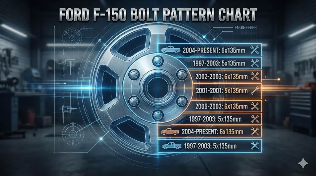
Ford F-150 Bolt Pattern Chart
The Ultimate Guide to Fitment, Thread Pitch & Torque Specs
Why This Matters
Fitting the wrong wheels isn’t just an aesthetic issue—it’s a safety hazard. While the Ford F-150 has been the best-selling truck for decades, Ford hasn’t kept the wheel specs constant. From the 5-lug days of the 90s to the modern 6-lug heavy-duty setup, knowing your exact Bolt Pattern and Thread Pitch is critical to prevent wheel vibration, stud failure, or falling wheels.
Historical Evolution
A timeline of how the F-150 wheel hub has changed over the last 30 years.
1996 & Older (OBS)
Pattern: 5 x 139.7mm (5×5.5″)
The classic “old body style” Ford pattern used for decades. Also found on older Broncos.
1997 – 2003 (10th Gen)
Pattern: 5 x 135mm
The “Jellybean” era introduced a metric pattern unique to this
generation and the Expedition of the same era.
Warning:
Early models (97-99) used 12mm studs; later (00-03) used 14mm
studs.
2004 – 2014 (11th & 12th Gen)
Pattern: 6 x 135mm
The switch to a 6-lug hub for increased payload capacity. This pattern (6×135) is physically the same as modern trucks, but the lug nuts are different.
2015 – Present (Aluminum Body)
Pattern: 6 x 135mm (New Thread)
While the bolt pattern remained 6×135, Ford changed the thread pitch from 2.0 to 1.5. Old lug nuts will NOT fit new trucks.
The Thread Pitch Trap
The most common mistake owners make is assuming all “6-lug Ford wheels” are interchangeable. While the holes line up, the lug nuts do not.
M14 x 2.0
Coarse Thread
Used on 11th and 12th Gen trucks. These lug nuts are known for being susceptible to swelling if the chrome cap fails.
M14 x 1.5
Fine Thread
Used on aluminum body trucks (13th & 14th Gen). Finer threads provide higher clamping force resistance to vibration.
Torque Specifications
Under-torquing leads to loose wheels; over-torquing warps rotors. See how the requirements increased as trucks got more capable.
Tightening Sequence Visualizer
Always tighten lug nuts in a star pattern to ensure even seating of the wheel against the hub. Follow the numbers below (1 → 6) for the correct order.
6-Lug Pattern (Modern)
5-Lug Pattern (Legacy)
The “Heavy Duty” Anomaly (7-Lug)
Between 2004 and 2014, Ford produced a special “Heavy Duty Payload Package” (Option Code 627). These unique trucks feature a 7 x 150mm bolt pattern.
© 2026 FordMasterX Infographics. Data sourced from manufacturer owner manuals.
Theoretical Framework: The Physics of the Bolted Joint
To fully appreciate the specifications detailed later in this report, one must first understand the mechanical principles governing wheel attachment. A wheel is not held onto a vehicle primarily by the shear strength of the studs, but rather by the friction force generated between the wheel’s mounting face and the vehicle’s hub.
Clamping Force and Friction
The lug nut, when tightened, acts as a tensioning device. It stretches the wheel stud, which acts like a stiff spring. This tension creates a compressive force, known as the clamp load, pressing the wheel against the hub. The friction capacity of this interface is defined by the formula:
$F_f = \mu \times F_n$
Where:
- $F_f$ is the Friction Force (resistance to slip).
- $\mu$ is the coefficient of friction between the mating surfaces.
- $F_n$ is the Normal Force (Clamp Load) generated by the torque.
The F-150’s transition from 100 ft-lbs of torque in the 1990s to 150 ft-lbs (and potentially 162 ft-lbs for the Lightning) in the modern era is a direct response to increasing vehicle mass, tire diameter, and tractive capability.1 Heavier trucks with more powerful engines generate significantly higher shear loads during acceleration, braking, and cornering. Higher torque specifications are required to generate sufficient clamp load to prevent the wheel from slipping on the hub face. If the wheel slips, the load transfers directly to the studs in shear—a loading condition for which they are not primarily designed—often resulting in stud fatigue and fracture.
Hub-Centricity vs. Lug-Centricity
The F-150 utilizes a hub-centric design philosophy. In this system, the vehicle’s weight is supported by the hub pilot (the protruding lip of the hub) fitting precisely into the wheel’s center bore.
- Hub-Centric: The spigot/pilot bears the vertical load (shear load from vehicle weight and impacts). The lug nuts serve primarily to provide lateral clamping force. This isolates the studs from vertical bending moments.
- Lug-Centric: Common in universal aftermarket wheels, this relies on the conical seat of the lug nuts to center the wheel and support the vehicle’s weight. While functional, this places the studs under combined shear, bending, and tensile loads, significantly reducing the safety factor.
For the F-150, particularly modern variants with aluminum bodies and highly tuned suspensions, maintaining hub-centricity is critical. The hub bore diameter—108mm for classic trucks and 87.1mm for modern trucks—is a non-negotiable dimension for ensuring a vibration-free ride and structural safety.7
The Imperial Era: 1st through 9th Generation (1975–1996)
The formative years of the F-150 (following the rebranding from F-100) were characterized by component interchangeability and the dominance of the SAE (Society of Automotive Engineers) Imperial measurement system. During this period, the F-150 shared its wheel architecture with the Ford Bronco, the E-150 Econoline van, and even competitive vehicles like the Dodge Ram 1500 and Jeep CJ series, creating a ubiquitous standard in the American truck market.
Bolt Pattern Analysis: 5×5.5″ (139.7mm)
From 1975 through the end of the 1996 model year, every F-150 utilized the 5 on 5.5 inch bolt pattern.1
- Geometry: This pattern consists of 5 studs arranged on a circle with a diameter of 5.5 inches (mathematically equivalent to 139.7mm).
- Measurement Technique: Measuring an odd-numbered bolt pattern (5-lug) is notoriously difficult for the layperson because there is no stud directly opposite another. The correct method involves measuring from the back edge of one hole to the center of the second hole (skipping one stud). Alternatively, a specialized bolt pattern gauge is recommended. A direct center-to-center measurement of adjacent studs does not yield the PCD.9
- Engineering Context: The 5.5-inch circle is relatively large for a 5-lug application (compare to the 4.5-inch pattern on Ford passenger cars like the Mustang). This wide diameter was necessary to clear the large manual locking hubs found on the Dana 44 front axles of 4WD models.
Hub Architecture and Bore Diameter
The definitive feature of this era is the massive center bore. The standard hub bore for 1975–1996 F-150s is 108mm (approx. 4.25 inches).
- Implication: This large bore is the primary limiting factor in wheel interchangeability. Modern F-150 wheels (2004–Present) have a smaller 87.1mm bore. Therefore, it is physically impossible to mount a stock 2020 F-150 wheel on a 1990 F-150 because the wheel simply will not fit over the hub.7
- Aftermarket: Wheels designed for this era typically feature a “push-through” center cap to accommodate the protruding 4WD locking hubs.
Fastener Specifications: The 1/2-20 Standard
During this era, Ford utilized Imperial fasteners.
- Thread Size: 1/2-20 UNF. This indicates a stud diameter of 1/2 inch with 20 threads per inch.13
- Lug Nut Type: Standard conical seat (60-degree taper).
- Torque Specification: The recommended torque for this generation is generally 100 ft-lbs.1 This lower torque figure (compared to modern trucks) reflects the lower tensile strength of the 1/2-inch studs and the steel wheel composition common to the era.
Table 3.1: 1975–1996 F-150 Wheel Specifications
| Feature | Specification | Notes |
| Bolt Pattern | 5 x 5.5″ (5 x 139.7mm) | Classic “Large Ford” pattern. |
| Lug Count | 5 | Odd number requires specific measurement technique. |
| Stud Size | 1/2-inch x 20 UNF | Imperial fine thread. |
| Center Bore | 108mm | Large bore to clear 4WD locking hubs. |
| Torque Spec | 100 ft-lbs | |
| Fitment | Lug-Centric (often) | Steel wheels relied heavily on lug centering. |
The Transitional Era: 10th Generation (1997–2003)
The 1997 model year marked the most significant paradigm shift in F-Series history. Ford introduced the “PN-96” platform, characterized by its aerodynamic styling and a completely new chassis architecture. This generation is infamous among technicians for its confusing transition from Imperial to Metric standards and the “split year” changes in fastener sizes.
The Metric Revolution: 5x135mm
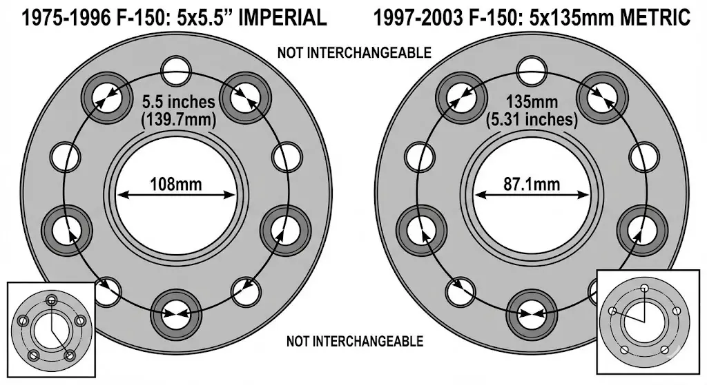
Ford abandoned the decades-old 5×5.5″ pattern in favor of the metric 5x135mm pattern.
- Why the Change?: The new Independent Front Suspension (IFS) and lighter chassis components were designed with tighter tolerances. The 135mm circle is slightly smaller (approx. 5.3 inches) than the previous 5.5-inch circle.
- Interchangeability Trap: Visually, the 5x135mm pattern looks nearly identical to the 5×5.5″ pattern. However, they are not compatible. Attempting to force a 5×5.5″ wheel onto a 5x135mm hub will bend the studs and ruin the wheel.
- Hub Bore Reduction: The center bore was reduced to 87.1mm, a standard that remains in use today.7 This reduction reflected the move away from large manual locking hubs to vacuum-actuated Integrated Wheel Ends (IWEs).
The Stud Diameter Crisis: 12mm vs. 14mm
The most critical maintenance hazard for the 10th Generation F-150 is the mid-cycle change in stud diameter.
- 1997–1999 (Early): Most trucks were equipped with 12mm x 1.75 studs. The torque spec for these is 100 ft-lbs.3
- 2000–2003 (Late): Ford began transitioning to thicker 14mm x 2.0 studs to increase payload safety margins. The torque spec for these is 150 ft-lbs.8
- The Danger:
- Scenario A: A technician assumes a 2001 truck has 12mm studs and torques them to 100 ft-lbs. Result: Insufficient clamp load, leading to wheel vibration or separation.
- Scenario B: A technician assumes a 1998 truck has 14mm studs and torques them to 150 ft-lbs. Result: The 12mm studs are stretched beyond their yield point (plastic deformation), likely snapping immediately or failing on the road.
- Scenario C: Using 12mm lug nuts on 14mm studs (impossible—won’t fit).
- Scenario D: Using 14mm lug nuts on 12mm studs. Result: The nut will slide over the threads without engaging, stripping them instantly if tightened with an impact gun.
Identification Strategy: It is impossible to reliably determine the stud size by VIN alone during the transition years (1999-2001). Physical verification using a thread pitch gauge or a test nut is mandatory before servicing these vehicles.
The “Heritage” Anomaly (2004)
The 2004 model year introduces a unique naming conflict. Ford introduced the new 11th Generation truck (New Body Style) in 2004 but continued to sell the 10th Generation body as the F-150 Heritage.16
- 2004 F-150 Heritage: Retains the 5x135mm pattern and 10th-gen specs.
- 2004 F-150 (New Style): Adopts the 6x135mm pattern.
- Service Note: When ordering wheels or rotors for a “2004 F-150,” one must specify “Heritage” or “New Body Style.”
Table 4.1: 1997–2003 F-150 Wheel Specifications
| Feature | Specification | Notes |
| Bolt Pattern | 5 x 135mm | Unique to this generation and Expedition. |
| Lug Count | 5 | Metric pattern. |
| Stud Size (Early) | 12mm x 1.75 | 1997–1999 (approx). Torque: 100 ft-lbs. |
| Stud Size (Late) | 14mm x 2.0 | 2000–2003 (approx). Torque: 150 ft-lbs. |
| Center Bore | 87.1mm | Modern standard established here. |
| Fitment | Hub-Centric | Critical for preventing vibration. |
The Heavy Duty Payload Package (HDPP): The 7-Lug Oddity
Within the taxonomy of F-150s, there exists a rare subspecies designed to bridge the gap between the half-ton F-150 and the three-quarter-ton F-250. These vehicles, variously marketed as the “7700 Series” (referencing a 7,700 lb GVWR) or the “Heavy Duty Payload Package” (HDPP), feature a bolt pattern unique in the entire light-truck industry.
The 7x150mm Configuration
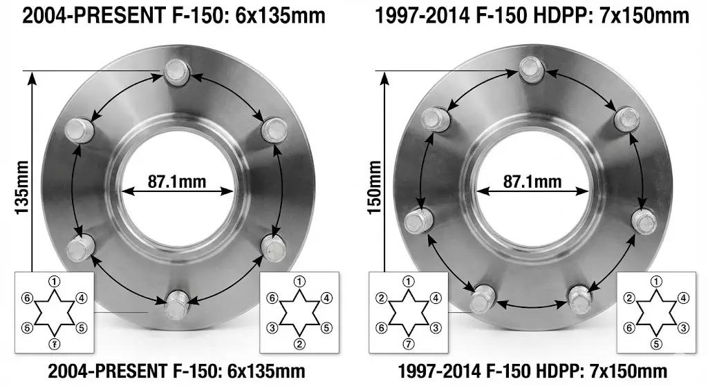
From roughly 1997 through 2014, select heavy-duty F-150s utilized a 7-lug wheel pattern on a 150mm bolt circle ($7 \times 150\text{mm}$).
- Engineering Rationale: The 7-lug design provided additional clamping force and load distribution for the significantly higher axle ratings (often using a 10.25-inch semi-float rear axle). The 150mm circle diameter is extremely wide, further stabilizing the wheel under heavy lateral loads.
- Production Years:
- 1997–1999: Badged as “F-250 Light Duty” (using the F-150 body).
- 2000–2003: Badged as F-150 “7700 Payload Group.”
- 2004–2014: Continued as an option on XL and XLT trims with the heavy-duty payload package.2
- Demise: The 7-lug pattern was discontinued after the 2014 model year. The 2015+ HDPP trucks reverted to a reinforced version of the standard 6-lug pattern.17
Sourcing and Compatibility
Owners of 7-lug F-150s face significant challenges in the aftermarket.
- Wheel Availability: Almost zero off-the-shelf aftermarket wheels exist for the 7x150mm pattern. Owners typically must rely on OEM steel wheels or order custom-drilled forged wheels.18
- Identification: These trucks can be identified by counting the lugs, checking the door jamb sticker for the “Heavy Duty Payload” designation, or noting the 7-lug specific axle hub covers.
The Modern Frame Era: 11th & 12th Generation (2004–2014)
With the introduction of the 11th Generation in 2004, Ford moved to a fully boxed frame and significantly increased the F-150’s structural rigidity. This era standardized the wheel architecture that would define the platform for the next two decades.
Standardization of 6x135mm
The defining characteristic of the modern F-150 wheel is the 6x135mm bolt pattern.3
- Structural Logic: The move from 5 to 6 lugs was necessitated by the “arms race” of towing capacities. As half-ton trucks began rated to tow 9,000, 10,000, and eventually 11,000 lbs, the clamping load provided by 5 lugs was deemed insufficient for the safety margins Ford required.
- Geometry: 6 studs arranged on a 135mm diameter circle.
- Measurement: Measuring a 6-lug pattern is simpler than a 5-lug. One measures from the center of one hole directly to the center of the opposite hole. If the distance is approximately 5.3 inches ($135\text{mm}$), it confirms the Ford pattern.9 Note that this is distinct from the Chevy/Toyota standard of 6×139.7mm ($6 \times 5.5″$). The two are close, but not interchangeable.
Fastener Specifications: 14mm x 2.0 Coarse Thread
For the entirety of the 2004–2014 production run, Ford utilized 14mm x 2.0 studs.
- Coarse Pitch: The 2.0mm thread pitch (distance between threads) is relatively coarse. This design choice favors durability and ease of assembly. Coarse threads are less likely to cross-thread when starting nuts by hand and are more tolerant of dirt and debris—a common scenario for work trucks.
- Torque Specification: The standard torque for this era is 150 ft-lbs.
- Lug Nut Design: These trucks typically used a “capped” lug nut. A stainless steel cap was crimped over a steel core.
- The Swelling Issue: A notorious issue with 2004–2014 F-150s is the swelling of these OEM lug nuts. Moisture enters between the cap and the core, causing corrosion that expands the cap. A standard 21mm socket will no longer fit, leaving owners stranded with a flat tire they cannot remove. It is widely recommended to replace these with solid one-piece aftermarket nuts.
The SVT Raptor (Gen 1: 2010–2014)
The first-generation SVT Raptor utilized the same 6x135mm bolt pattern and 14×2.0 studs as the standard F-150.
- Wheel Specifics: While the bolt pattern is identical, Raptor wheels feature a distinct offset (typically +34mm) compared to the standard F-150 (+44mm). This lower offset pushes the wheel outward to accommodate the wider suspension track and 35-inch tires.
- Beadlocks: The Raptor introduced optional beadlock-capable wheels. These allow the tire bead to be clamped physically to the wheel, permitting extremely low tire pressures for sand driving without the tire de-beading.
The Aluminum Era: 13th & 14th Generation (2015–Present)
The 2015 model year marked another revolutionary step: the switch to an all-aluminum body. While this saved weight, the wheel specifications underwent a subtle but critical change that continues to baffle owners and technicians.
The Thread Pitch Change: 14mm x 1.5 Fine Thread
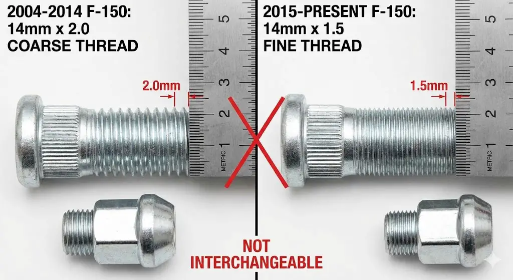
Starting in 2015, Ford changed the wheel stud specification from $14\times2.0$ to $14\times1.5$.3
- Engineering Rationale: Fine threads ($1.5\text{mm}$ pitch) offer several mechanical advantages over coarse threads:
- Higher Clamping Force: For the same input torque (150 ft-lbs), a fine thread generates higher axial tension (clamp load) due to the shallower incline of the thread helix.
- Vibration Resistance: The shallower angle creates more friction within the thread interface, making the nut less likely to loosen under vibration.
- Shear Area: Fine threads have a larger minor diameter, slightly increasing the tensile strength of the stud.
- The Compatibility Hazard:
- Lug Nuts: A lug nut from a 2014 F-150 ($14\times2.0$) will not thread onto a 2015+ stud. If forced, it will destroy the threads.
- Wheels: The wheels themselves are interchangeable between 2004–2014 and 2015+ trucks (same PCD, same center bore). However, one must use the lug nuts that match the truck, not the nuts that came with the wheels if they are from a different generation.23
Fitment Continuity
Aside from the thread pitch, the core geometry remained stable:
- Bolt Pattern: 6x135mm.
- Center Bore: 87.1mm.
- Torque Spec: 150 ft-lbs.
14th Generation (2021–Present)
The 2021 update introduced new features like Onboard Scales and Smart Hitch, which use suspension height sensors to estimate payload.
- Wheel Implications: While the bolt pattern remains 6x135mm, the calibration of these electronic systems can be sensitive to changes in unsprung mass (heavier aftermarket wheels) or significant changes in tire diameter, which alter the effective leverage on the suspension components.
- Raptor (Gen 3): The 2021+ Raptor and Raptor R continue with the 6x135mm pattern but offer a “37 Performance Package.” These wheels are specifically engineered to handle the rotational inertia of 37-inch tires and feature a specific +30mm offset.
The Electric Frontier: F-150 Lightning (2022–Present)
The electrification of the F-Series introduces the F-150 Lightning. With a curb weight exceeding 6,500 lbs and instantaneous electric torque, the demands on the wheel assembly are higher than ever.
Shared Architecture, Specific Execution
The Lightning shares the 6x135mm bolt pattern and 14×1.5 thread pitch with the standard ICE F-150.
- Interchangeability: Technically, standard F-150 wheels will bolt onto a Lightning. However, Lightning-specific wheels are aerodynamically optimized to reduce drag. Installing standard “open” spoke wheels can reduce the EV’s range by 5-10% due to increased turbulence.
- Load Rating: Lightning wheels are reinforced to handle the extreme weight of the battery pack. Using lightweight aftermarket wheels designed for a standard F-150 on a Lightning is dangerous, as they may not meet the load rating requirements (approx. 2,000+ lbs per wheel).
The Torque Specification Debate
A point of contention exists regarding the Lightning’s torque spec.
- Official Manual: The 2023/2024 Owner’s Manuals typically list 150 ft-lbs (204 Nm), aligning with the gas trucks.
- Specialized References: Some aftermarket EV specialists and early service literature reference a higher spec of 162 ft-lbs (219 Nm).
- Analysis: The higher 162 ft-lbs figure likely stems from Ford’s internal durability testing for the heavier EV platform. Given the massive torque applied to the wheels by the electric motors (775 lb-ft total system torque), the risk of fastener loosening is higher.
- Recommendation: Owners should adhere strictly to the manual provided with their specific VIN. However, frequent torque checks (every 1,000 miles) are prudent for EVs due to the aggressive regenerative braking forces that cycle loads on the studs in reverse.
9. Comprehensive Data Tables
The following tables synthesize the data into actionable references.
Table 1: Master F-150 Bolt Pattern & Fastener Chart (1975–2025)
| Generation | Production Years | Bolt Pattern | Lug Count | Thread Size | Center Bore | Torque Spec | Notes |
| 1st – 9th | 1975 – 1996 | 5 x 5.5″ (139.7mm) | 5 | 1/2-20 UNF | 108mm | 100 ft-lbs | Imperial Era |
| 10th | 1997 – 1999 | 5 x 135mm | 5 | 12mm x 1.75 | 87.1mm | 100 ft-lbs | Early Metric |
| 10th | 2000 – 2003 | 5 x 135mm | 5 | 14mm x 2.0 | 87.1mm | 150 ft-lbs | Verify Stud Size! |
| HDPP (7700) | 2000 – 2003 | 7 x 150mm | 7 | 14mm x 2.0 | 87.1mm | 150 ft-lbs | 7-Lug Oddity |
| Heritage | 2004 | 5 x 135mm | 5 | 14mm x 2.0 | 87.1mm | 150 ft-lbs | Old Body Style |
| 11th | 2004 – 2008 | 6 x 135mm | 6 | 14mm x 2.0 | 87.1mm | 150 ft-lbs | New Body, Coarse Thread |
| 12th | 2009 – 2014 | 6 x 135mm | 6 | 14mm x 2.0 | 87.1mm | 150 ft-lbs | Raptor Gen 1 |
| HDPP | 2004 – 2014 | 7 x 150mm | 7 | 14mm x 2.0 | 87.1mm | 150 ft-lbs | Final 7-Lug Era |
| 13th | 2015 – 2020 | 6 x 135mm | 6 | 14mm x 1.5 | 87.1mm | 150 ft-lbs | Fine Thread Switch |
| 14th | 2021 – Present | 6 x 135mm | 6 | 14mm x 1.5 | 87.1mm | 150 ft-lbs | Smart Hitch tech |
| Lightning | 2022 – Present | 6 x 135mm | 6 | 14mm x 1.5 | 87.1mm | 150 ft-lbs* | *Some sources cite 162 ft-lbs |
Table 2: Hub Bore Compatibility Matrix
| Origin Truck (Wheel Source) | Destination Truck (Installation) | Fitment Status | Required Action |
| 1996 (108mm Hub) | 2020 (87.1mm Hub) | Incompatible | Bolt pattern mismatch (5-lug vs 6-lug). |
| 2020 (87.1mm Hub) | 1996 (108mm Hub) | Incompatible | Wheel bore is too small for the hub. |
| 2004-2014 (87.1mm Hub) | 2015+ (87.1mm Hub) | Compatible | MUST use 2015+ lug nuts (14×1.5). |
| 2015+ (87.1mm Hub) | 2004-2014 (87.1mm Hub) | Compatible | MUST use 2004-2014 lug nuts (14×2.0). |
| Aftermarket (106mm Bore) | 2004+ (87.1mm Hub) | Compatible | Requires Hub-Centric Rings (106mm -> 87.1mm). |
Technical Deep Dive: Offset, Backspacing, and Scrub Radius
While the bolt pattern determines if a wheel can bolt on, the offset determines where the wheel sits in relation to the suspension and bodywork.
Offset vs. Backspacing
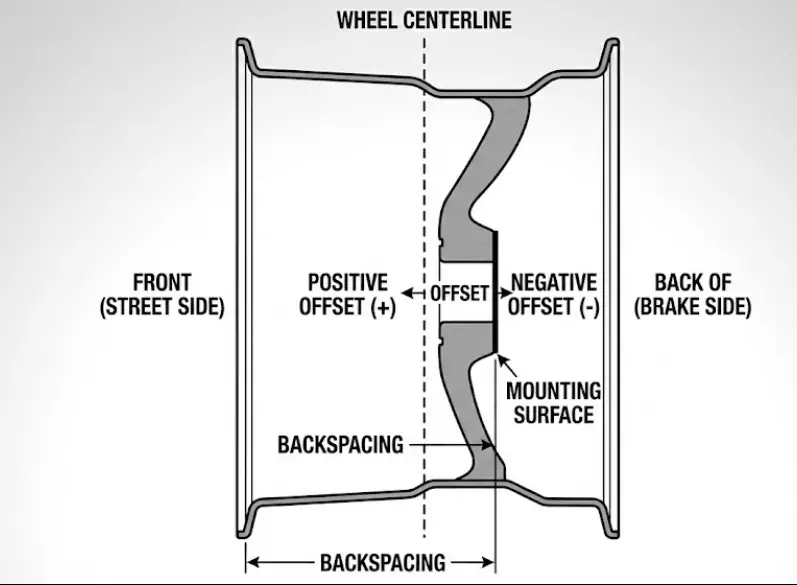
These two terms describe the same attribute but from different reference points.
- Offset (mm): The distance from the wheel’s centerline to the mounting surface.
- Positive (+): Mounting surface is toward the street side (wheel tucks in). F-150 stock is typically +44mm.
- Negative (-): Mounting surface is toward the brake side (wheel sticks out). Deep dish wheels are negative offset.
- Backspacing (inches): The distance from the back edge of the wheel to the mounting surface.
- Relationship: As Positive Offset decreases (moves toward zero or negative), Backspacing decreases.
Scrub Radius Mechanics
The F-150’s suspension geometry is designed around a specific scrub radius—the distance between the center of the tire contact patch and the point where the steering axis intersects the road.
- Stock Scrub: Usually slightly negative or zero to provide straight-line stability and braking control.
- Aftermarket Effect: Installing wheels with aggressive negative offset (e.g., -12mm) pushes the wheels out, drastically increasing the scrub radius (positive scrub).
- Consequences:
- Steering Feedback: The steering wheel will “fight” the driver over bumps (bump steer).
- Component Wear: The wheel acts as a longer lever arm against the hub bearing and ball joints, accelerating wear by up to 50%.
- Safety: Under hard braking on split-traction surfaces (one wheel on ice, one on pavement), a large positive scrub radius can cause the steering wheel to rip out of the driver’s hands.
Aftermarket Modification: Spacers and Adapters
Wheel spacers are a controversial topic in truck engineering. They are often used to achieve a wider stance or clear larger tires, but they introduce significant failure points if misunderstood.
Slip-On vs. Bolt-On
- Slip-On Spacers: Thin discs (usually <5mm) that slide over the existing studs.
- Risk: They reduce the thread engagement of the lug nut. A lug nut requires engagement equal to the diameter of the stud (e.g., 14mm of thread engagement). A 5mm spacer removes 5mm of engagement, potentially leaving insufficient threads to hold the torque.
- Bolt-On Adapters: Thick spacers (usually >1 inch) that bolt to the hub and have their own studs for the wheel.
- Requirement: These must be hub-centric. If an adapter is lug-centric, the entire weight of the truck hangs on the adapter studs, leading to vibration and shear failure.
- Torque: The adapter must be torqued to the hub (150 ft-lbs), and then the wheel torqued to the adapter. Crucial: The inner nuts holding the adapter must be checked periodically, which requires removing the wheel.
Material Science
High-quality adapters are machined from 6061-T6 or 7075-T6 aluminum. Cheap, unbranded spacers are often cast aluminum, which contains air pockets and lacks the tensile strength to resist the F-150’s clamping loads. Using cast spacers on a heavy truck is a severe safety hazard.
Practical Guide: Identification and Measurement
For the DIY mechanic or buyer inspecting a used truck or set of wheels, verifying these specs physically is essential.
Measuring the Bolt Pattern
- 6-Lug (Even Number): Measure from the center of one stud hole directly across to the center of the opposite stud hole.
- If it measures 135mm (5.31″), it is a Ford F-150.
- If it measures 139.7mm (5.5″), it is a Chevy/Toyota/Ram pattern.
- Visual Tip: The difference is only 4.7mm. If the tape measure looks “just a hair over 5 and a quarter,” it’s likely Ford. If it looks “exactly 5 and a half,” it’s Chevy.
- 5-Lug (Odd Number): Do not measure center-to-center of adjacent holes. Measure from the back edge of one hole to the center of the second hole (skip one).
- Reading ~5.5″ = 1975-1996 Ford.
- Reading ~5.3″ = 1997-2003 Ford.
Lug Nut Torque Sequence
Proper torque sequence ensures the wheel seats flat against the hub. Uneven tightening warps the brake rotor, causing pulsation.
- Star Pattern:
- 5-Lug: 1-3-5-2-4.
- 6-Lug: 1-4-2-5-3-6.
- 7-Lug: 1-4-7-3-6-2-5.
- Process:
- Step 1: Hand tighten all nuts.
- Step 2: Snug to ~50 ft-lbs in star pattern.
- Step 3: Torque to full spec (150 ft-lbs) in star pattern.
Conclusion
The Ford F-150’s wheel architecture is a narrative of continuous improvement, driven by the demands for higher payload, greater safety, and improved manufacturing precision. From the interchangeability of the Imperial 5×5.5 era to the high-stakes specificity of the modern metric era, the bolt pattern serves as a key indicator of the truck’s underlying engineering generation.
For the modern owner, the lessons are clear:
- Respect the Thread Pitch: The 2015 split between $14\times2.0$ and $14\times1.5$ is the most common cause of component damage.
- Verify Torque: The 150 ft-lbs standard is non-negotiable for modern trucks.
- Maintain Hub-Centricity: Whether through OEM wheels or aftermarket rings, the hub connection is the foundation of ride quality and safety.
By adhering to these technical specifications, operators ensure the longevity and safety of the most popular vehicle in North American history.


