Ford Explorer Sport Trac Fuse Box Diagram: Diagnosis Guide
The 2004 Ford Explorer Sport Trac features two main fuse centers: the passenger compartment fuse panel located under the dashboard on the driver’s side and the power distribution box found in the engine compartment. These diagrams provide the specific amperage and function for every circuit, including the ECU and OBD-II port.
📌 Key Takeaways
- Identify the two primary fuse box locations in the cabin and engine bay
- Locate the specific fuse for the OBD-II port and ECU power supply
- Always match the replacement fuse amperage to the original diagram specifications
- Use the diagram to troubleshoot a check engine light caused by circuit failure
- Consult the diagram whenever electronic accessories or lights fail to operate
Finding the correct 2004 ford explorer sport trac fuse box diagram is the first step in resolving frustrating electrical glitches, from a silent radio to a non-responsive starter. This comprehensive guide serves as your primary resource for identifying every fuse, relay, and diode within your vehicle’s electrical architecture. By understanding the layout of both the passenger compartment panel and the power distribution box, you can effectively troubleshoot issues, reset diagnostic codes, and ensure your vehicle’s critical systems—like the ECU and fuel pump—are receiving the power they need to function safely and efficiently on the road.
The 2004 Ford Explorer Sport Trac utilizes two distinct fuse locations: the Passenger Compartment Fuse Panel located on the driver’s side of the instrument panel, and the Power Distribution Box situated in the engine compartment near the battery. Always check both locations when troubleshooting complex electrical failures.
Understanding the 2004 Ford Explorer Sport Trac Fuse Box Layout
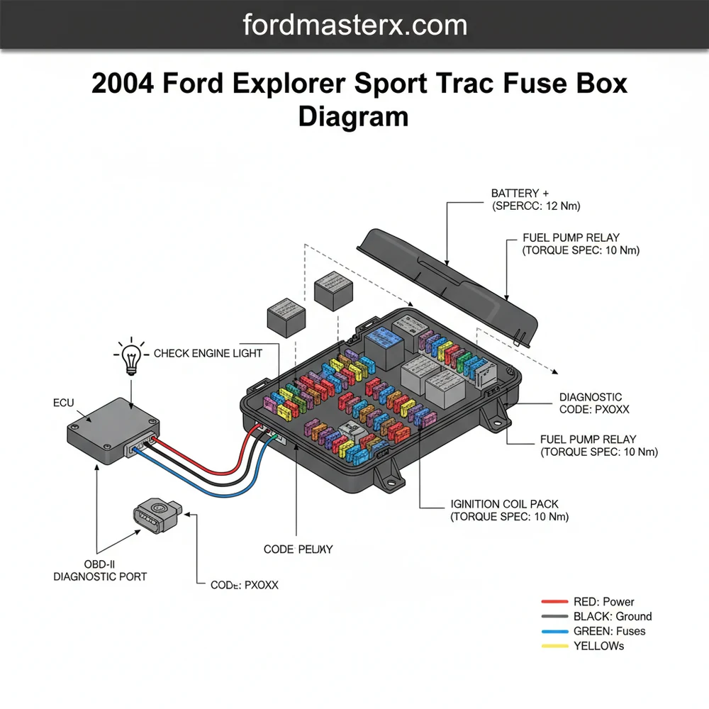
The electrical system of the 2004 Ford Explorer Sport Trac is divided into high-current and low-current circuits. The Power Distribution Box, located under the hood, houses high-amperage “Maxi” fuses and relays that protect heavy-duty components such as the starter motor, blower motor, and the anti-lock brake system (ABS). These components require significant current to operate, and the larger fuses provide a robust fail-safe. In contrast, the Passenger Compartment Fuse Panel utilizes “Mini” fuses, which are designed for precision protection of sensitive electronics like the instrument cluster, interior lighting, and the OBD-II diagnostic port.
The diagram for these boxes is typically organized in a grid format. Each slot is numbered, corresponding to a specific circuit described in your owner’s manual. On the interior panel, you will find fuses ranging from 5A to 30A. On the engine bay distribution box, you will see larger cartridge fuses (20A to 60A) and rectangular relays. The relays act as electrically operated switches, allowing a low-current signal from your dashboard switches to trigger a high-current flow to the actual component, such as the horn or the fuel pump.
[DIAGRAM_PLACEHOLDER: A detailed visual map showing the 2004 Ford Explorer Sport Trac Fuse Box locations. The visual should highlight the Passenger Compartment Panel on the left side of the dashboard and the Power Distribution Box near the battery in the engine bay, with specific callouts for the ECU relay and OBD-II fuse.]
A critical element of the diagram is the inclusion of the PCM (Powertrain Control Module) or ECU fuse. If this fuse blows, the engine will crank but fail to start, and your OBD-II scanner will likely be unable to establish a connection with the vehicle. Understanding this relationship is vital for any DIYer attempting to clear a check engine light or investigate a mysterious diagnostic code.
Step-by-Step Guide to Reading and Replacing Fuses

Navigating the 2004 ford explorer sport trac fuse box diagram requires a systematic approach. Follow these steps to safely identify and resolve electrical issues without damaging sensitive vehicle electronics.
- Locate the Desired Panel: For interior issues like power windows or the radio, open the driver’s door and look at the side of the dashboard. There is a removable plastic cover. For engine-related issues, pop the hood and locate the black rectangular box near the battery on the driver’s side.
- Reference the Diagram: Use the diagram printed on the inside of the fuse box cover or the one provided in this guide. Cross-reference the fuse number with the function list (e.g., Fuse #24 might control the cigarette lighter).
- Select the Right Tools: You should use a dedicated fuse puller tool, often located inside the fuse box or available at any auto parts store. Avoid using metal pliers unless the battery is disconnected, as you risk shorting out adjacent circuits.
- Perform a Visual Inspection: Pull the suspected fuse and hold it up to a light source. Look at the metal wire inside the plastic housing. If the “U” shaped wire is broken or if the plastic is charred, the fuse is blown and must be replaced.
- Test with a Multimeter (Optional): For a more accurate diagnosis, set a multimeter to the Continuity or Ohms setting. Touch the probes to the two small metal contact points on the top of the fuse while it is still installed. A “beep” indicates the fuse is good.
- Verify Amperage: Before inserting a new fuse, check the color and the number printed on top. Fuses are color-coded: Blue is 15A, Yellow is 20A, Green is 30A, etc. Never replace a fuse with one of a higher amperage rating, as this can lead to a vehicle fire.
- Re-test the Component: Once the new fuse is in place, turn the ignition to the “On” position and check the component. If the fuse blows again immediately, you have a short circuit that requires further investigation.
Never use a piece of foil, a paperclip, or a higher-rated fuse to bypass a blown circuit. Fuses are designed to be the “weakest link” in the chain. If you force the circuit to carry more current than intended, the heat will melt the wiring harness, potentially leading to a catastrophic fire or permanent damage to the ECU.
During this process, pay close attention to the OBD-II fuse (usually found in the interior panel). This fuse powers the diagnostic link connector. If your check engine light is on but your scanner won’t turn on when plugged in, this specific fuse is almost certainly the culprit.
Common Issues & Troubleshooting Electrical Failures

The 2004 Explorer Sport Trac is known for a few specific electrical quirks that can be solved using the fuse box diagram. One frequent problem is the “No Start” condition where the dashboard lights up, but the engine won’t turn over. Often, this is not a failed starter but a blown “Starter Relay” or “Fuel Pump Relay” in the Power Distribution Box.
Another common issue involves the check engine light and a failure to pass emissions. If you receive a diagnostic code related to the oxygen sensors or the EVAP system, don’t immediately replace the sensors. Check the fuses in the engine compartment first. Several engine sensors share a common power source; if that fuse is blown, it will trigger multiple codes simultaneously, misleading you into expensive and unnecessary repairs.
- ✓ Intermittent Power: If windows or locks work only sometimes, check for loose relays in the interior panel.
- ✓ Radio/Display Blackout: Check Fuse #29 (20A) in the passenger compartment.
- ✓ Trailer Lights Failure: The Sport Trac has dedicated fuses for trailer tow circuits in the Power Distribution Box.
If you find that a fuse blows only when the vehicle is in motion, the issue may be mechanical. Vibrations from a worn timing chain or an improperly tensioned accessory belt can cause wiring harnesses to rub against the engine block, creating an intermittent short circuit. If troubleshooting the fuse box doesn’t yield a permanent fix, inspect the wiring paths near high-heat areas.
Tips & Best Practices for Electrical Maintenance
To keep your 2004 Ford Explorer Sport Trac running smoothly, proactive maintenance of the electrical system is essential. The fuse box is your diagnostic window, but the health of the entire system depends on clean connections and proper voltage.
Apply a small amount of dielectric grease to the terminals of new fuses and relays. This non-conductive grease prevents moisture from corroding the metal contacts, which is especially important for the under-hood Power Distribution Box exposed to engine bay heat and humidity.
Maintain your battery terminals by ensuring they are clean and tightened to the proper torque spec. Loose battery terminals can cause voltage spikes that blow sensitive fuses or confuse the ECU. Additionally, monitor your engine’s physical health; for example, ensuring proper coolant flow prevents the engine from overheating, which in turn protects the insulation on the wiring harnesses from becoming brittle and cracking.
When replacing components, always opt for high-quality OEM or reputable aftermarket fuses. Cheap, unbranded fuses may not blow at the rated amperage, defeating their entire purpose. If you are frequently blowing fuses related to the charging system, inspect the accessory belt. A slipping belt reduces alternator output, causing the battery to drain and forcing the electrical system to operate under low-voltage conditions, which can stress relays and modules.
By keeping a printed copy of the 2004 ford explorer sport trac fuse box diagram in your glovebox, you empower yourself to handle roadside emergencies with confidence. Whether it is resetting a diagnostic code or simply getting your power windows to roll up before a rainstorm, knowing your way around the fuse box is an indispensable skill for every Sport Trac owner. Proper electrical maintenance, combined with an understanding of how these circuits interact with the ECU and mechanical components like the timing chain or coolant system, will ensure your Ford remains reliable for years to come.
Frequently Asked Questions
Where is the interior fuse box located?
The interior fuse panel is located on the left side of the instrument panel, near the brake pedal. You must remove the plastic trim cover to access the fuses. This panel controls cabin electronics, including the radio, interior lighting, and the diagnostic port used for reading a diagnostic code.
What does the power distribution box diagram show?
The engine compartment power distribution box diagram identifies high-current fuses and relays. It shows the layout for major systems like the fuel pump, cooling fan, and the ECU. This box is located near the battery and contains the primary protection for the vehicle’s high-draw electrical components and charging system.
How many fuses protect the engine management system?
There are typically multiple fuses protecting the engine management system, including the main ECU fuse and separate relays for the fuel pump and ignition coils. Usually, a 20A or 30A maxi-fuse provides the primary power, while smaller fuses protect individual sensors and the OBD-II diagnostic power circuit.
What are the symptoms of a bad ECU fuse?
A blown ECU fuse will cause the engine to crank but not start, or potentially result in a complete loss of power to the dashboard. You may notice a check engine light that won’t illuminate during the bulb test or an inability to connect a scanner to the OBD-II port.
Can I replace these fuses and relays myself?
Yes, replacing a fuse is a simple DIY task. Simply identify the correct fuse using the diagram, use a puller tool to remove the old one, and insert a new fuse of the same rating. If a fuse blows repeatedly, you likely have a short circuit that needs professional repair.
What tools do I need for fuse box maintenance?
You will need a plastic fuse puller tool, which is often located inside one of the fuse box covers. A digital multimeter is helpful for testing continuity. If you need to remove the battery or the fuse box housing, ensure you follow the correct torque spec for the fasteners.