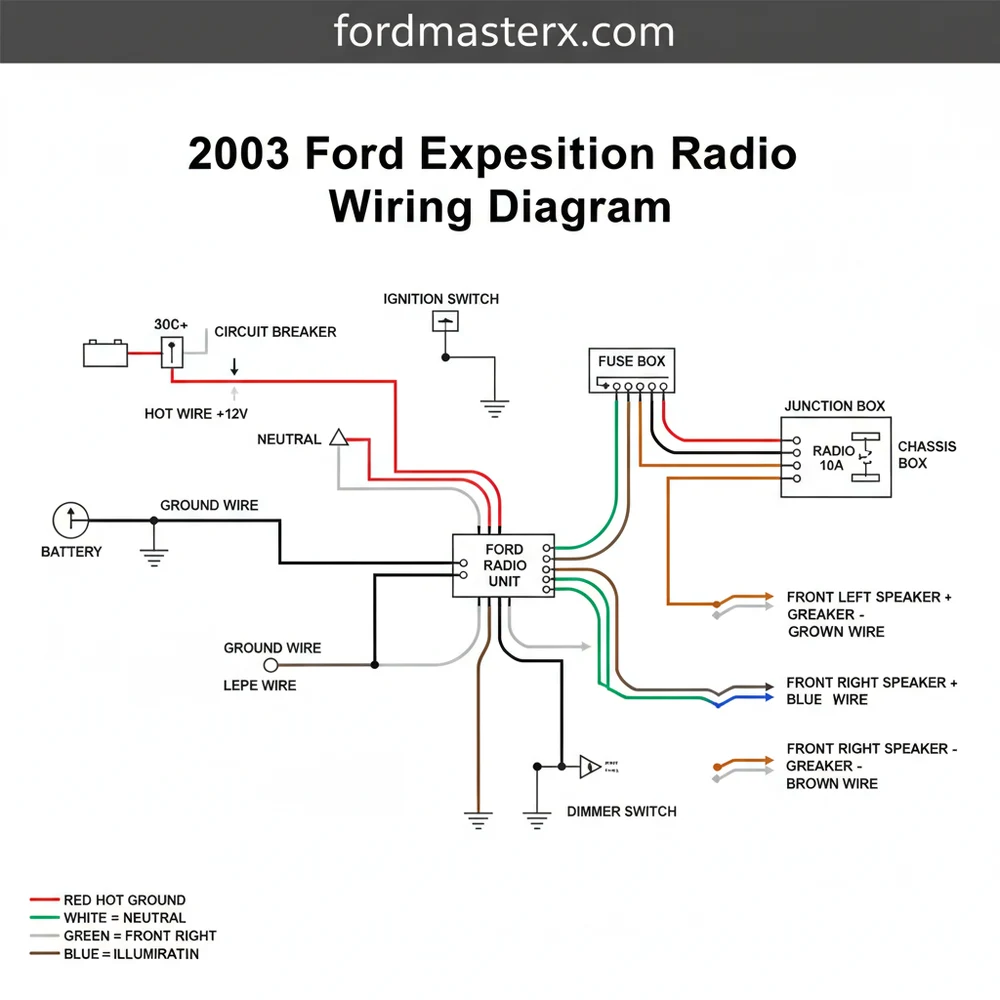
Ford Expedition Radio Wiring Diagram: Easy Setup Guide
The 2003 Ford Expedition radio wiring diagram identifies power and speaker circuits. The hot wire provides constant 12V for memory, while the neutral wire serves as the switched ignition source. A solid ground wire must connect to a common terminal to prevent interference and ensure the audio system operates efficiently.
📌 Key Takeaways
- Provides a visual map for power, ground, and speaker signal routing.
- The hot wire is the most critical component for maintaining radio presets.
- Always disconnect the battery before touching any ground wire to avoid electrical shorts.
- Use a multimeter to verify the traveler wire signal when using steering wheel controls.
- Use this diagram when upgrading to an aftermarket head unit or bypass amp.
Upgrading the factory head unit in your full-size SUV requires a precise understanding of the 2003 Ford Expedition radio wiring diagram to ensure a seamless integration of modern technology with your vehicle’s existing electrical architecture. Whether you are installing a touchscreen navigation system or simply replacing a faulty factory unit, having a clear map of the wire colors and pin locations is essential to prevent blown fuses or damage to the sensitive electronic control modules. This guide provides a comprehensive breakdown of the audio circuitry, helping you identify power leads, speaker polarities, and specialized signal wires for a professional-grade installation.
Main Diagram Description and Component Identification
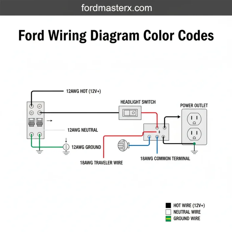
The 2003 Ford Expedition radio wiring diagram is primarily divided into two or three main harness connectors, depending on whether your vehicle is equipped with the standard audio package or the premium Mach Audio system with an external amplifier and subwoofer. The main 24-pin connector handles the primary power, ground, and front speaker outputs. In most configurations, the hot wire—which provides constant 12V power to maintain clock and preset memory—is typically a light green/violet wire. The ignition or switched power wire, which carries voltage only when the key is in the accessory or run position, is often pink/black.
Identifying the ground wire is the most critical step for system stability; in this model, it is usually a black/light green wire. While residential systems might refer to a neutral wire for completing a circuit, in an automotive DC environment, the chassis ground serves this function. The wiring diagram also specifies the traveler wire equivalents used for steering wheel controls or speed-sensitive volume signals. For the speakers, the diagram uses a color-pairing system: for example, the left front speaker typically uses an orange/light green wire for positive and light blue/white for negative. If your Expedition features the factory subwoofer, a smaller secondary harness will contain the low-level signal wires and the 5V or 12V amplifier trigger wire, which is essential for “waking up” the factory amp when the radio turns on.
The 2003 Ford Expedition uses a “floating ground” system for its speakers. This means you should never bridge the negative speaker wires together or connect them to the vehicle chassis, as this can cause the internal amplifier of your new radio to overheat and fail.
Step-by-Step Installation and Wiring Guide

Reading the 2003 Ford Expedition radio wiring diagram is the first stage of a successful install. Follow these steps to ensure your wiring is secure, functional, and safe.
Step 1: Preparation and Safety
Before touching any wires, disconnect the negative terminal of your battery. This prevents accidental shorts that could trigger an airbag light or blow the main PCM fuses. Gather your tools, including a 7mm socket, panel removal tools, wire strippers, and a soldering iron or high-quality crimp connectors. Ensure you have a multimeter handy to verify the voltage of your power leads before making permanent connections.
Step 2: Accessing the Radio Harness
Carefully pry the trim bezel surrounding the radio and climate controls. The 2003 model utilizes several clips that can be brittle. Once the trim is removed, unscrew the 7mm bolts holding the factory head unit in place. Pull the unit forward and depress the tabs on the plastic connectors to release the factory harness.
Step 3: Identifying the Primary Power Circuits
Using the diagram, locate your hot wire (constant 12V) and your ignition wire (switched 12V). If you are using an aftermarket adapter harness, the colors will likely follow the EIA standard (Yellow for constant, Red for switched). However, if you are hard-wiring, you must match the vehicle’s light green/violet (constant) and pink/black (switched) wires to the appropriate inputs on your new radio.
Step 4: Establishing a Solid Ground
The ground wire (black/light green) must be connected to the new radio’s ground lead. In some custom installations involving high-wattage amplifiers, you might find a common terminal or a brass screw on the dash frame to use as an auxiliary grounding point. A solid ground prevents the “alternator whine” often heard in poorly installed systems.
Step 5: Wiring the Speaker Outputs
The 2003 Ford Expedition radio wiring diagram lists eight specific wires for the four main speakers.
- ✓ Front Left: Orange/Light Green (+) and Light Blue/White (-)
- ✓ Front Right: White/Light Green (+) and Dark Green/Orange (-)
- ✓ Rear Left: Gray/Light Blue (+) and Tan/Yellow (-)
- ✓ Rear Right: Orange/Red (+) and Brown/Pink (-)
Step 6: Managing the Factory Amplifier
If your Expedition has the Mach Audio system, you will see a smaller connector with a Dark Blue/White wire. This is the amplifier turn-on lead. You must connect this to the “Remote Turn-on” wire of your new radio. Without this connection, the speakers will remain silent because the factory amplifier will never receive the signal to power up.
Do not confuse automotive DC wiring with household AC wiring. While a house uses a neutral wire and a hot wire with a brass screw for termination, automotive systems use the metal chassis as the negative return. Never attempt to use household wire nuts or electrical tape alone for automotive connections; use crimp caps or solder with heat shrink tubing.
Common Issues & Troubleshooting

One of the most frequent problems encountered when using the 2003 Ford Expedition radio wiring diagram is the “no sound” condition. This usually happens in vehicles with the premium sound package when the remote turn-on wire is not connected. If the radio powers on and shows a display but produces no audio, verify that the amplifier trigger wire is receiving at least 12V when the unit is active.
Another common issue is a loud “pop” sound when the radio is turned on or off. This often indicates that the voltage signal sent to the factory amplifier is too high. Many Ford factory amplifiers require a 5V trigger rather than the 12V trigger provided by aftermarket radios. In this case, you may need a 12V-to-5V step-down resistor. If you experience radio memory loss (where the clock resets every time you turn off the car), you likely have the hot wire and the switched ignition wire reversed. The constant power must be connected to the circuit that shows 12V voltage even when the key is removed from the ignition.
Tips & Best Practices for Audio Wiring
To ensure the longevity of your audio system, always pay attention to the wire gauge. For the main power and ground, 16-gauge or 18-gauge wire is typically sufficient for a standard head unit. However, if you are adding an external power-hungry amplifier, you will need to run a dedicated 4-gauge or 8-gauge wire directly from the battery to a common terminal or distribution block.
Always use a vehicle-specific wiring harness adapter. These plug directly into the Ford factory connectors and provide standardized color-coded pigtails that match your new radio. This prevents you from having to cut the factory wires, which preserves the vehicle’s resale value and makes troubleshooting significantly easier.
When making connections, soldering is the gold standard. It provides a permanent, low-resistance bond that won’t vibrate loose over rough terrain. If you must use crimp connectors, ensure you use a professional ratcheting crimp tool rather than standard pliers. Proper insulation is equally important; heat shrink tubing is superior to electrical tape, which can lose its adhesive properties in the extreme heat or cold a vehicle dash experiences throughout the year. Finally, always secure your wiring loom with zip ties to prevent rattling and to keep wires away from the sharp metal edges of the dashboard sub-structure. Following these professional standards while referencing the 2003 Ford Expedition radio wiring diagram will ensure your new sound system performs flawlessly for years to come.
Frequently Asked Questions
Where is the radio wiring harness located?
The primary radio wiring harness is located directly behind the factory head unit in the center dashboard stack. You must remove the dash trim bezel to access the connectors. Some models with premium audio may have additional harnesses leading to a factory amplifier located behind the right-rear quarter panel.
What does the radio wiring diagram show?
This diagram provides a pin-by-pin breakdown of the factory connector, showing which colors correspond to the front and rear speakers. It also highlights the hot wire for constant power, the switched ignition lead, the illumination wire, and the ground wire connection necessary for completing the electrical circuit.
How many connections does the Expedition radio have?
The standard 2003 Ford Expedition typically utilizes a 24-pin main harness for power and speakers. If equipped with the Mach Audio system, you will find an additional smaller harness for the subwoofer and amplifier turn-on traveler wire, which requires a specific integration adapter for aftermarket use.
What are the symptoms of a bad radio ground?
A poorly connected ground wire usually results in an audible engine whine, static, or the radio resetting when the volume is increased. If the common terminal is loose or corroded, the radio may fail to turn on entirely or experience intermittent power loss during vehicle operation.
Can I install an aftermarket radio myself?
Yes, installing a radio is a manageable DIY project with this wiring diagram. Using a vehicle-specific harness adapter allows you to match the factory wires to your new stereo’s colors on your workbench, making the final installation a simple plug-and-play process inside the vehicle.
What tools do I need for this wiring task?
You will need a 7mm socket or trim removal tool to pull the dash panel. For the wiring, use wire strippers, a crimping tool with butt connectors, or a soldering iron with heat shrink tubing. A multimeter is also recommended to test the hot wire and neutral wire.