The Ford Engine Encyclopedia: A Comprehensive Analysis of Displacement, Architecture, and Technical Evolution
The trajectory of the Ford Motor Company is defined not merely by the vehicles it produced, but by the relentless evolution of its powertrains. From the democratization of V8 power in the 1930s to the plasma-coated cylinder bores of the modern era, Ford’s engine engineering reflects nearly a century of industrial innovation, regulatory adaptation, and performance pursuit.
This report serves as an exhaustive technical reference and historical analysis of Ford engine families, synthesizing data on displacement, bore, stroke, block architecture, and identification metrics.
The following analysis moves beyond simple lists of cubic inches. It categorizes engines by architectural families—the only accurate method for identification given Ford’s tendency to utilize identical displacement figures (e.g., 351 cubic inches) across radically different mechanical designs.
We explore the engineering rationale behind the shift from flatheads to overhead valves, the impact of thin-wall casting techniques on the “Windsor” family, the airflow dynamics of the “Cleveland” canted-valve heads, and the intricate fluid dynamics of the modern EcoBoost and Coyote platforms.
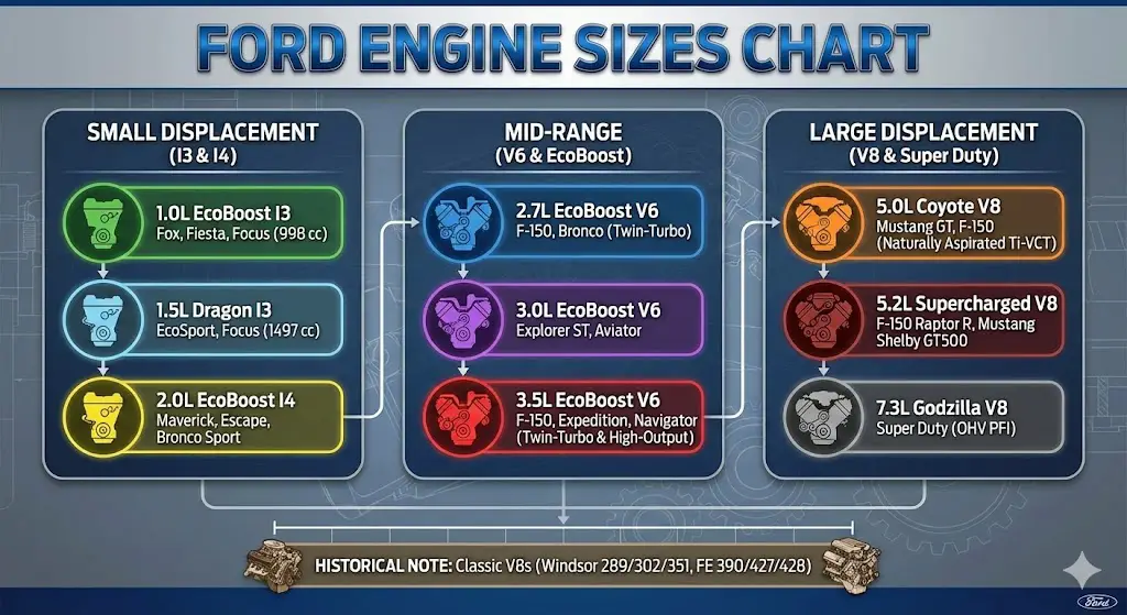
A Legacy of Power
From the revolutionary Flathead V8 to the high-efficiency EcoBoost, Ford has spent over a century defining and redefining the internal combustion engine. This guide visually breaks down the key engine families, their performance, and how they’ve evolved.
Today’s Power Players
Ford’s current lineup is dominated by three core engine philosophies. This chart shows the approximate popularity mix in new vehicle sales, highlighting the massive adoption of EcoBoost technology.
What This Shows
The EcoBoost family, with its turbocharged, direct-injection technology, represents the majority of engines sold, offering a blend of power and efficiency.
The legendary V8 remains a vital part of the lineup, powering trucks and performance vehicles like the Mustang.
The PowerBoost Hybrid is the new challenger, merging electric torque with gasoline power for incredible capability.
The EcoBoost Revolution
The EcoBoost line proves that size isn’t everything. By using turbocharging, Ford can extract immense power from smaller, more fuel-efficient engines. This chart compares the horsepower ratings of the most common EcoBoost variants found in vehicles from the Mustang to the F-150.
The Enduring Roar: V8 Evolution
The Ford V8 is an American icon. While its core configuration remains, its performance has transformed. This chart tracks the approximate peak horsepower of Ford’s mainstream V8 engines over the last 50 years, showing the dramatic impact of modern technology like computer control and dual overhead cams.
The Future: PowerBoost Hybrid
Ford’s hybrid technology isn’t just for efficiency—it’s for performance. The F-150’s 3.5L PowerBoost system is a prime example. This chart breaks down the total torque output, showing how the electric motor and gasoline engine stack up.
Gas + Electric = Max Torque
The stacked bar shows the torque contribution from both the 3.5L V6 EcoBoost engine and the integrated electric motor.
How to Read a Ford Engine Name
Ford’s engine names can seem complex, but they follow a clear pattern. Here is a simple breakdown of what each part means, using “3.5L EcoBoost V6” as an example.
Displacement
The total volume of the engine’s cylinders, measured in liters.
Family / Technology
The engine’s brand name, indicating its technology (e.g., EcoBoost, Power Stroke).
Configuration
The number and arrangement of cylinders (e.g., V6, I-4, V8).
The Flathead Genesis (1932–1953)
The internal combustion engine was far from a novelty in 1932, but the configuration Ford introduced that year shifted the automotive landscape permanently. The Ford Flathead V8, or L-head, brought multi-cylinder smoothness and torque to the masses, ending the era where V8s were the exclusive purview of luxury marques like Cadillac or Lincoln.
The Architecture of the L-Head
The defining characteristic of the Flathead V8 is its monobloc construction. In an era where many manufacturers cast cylinders separately from the crankcase, Ford pioneered the technique of casting the entire V8 block and crankcase as a single unit. This required immense metallurgical expertise and sophisticated foundry techniques to manage the complex sand cores required for the water jackets and internal passages.
The valves are located within the engine block, adjacent to the cylinders, opening upward into a combustion chamber carved into the cylinder head. This “L-head” design resulted in a simplified, flat cylinder head—hence the name. While this design reduced manufacturing costs and complexity (no pushrods or rocker arms were required), it presented significant airflow challenges. The air-fuel mixture had to make a tortuous 90-degree turn to enter the cylinder, and exhaust gases had to travel through the block to exit, transferring massive amounts of heat to the cooling system—a notorious trait of the Flathead that challenged radiators of the era.
Flathead Evolution and Displacement
The Flathead family evolved through several generations, generally categorized by the number of studs used to secure the cylinder heads (21-stud, 24-stud) and their displacement.
The Early V8-18 and V8-40 (1932–1934)
The initial offering displaced 221 cubic inches. It utilized a 3.0625-inch bore and a 3.750-inch stroke, producing 65 horsepower in its debut year. By 1933, the introduction of aluminum cylinder heads and improved compression bumped output to 75 horsepower. These early engines are easily identified by their 21-stud head bolt pattern and the water pumps mounted directly to the cylinder heads.
The 239 and the Mercury Connection (1939–1953)
To differentiate the mid-range Mercury brand, Ford introduced a larger 239 cubic inch version in 1939. This engine utilized a larger 3.1875-inch bore while retaining the 3.750-inch stroke. This 239 variant eventually became the standard Ford powerplant post-WWII, producing roughly 100 horsepower. It represents the “classic” Flathead widely used in hot rodding due to its thicker cylinder walls and improved 24-stud architecture.
The V8-60 (1937–1940)
In response to European tax horsepower ratings and a desire for an economy engine, Ford produced the V8-60. Displacing a diminutive 136 cubic inches with a 2.600-inch bore, this engine was physically smaller and significantly lacking in torque compared to its larger siblings. While largely a commercial failure in heavy US sedans, the V8-60 found a second life in midget racing due to its compact size and light weight.
The “Big” Flathead: 337 Cubic Inches
Often overlooked, the largest factory Flathead was the 337 cubic inch V8 produced for heavy trucks and Lincoln passenger cars (1949–1951).
- Displacement: 337 cu in (5.5 L)
- Bore: 3.500 in
- Stroke: 4.375 in
- Power: 154 hp
- Torque: 275 lb-ftThis massive engine featured a rear-mounted distributor (unlike the front-mounted units on Ford/Mercury flatheads) and was designed for low-RPM torque. It was the final gasp of the L-head architecture before Lincoln moved to overhead valves in 1952.
Technical Limitations and Legacy
By the early 1950s, the Flathead had reached its volumetric efficiency limit. The tortuous intake and exhaust paths restricted high-RPM breathing, and the thermal load on the block from the internal exhaust runners limited compression ratios. Despite these limitations, the Flathead established the V8 format as the standard for American performance, fostering an aftermarket industry of intake manifolds (Edelbrock) and cylinder heads (Offenhauser) that sought to correct the factory airflow deficiencies.
The Overhead Valve Transition – The Y-Block (1954–1962)
The 1950s sparked a horsepower war that rendered the Flathead obsolete. To compete with General Motors’ high-compression overhead valve (OHV) engines, Ford introduced the Y-Block in 1954.
Deep-Skirt Block Architecture
The “Y-Block” nomenclature is derived from the engine’s deep-skirted cast-iron block. Unlike the Chevy small block, where the oil pan rail is level with the crankshaft centerline, the Y-Block’s casting extends well below the crankshaft. Viewed from the end, the block and bearing caps form a “Y” shape. This design imparted immense rigidity to the bottom end, providing a stable foundation for the crankshaft and making the engine exceptionally smooth.
However, this rigidity came with a weight penalty. The Y-Block is heavy for its displacement compared to the later Windsor engines. Another distinct feature is the stacked intake port arrangement (over/under) rather than the side-by-side arrangement found on most V8s, which allows for visually identifying Y-Blocks by their unique exhaust manifold bolt patterns.
Displacement Progression and Specifications
The Y-Block followed a rapid evolution of bore and stroke increases to keep pace with vehicle weight and competitor horsepower.
The 239 and 256 (1954)
The introductory 1954 engines displaced 239 cubic inches (Ford) and 256 cubic inches (Mercury).
- 239 Specs: 3.500″ Bore x 3.100″ Stroke.
- 256 Specs: 3.625″ Bore x 3.100″ Stroke.The 1954 239 engines differ significantly from later Y-Blocks, utilizing different cam bearings and oiling passages, making parts interchangeability difficult.
The 272 and 292 (1955–1962)
In 1955, the bore was increased to 3.625″ (for the 272) and 3.750″ (for the 292), with the stroke growing to 3.300″.
- 272: Standard engine for most Fairlanes and trucks.
- 292: Known as the “Thunderbird V8,” this became the standard performance option. It served in trucks well into the 1960s due to its durability.6
The 312: Peak Y-Block Performance (1956–1960)
The 312 is the most desirable Y-Block, powering the iconic 1956 and 1957 Thunderbirds.
- Displacement: 312 cu in
- Bore: 3.800 in
- Stroke: 3.440 in
- Crankshaft Specifics: The 312 utilizes larger main bearing journals than the 292/272. While a 292 crank fits in a 272 block, a 312 crank requires main journals to be turned down or the block line-bored to fit a 292 block.
- Supercharging: In 1957, a Paxton-supercharged 312 produced 300 horsepower, a remarkable figure for the era.
The Oiling Issue
A known idiosyncrasy of the Y-Block is its top-end oiling system. Oil is fed to the rocker shafts via a passage that aligns with a groove in the cam bearing. As these bearings wore or spun, oil flow to the heads was restricted, leading to noisy valvetrains. Contemporary mechanics often installed external copper oil lines feeding the valve covers directly to bypass the internal blockage.6
The Inline Six Dynasty (1960–1996)
While V8s garnered the headlines, Ford’s inline-six engines were the backbone of the company’s economy cars and light trucks. These engines are categorized into two distinct families: the small “Thriftpower” sixes and the large truck sixes.
The Thriftpower “Small Six” (144, 170, 200, 250)
Introduced with the 1960 Ford Falcon, this engine family was designed for compact packaging.
The Integral Intake “Log” Head
The defining feature of the 144/170/200 engines is the intake manifold, which is cast integrally with the cylinder head. This “log” style manifold reduced production costs and hood clearance requirements but severely restricted performance potential, as the manifold could not be upgraded.
Specifications and Evolution
- 144 cu in (1960–1964): 3.500″ Bore x 2.500″ Stroke. The economy leader, but arguably underpowered for American highways.
- 170 cu in (1961–1972): 3.500″ Bore x 2.940″ Stroke. The stroke increase provided much-needed torque for the heavier Falcon and early Mustang.
- 200 cu in (1963–1983): 3.680″ Bore x 3.126″ Stroke. The definitive Mustang six-cylinder.
- Bearing Update: Mid-1965 saw an upgrade from 4 main bearings to 7 main bearings, significantly reducing crankshaft flex and vibration.
The 250 Cubic Inch Six
Introduced in 1969, the 250 utilizes a unique block with a deck height 1.66 inches taller than the 170/200 to accommodate a massive 3.91-inch stroke.
- Bellhousing Difference: Crucially, the 250 shares the Small Block V8 (Windsor) bellhousing pattern, whereas the 144/170/200 use a smaller, unique pattern. This allows the 250 to accept stronger transmissions like the C4 and T-5 designed for V8s.
The “Big Six” (240 and 300)
Completely distinct from the Thriftpower family, the 240/300 engines were built for full-size cars and trucks.
- 300 cu in (4.9L): 4.00″ Bore x 3.98″ Stroke.
- Construction: Heavy-duty cast iron block, 7 main bearings, and gear-driven timing (no chain to stretch or break).
- Applications: The 300-6 is legendary in F-Series trucks for high-torque durability, often outlasting the chassis it powers. It remained in production until 1996.
The Small Block V8 – The Windsor Family (1962–2001)
The “Windsor” family represents the archetypal Ford V8. Introduced in 1962 to replace the heavy Y-Block, it utilized modern “thin-wall” casting techniques to reduce weight while maintaining strength.
Windsor Nomenclature and Architecture
The name “Windsor” differentiates this engine family (manufactured largely in Windsor, Ontario) from the later “Cleveland” family. The architecture features a 90-degree cylinder bank angle, a front-mounted distributor, and water passages routed through the intake manifold.
Comprehensive Displacement Data
The following table details the evolution of the Windsor platform:
| Engine | Displacement | Bore | Stroke | Deck Height | Conn. Rod Length | Notes |
| 221 | 221 cu in (3.6L) | 3.500″ | 2.870″ | 8.206″ | 5.155″ | Introduced 1962. First “Fairlane V8”. |
| 260 | 260 cu in (4.3L) | 3.800″ | 2.870″ | 8.206″ | 5.155″ | Used in earliest 1964. Mustangs and Sunbeam Tigers. |
| 289 | 289 cu in (4.7L) | 4.000″ | 2.870″ | 8.206″ | 5.155″ | The muscle car icon. K-Code HiPo versions available. |
| 302 (5.0) | 302 cu in (4.9L) | 4.000″ | 3.000″ | 8.206″ | 5.090″ | Stroke increased. Rod shortened. The longest-running variant. |
| 351W | 351 cu in (5.8L) | 4.000″ | 3.500″ | 9.503″ | 5.956″ | Taller deck block introduced in 1969. |
The 302 vs. 351W Distinction
A frequent source of confusion is the physical difference between the 302 and the 351W. While they share the same 4.000-inch bore and general layout, they are not externally identical.
- Deck Height: The 351W block is approximately 1.3 inches taller than the 302 (9.503″ vs 8.206″). This allows for the longer 3.500-inch stroke.
- Intake Manifolds: Because the cylinder banks are pushed further apart by the taller deck, the intake manifold for a 351W is significantly wider than that of a 302. They are not interchangeable.
- Firing Order:
- Early 221/260/289/302: 1-5-4-2-6-3-7-8
- 351W and 1982+ 302 HO: 1-3-7-2-6-5-4-8
- Implication: When swapping camshafts, one must match the camshaft firing order to the spark plug wire routing. Installing a 351W firing order cam in an older 302 block is a common performance upgrade (due to better cam availability), provided the plug wires are re-routed.
The 5.0L HO Era (1982–1995)
The “5.0 Liter” moniker revitalized Ford performance in the 1980s. While technically displacing 4,942cc (closer to 4.9L), Ford marketing dubbed it the 5.0 to distinguish it from the 4.9L Inline Six.
- 1985: Introduction of hydraulic roller lifters in the block, reducing friction and allowing for more aggressive cam profiles.
- 1986: Introduction of sequential multi-port electronic fuel injection (EFI) and the “E6” swirl-port heads (which improved torque but limited high-RPM power).
- 1987-1993: The “E7” truck heads were fitted to the Mustang, creating the legendary Fox Body performance recipe.
The Mid-Block Controversy – 335 Series (Cleveland & Modified)
In the late 1960s, Ford needed an engine that could breathe better than the Windsor to compete in Trans-Am racing but fit in mid-size chassis where the massive FE series was too tight. The solution was the 335 Series, manufactured primarily at the Cleveland, Ohio plant.
The 351 Cleveland (351C)
The 351C is revered for its cylinder head design. Unlike the inline valves of the Windsor, the Cleveland featured canted valves (tilted in two planes). This arrangement allowed for significantly larger valves (up to 2.19″ intake) and straighter ports, resulting in massive airflow capability.
- Production: 1970–1974 (USA).
- Architecture: The timing chain is housed inside an extension of the block casting (integrated timing cover), unlike the Windsor’s separate aluminum cover.
- 2V vs. 4V Heads:
- 2V (2-Barrel): Smaller ports, open combustion chambers. Good for low-end torque.
- 4V (4-Barrel): Massive intake ports. While offering incredible top-end power, the port velocity was often too low for street driving, making the car feel sluggish at low RPM.
The Modifieds: 351M and 400
As the 1970s progressed, emissions regulations and the need for heavy-vehicle torque led to the 400 and 351M.
- 400 (1971–1982): To increase stroke to 4.00 inches, Ford increased the deck height of the Cleveland design to 10.297 inches. This is the tallest deck of any Ford small/mid-block.
- 351M (1975–1982): Standing for “Modified” (though some sources joke “Michigan” or “Mediocre”), this engine was a destroked 400. It utilized the tall-deck 400 block with a 3.500-inch stroke crankshaft.
Crucial Interchange Data:
- Bellhousing: The 351C shares the Small Block (Windsor) bellhousing pattern. The 351M and 400 share the Big Block (385 Series/460) bellhousing pattern. This is a critical distinction for transmission swaps.
- Parts Swapping: 351C heads bolt directly onto 351M/400 blocks. This allows engine builders to create a “Clevor” (Cleveland heads on a Windsor block) or a high-compression 400 by using early 351C closed-chamber heads on a 400 block, unlocking vast torque potential suppressed by the factory smog-era compression ratios.
Heavy Metal – FE and 385 Series Big Blocks
When maximum displacement was required for luxury liners or drag strip dominance, Ford turned to its big blocks.
The FE Series (1958–1976)
The FE (Ford-Edsel) engine is perhaps the most versatile in Ford history, powering everything from pickup trucks to the Le Mans-winning GT40.
FE Identification
FE engines are visually distinct: the valve covers bolt partially to the intake manifold, as the pushrods pass through the intake casting itself. The block features a deep skirt similar to the Y-Block.22
FE Displacement Chart
| Engine | Bore | Stroke | Application |
| 332 | 4.000″ | 3.300″ | Early Edsel/Ford use. |
| 352 | 4.000″ | 3.500″ | The volume seller. |
| 390 | 4.050″ | 3.780″ | The standard muscle car big block (GT, GTA). |
| 427 | 4.230″ | 3.780″ | Racing engine. Cross-bolted mains. Side-oiler oiling system. |
| 428 | 4.130″ | 3.980″ | Cobra Jet. Longer stroke, smaller bore than 427 for streetability. |
Performance Insight: The 427 was a race-bred engine with a 4.23-inch bore that pushed the limits of the cylinder wall thickness, often requiring sonic checking. The 428 was developed as a cheaper, more street-friendly alternative for the Cobra Jet Mustang, achieving displacement via stroke rather than bore.
The 385 Series (1968–1997)
Named after the 3.85-inch stroke of the 460, this family replaced the FE. It represents a more modern, thin-wall casting design with poly-angle valves similar to the Cleveland.
- 429 cu in: 4.360″ Bore x 3.590″ Stroke. The choice for the Boss 429 (with unique hemi-style heads) and Cobra Jet Mustangs.
- 460 cu in: 4.360″ Bore x 3.850″ Stroke. Used extensively in Lincolns and F-250/350 trucks.
- Legacy: The 460 is known for robust strength. The block can handle significant overboring (up to 0.080″ in some cases), and stroker kits can push displacement to 557 cubic inches using the stock block.
The Modular Revolution (1991–Present)
In the early 1990s, Ford abandoned the pushrod architecture that had served it for 60 years in favor of Overhead Cam (OHC) technology. The goal was to reduce friction, improve efficiency, and meet tightening emissions standards.
Modular Architecture
The term “Modular” refers to the manufacturing plant tooling strategy, allowing quick changes between V8 and V10 production. All Modular engines share a 100mm (3.937″) bore spacing.23
The 4.6L V8
- Bore x Stroke: 90.2mm x 90.0mm (Square design).
- 2-Valve (SOHC): The reliable taxi/police engine. ~215-250 hp.
- 3-Valve (SOHC): Introduced in 2005 Mustang. Variable Cam Timing (VCT) added. ~300 hp.
- 4-Valve (DOHC): The performance variant. Used in the Lincoln Mark VIII and SVT Cobra. The 2003-2004 “Terminator” Cobra used a supercharged 4.6L DOHC block with iron construction for durability, producing 390+ hp.
The 5.4L V8
To achieve more torque for trucks, Ford increased the deck height to accommodate a 4.165-inch stroke.
- Deck Height: 10.079 inches (compared to 8.937 for the 4.6).
- Width: The 5.4L DOHC engine is physically massive—wider than a 460 Big Block—making it difficult to swap into classic cars without cutting shock towers.
The 6.8L V10
Essentially a 5.4L V8 with two cylinders added.
- Firing Order: 1-6-5-10-2-7-3-8-4-9.
- Balance: A split-pin crank and a balance shaft were required to quell the vibrations inherent in the V10 72-degree firing interval.
The Coyote and Voodoo (2011–Present)
The “Coyote” 5.0L engine was Ford’s answer to the LS3 from GM. It brought the “5.0” name back, but on the Modular OHC architecture.
5.0L Coyote Architecture
To extract 5.0 liters from the Modular’s 100mm bore spacing, Ford pushed the bore to 92.2mm (Gen 1/2) and 93mm (Gen 3).
- Gen 1 (2011-2014): 412-420 hp. Port injection.
- Gen 2 (2015-2017): 435 hp. Improved cylinder heads and mid-lock phasers.
- Gen 3 (2018+): 460 hp. Added Direct Injection (dual fuel system).
- PTWA Technology: To achieve the 93mm bore in Gen 3, Ford removed the iron cylinder liners and used Plasma Transfer Wire Arc spray to coat the aluminum cylinders with steel. This reduced weight and increased displacement.
The Voodoo 5.2L (Shelby GT350)
- Flat-Plane Crank: The Voodoo is unique in American V8 history for using a flat-plane crankshaft (crank pins at 180 degrees) rather than a cross-plane (90 degrees).
- Physics: This creates an alternating firing order between banks (L-R-L-R), maximizing exhaust scavenging and allowing an 8,250 RPM redline.
- Vibration: The design lacks primary balance, creating a distinct “buzz” and requiring unique motor mounts and ancillary brackets to prevent vibration damage.
The Predator 5.2L (Shelby GT500)
For the supercharged GT500 (760 hp), Ford returned to a Cross-Plane Crankshaft. The vibration of the flat-plane crank was deemed too risky for the stresses of forced induction at that power level. It shares the 5.2L block (94mm bore) but is a different animal structurally.
The EcoBoost Strategy
“EcoBoost” signifies the combination of Turbocharging and Gasoline Direct Injection (GTDI).
3.5L EcoBoost V6
- Gen 1 (2011-2016): Single timing chain. Direct injection only. Known for carbon buildup on intake valves due to lack of fuel wash.
- Gen 2 (2017+): Dual injection (Port + Direct). Dual timing chains (one per bank) to resolve stretch issues. This is the engine in the Ford GT (647 hp) and Raptor.
2.7L “Nano” EcoBoost
- Material: Compacted Graphite Iron (CGI). This material is twice as strong as grey iron, usually reserved for diesel engines.
- Design: A “clean sheet” design, not based on previous Duratec architectures. It uses a two-piece block design.
Diesel Power – The Power Stroke
Ford’s diesel history is a tale of two eras: the Navistar partnership and the in-house Ford era.
The 7.3L Power Stroke (1994.5–2003)
- Manufacturer: Navistar (International T444E).
- Injection: HEUI (Hydraulic Electronic Unit Injection). High-pressure engine oil fires the injectors.
- Reputation: The “Gold Standard” for reliability. Lacks modern power, but rarely fails catastrophically.32
The 6.0L Power Stroke (2003–2007)
- Changes: Variable Geometry Turbo (VGT) introduced for response.
- Failures: The EGR cooler and oil cooler were prone to clogging, leading to overheating and blown head gaskets. The TTY (Torque to Yield) head bolts were insufficient for cylinder pressures once the EGR failed.
The 6.7L “Scorpion” (2011–Present)
- Manufacturer: Ford (In-house).
- Reverse Flow Heads: Intake ports are on the outside of the head; exhaust ports exit into the engine valley.
- Single Sequential Turbo (SST): A unique dual-compressor wheel turbo mounted in the valley. This reduces lag to near zero.
- Output: Started at 390 hp / 735 lb-ft. Now exceeds 500 hp / 1200 lb-ft (High Output version).
Identification and Decoding
Casting Numbers
Ford part numbers generally follow a 4-character prefix structure: D1VE.
- Decade: A=40s, B=50s, C=60s, D=70s, E=80s, F=90s.
- Year: Second digit (C8 = 1968).
- Vehicle: Third digit (A=Full Size, Z=Mustang, T=Truck).
- Part: Fourth digit (E=Engine).
- Example: C9ZE indicates a 1969 Mustang Engine part.
Bellhousing Patterns
Critical for transmission swaps.
- Small Block (Windsor): 6-bolt pattern. Used on 289, 302, 351W, 351C, 250 I6, and 4.6L/5.0L Coyote.
- Big Block (385 Series): Used on 429, 460, 351M, and 400.
- FE Series: Rounder top. 390, 427, 428.
- Flathead: Early style integral bellhousing.
4-Cylinder Engines
The “Kent” (1.6L)
An OHV pushrod engine used in the Fiesta and Formula Ford racing. A crossflow head design.
The 2.3L Lima (OHC)
The “Pinto” engine. SOHC, belt-driven. Used in the Mustang II, Fox Body Mustang (Turbo GT), and Merkur XR4Ti. A robust iron block often used in mini-stock racing.
Zetec and Duratec
- Zetec: Iron block, DOHC. Used in Focus and Escort ZX2.
- Duratec: Aluminum block (Mazda MZR design). The 2.0L and 2.3L variants powered the Focus and Ranger. This architecture is the basis for the 2.3L EcoBoost.
Conclusion
The evolution of Ford engines is a study in adaptation. From the Flathead’s quest for mass-production simplicity to the 7.3L Godzilla’s return to pushrods for density, Ford has continuously reinvented its powertrains. For the enthusiast, the “family” distinction—understanding that a 351M is not a 351W, or that a 5.0L Coyote is not a 5.0L Windsor—is the key to unlocking the potential of these machines. This report provides the foundational data necessary to navigate that complex history.


