Ford 300 Inline 6 Diagram: Complete Engine Layout Guide
A Ford 300 inline 6 diagram illustrates the robust structure and layout of this legendary engine. It identifies every major component, from the intake manifold to the ignition system, helping owners visualize the internal configuration. This guide simplifies maintenance tasks and troubleshooting for anyone working on this classic Ford powerplant.
📌 Key Takeaways
- Provides a visual map of the engine’s external and internal layout
- Identifying the intake and exhaust manifold configuration is crucial
- Ensure all vacuum lines are routed according to the system schematic
- Use the diagram to cross-reference bolt patterns and torque sequences
- Refer to this diagram during rebuilds or basic tune-up procedures
Finding an accurate ford 300 inline 6 diagram is often the first step in maintaining, repairing, or restoring one of the most legendary powerplants in automotive history. Known for its remarkable durability and low-end torque, the Ford 300 cubic inch (4.9L) engine has powered everything from farm trucks to delivery vans for decades. Whether you are a seasoned mechanic or a DIY enthusiast, having a clear visual reference of the engine’s internal and external architecture is crucial. This article provides a comprehensive overview of the engine layout, explaining how to interpret schematic drawings to solve mechanical issues and improve performance.
Understanding the Ford 300 Inline 6 Diagram and Layout
The Ford 300 inline 6 engine is celebrated for its simplistic, heavy-duty design. When viewing a comprehensive blueprint or schematic, the first thing you will notice is its longitudinal configuration. Unlike V-shaped engines, all six cylinders are arranged in a straight line, which provides ample room on either side of the block for servicing components. A standard ford 300 inline 6 diagram typically breaks the engine down into its primary cast-iron components: the engine block, the cylinder head, and the massive intake and exhaust manifolds.
One of the most distinct features of this engine’s structure is the gear-driven timing system. Unlike many modern engines that utilize a rubber belt or a metal chain, the 300 i6 uses two gears that mesh directly. In a technical layout, you will find these located behind the front timing cover. The diagram will also highlight the difference between the older carbureted versions and the later electronic fuel injection (EFI) models. Carbureted diagrams show a single-barrel or two-barrel intake manifold, whereas EFI schematics feature a more complex dual-exhaust manifold and a large aluminum upper intake plenum that sits prominently atop the engine.
Labeling in these diagrams usually follows a standard format. Components like the alternator, power steering pump, and air conditioning compressor are located on the accessory drive at the front. The distributor is positioned on the passenger side, driven by the camshaft. Understanding these locations through a visual guide allows you to quickly identify where sensors, such as the oil pressure sender or coolant temperature sensor, are threaded into the block or head. This overview serves as the foundation for any deeper mechanical exploration of the 4.9L system.
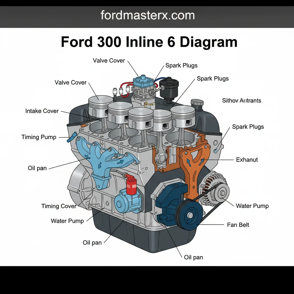
[DIAGRAM_PLACEHOLDER: A detailed technical schematic showing the Ford 300 Inline 6 engine from a 3/4 perspective. Labels indicate the Cylinder Head, Intake Manifold, Exhaust Manifold, Distributor, Water Pump, and Timing Cover. Arrows point to the Firing Order sequence 1-5-3-6-2-4 printed on the manifold.]
The Ford 300 inline 6 uses a firing order of 1-5-3-6-2-4. The cylinders are numbered 1 through 6 starting from the front of the vehicle (near the radiator) and moving toward the firewall.
Step-by-Step Guide to Reading and Applying the Diagram

Interpreting a ford 300 inline 6 diagram requires a systematic approach to ensure you are looking at the right section for your specific repair needs. Follow these steps to navigate the engine layout effectively:
Step 1: Orient Yourself with the Block
Before diving into specific systems, identify the front and rear of the engine on the blueprint. The front is characterized by the cooling fan and pulley assembly, while the rear connects to the bellhousing of the transmission. On a 300 inline 6, the “driver side” typically houses the intake and exhaust manifolds (non-crossflow design), while the “passenger side” contains the distributor, spark plugs, and fuel pump (on carbureted models).
Step 2: Trace the Ignition System
Using the schematic, locate the distributor. Note the direction of rotation (clockwise). Follow the lines representing spark plug wires from the distributor cap to the corresponding spark plugs. This is vital for maintaining the 1-5-3-6-2-4 firing order. If your wires are crossed, the engine will misfire or fail to start entirely.
Step 3: Map the Vacuum Lines
For many owners, the vacuum system is the most confusing part of the configuration. Use the diagram to trace the lines from the intake manifold to the brake booster, PCV valve, and EGR valve. On EFI models, these diagrams are often found on a sticker under the hood, but a digital schematic provides a much clearer view of where each plastic or rubber line originates.
Step 4: Identify the Cooling Circuit
Locate the water pump at the front of the block. Trace the flow from the lower radiator hose into the pump, through the engine block, up into the cylinder head, and out through the thermostat housing into the upper radiator hose. This help you understand where air pockets might get trapped during a coolant flush.
Step 5: Review Torque Sequences
If you are performing a head gasket replacement, the diagram will show a numbered sequence for the head bolts. You must follow this specific pattern (usually starting from the center and spiraling outward) to ensure even pressure across the gasket surface. Failure to follow this blueprint can lead to a warped head or immediate gasket failure.
Step 6: Locate the Timing Marks
Refer to the front-end section of the layout to find the timing pointer and the harmonic balancer marks. This is essential for setting the base ignition timing. On the 300 i6, these marks are often obscured by decades of grease, so knowing exactly where to look on the diagram saves significant time.
Always disconnect the battery before working on electrical components identified in the diagram. When working near the cooling system, ensure the engine is completely cool to avoid high-pressure steam burns.
Common Issues and Diagram-Based Troubleshooting

The Ford 300 inline 6 is nearly indestructible, but it does have specific “weak points” that a diagram can help you diagnose. One of the most common issues is a rough idle or hesitation, often caused by vacuum leaks. By referring to the vacuum system schematic, you can perform a “smoke test” or use a vacuum gauge to check each port identified on the manifold. If the gauge shows low or fluctuating pressure, the diagram helps you pinpoint which specific gasket or hose is likely the culprit.
Another frequent problem involves the exhaust manifold. Due to the length of the inline-six head, the exhaust manifold is subject to significant heat expansion and contraction, which can lead to cracked manifolds or broken mounting bolts. A structural diagram shows the location of all thirteen manifold bolts. If you hear a “ticking” sound that goes away as the engine warms up, use the layout to check the bolts at the very front and very rear of the head, as these are the most prone to snapping.
Finally, if you experience a “no-start” condition, the electrical schematic helps you trace the path from the ignition switch to the solenoid, and finally to the starter motor. By identifying these test points on the diagram, you can use a multimeter to find exactly where the voltage is dropping.
Tips and Best Practices for Maintenance
To keep your Ford 300 running for hundreds of thousands of miles, follow these professional recommendations based on the engine’s unique configuration:
- ✓ Use High-Zinc Oil: Because the 300 i6 uses a flat-tappet camshaft design, it requires oil with adequate ZDDP (zinc) content to prevent premature cam lobe wear.
- ✓ Upgrade to Metal Timing Gears: Some factory models used “fiber” or composite cam gears to reduce noise. When replacing them, consult your diagram and choose heavy-duty metal gears for ultimate reliability.
- ✓ Check the PCV System: A clogged PCV valve can cause oil leaks by increasing crankcase pressure. Locate the PCV in your diagram (usually in the valve cover) and replace it every 30,000 miles.
- ✓ Manifold Heat Shielding: Since the intake and exhaust are on the same side, heat soak can be an issue. Ensure your heat shields are in place according to the system layout.
If you are struggling with a manifold leak, many enthusiasts switch to the EFI-style dual exhaust manifolds on older carbureted engines. This provides better flow and reduces the likelihood of the manifold cracking under stress.
In conclusion, mastering the ford 300 inline 6 diagram is the best way to ensure your vehicle remains on the road for years to come. By understanding the component layout, following the correct firing order, and using schematics to troubleshoot vacuum and electrical issues, you can maintain the legendary “bulletproof” status of this engine. Whether you are performing a simple tune-up or a full rebuild, always keep a high-quality schematic nearby to guide your hands and ensure every bolt and wire returns to its rightful place.
Frequently Asked Questions
Where is the oil pressure sender located?
On a Ford 300 inline 6, the oil pressure sender is typically located on the lower driver-side of the engine block, near the rear. It is situated behind the fuel pump and below the manifold structure, making it accessible from underneath or through the wheel well for easy replacement.
What does the Ford 300 inline 6 diagram show?
This diagram shows the complete mechanical configuration of the engine, including the cylinder head, block, and accessory drive system. It helps users understand the relationship between different parts, such as how the timing gears interact or where the vacuum lines connect to the intake manifold for the emissions system.
How many head bolts does the Ford 300 inline 6 have?
The Ford 300 inline 6 cylinder head uses 14 bolts in its structural configuration. When following the diagram, it is vital to adhere to the specific tightening sequence to prevent warping the head or blowing the gasket, ensuring a proper seal for the entire combustion and cooling system.
What are the symptoms of a bad timing gear?
Symptoms include a rough idle, engine misfires, or a complete failure to start. If the nylon-coated timing gears fail, the engine’s internal layout becomes unsynchronized. You may hear a loud whining or clanking sound coming from the front of the engine cover before the valve system fails totally.
Can I replace the water pump myself?
Yes, replacing the water pump is a manageable DIY task. The component is located at the front of the engine layout and is easily accessible once the fan shroud and belts are removed. Following a diagram ensures you locate all mounting bolts and understand the gasket placement for the system.
What tools do I need for a basic tune-up?
You will need a standard socket set, a torque wrench for precise component installation, and a feeler gauge for setting the spark plug gap. Having a detailed engine layout diagram helps you quickly locate the distributor, spark plugs, and various filters required for the maintenance and fuel system.


