7.3 Powerstroke Engine Bay Diagram: Identification Guide
The 7.3 powerstroke engine bay diagram provides a visual map of essential components like the HPOP, turbocharger, and fuel bowl. It is indispensable for tracing sensors that trigger a check engine light. By locating the ECU and using an OBD-II scanner, you can quickly retrieve a diagnostic code for efficient troubleshooting and repairs.
📌 Key Takeaways
- Provides a visual map of the engine’s top-end components and accessories
- Identifies the HPOP and fuel bowl as central maintenance points
- Crucial for ensuring high-pressure lines are handled with safety
- Use the diagram to verify sensor locations when warnings appear
- Best utilized during fluid changes, sensor replacements, or leak detection
Navigating the crowded compartment of a legendary diesel engine requires more than just a wrench; it requires a clear roadmap. This comprehensive guide provides a detailed 7.3 powerstroke engine bay diagram and breakdown, designed to help truck owners, fleet mechanics, and DIY enthusiasts identify every critical component under the hood. Whether you are chasing a persistent leak, performing routine maintenance, or diagnosing a performance drop, understanding the spatial relationship between the high-pressure oil system, the fuel delivery assembly, and the cooling circuit is essential. By the end of this article, you will be able to pinpoint specific sensors, understand the complex fluid paths, and approach your next repair with professional-grade confidence.
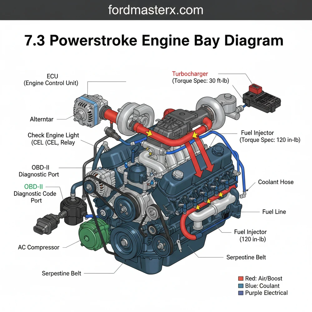
The 7.3 powerstroke engine bay diagram is a visual representation of one of the most durable diesel powerplants ever manufactured. At its core, the diagram highlights the “valley,” the central recessed area between the cylinder heads where several high-maintenance components reside. Centrally located in this valley is the fuel filter housing (often called the fuel bowl) and the High-Pressure Oil Pump (HPOP). The diagram also illustrates the massive turbocharger positioned toward the rear of the engine, tucked near the firewall. Unlike modern engines that rely on a complex timing chain, the 7.3 uses a heavy-duty gear-driven system, though it is often searched for in the context of timing synchronization. The accessory drive at the front of the engine shows the routing for the accessory belt, which powers the alternator, power steering pump, and water pump.
The 7.3 Powerstroke is an HEUI (Hydraulic Electronic Unit Injection) engine. This means it uses highly pressurized engine oil to fire the fuel injectors. When looking at your diagram, the oil system is just as critical as the fuel system for combustion to occur.
(The visual diagram displays the top-down view of the 7.3L engine. Labels include: 1. Fuel Bowl, 2. HPOP Reservoir, 3. Glow Plug Relay, 4. Turbocharger, 5. Intake Plenums, 6. Air Filter Box, 7. Alternator, 8. Degas Bottle/Coolant Reservoir, 9. IDM (typically fender-mounted), 10. Engine Control Unit ECU path).
To effectively use the 7.3 powerstroke engine bay diagram for repairs or inspections, follow this systematic approach to identification and interpretation.
1. Orient Yourself with the Cooling System
Start at the front passenger side. Locate the large translucent tank known as the degas bottle. This is your primary coolant reservoir. From here, you can trace the coolant flow through the upper radiator hose toward the thermostat housing located on the top-center of the water pump. Understanding this flow is vital for cooling system flushes or replacing the thermostat.
2. Identify the High-Pressure Oil System
Look directly behind the cooling fan toward the top of the engine. You will see a rectangular cast-iron reservoir. This is the HPOP reservoir. Below this sits the High-Pressure Oil Pump itself. This system is responsible for the injection pressure that drives the engine. If your diagram shows a leak in the “valley,” the HPOP or its associated lines are the most likely culprits.
3. Locate the Fuel Delivery Components
Directly behind the HPOP reservoir is the fuel bowl. This is a cylindrical housing with a black plastic or metal lid. This is where you change your fuel filter. Following the lines from the fuel bowl will show you how fuel is distributed to the cylinder heads. Note the fuel pressure regulator on the side of the bowl, which is a common point for spring upgrades.
4. Find the Electrical Control Modules
The Engine Control Unit (ECU) is the “brain” of the truck, typically located through the firewall on the driver’s side. However, the 7.3 also utilizes an Injector Driver Module (IDM), usually found mounted on the driver’s side inner fender well. The diagram shows the wiring harness connecting these to the glow plug relay—the large solenoid sitting on top of the engine near the passenger side valve cover.
5. Trace the Accessory Belt Path
The accessory belt drives all your critical peripherals. Check the diagram for the routing path around the pulleys. This is crucial if your belt snaps or if you are replacing the tensioner. Ensure the belt is properly seated in the grooves of the crank pulley, alternator, and A/C compressor to avoid premature wear.
6. Map the Air Intake and Turbocharger
Follow the large plastic ducting from the air filter box (front driver side) to the turbocharger inlet at the rear. The turbo sits on a “pedestal” which is another common leak point for oil. The exhaust gas drives the turbine, while the compressor side pushes fresh air through the intake plenums into the heads.
Always disconnect the batteries before working near the glow plug relay or the IDM. The IDM can hold high voltage even when the engine is off, posing a significant shock risk during maintenance.
When problems arise, the 7.3 powerstroke engine bay diagram serves as your primary diagnostic tool. One of the most common issues is a “no-start” or “hard-start” condition. By referencing the diagram, you can quickly locate the Camshaft Position Sensor (CPS) located on the front of the engine near the harmonic balancer. Another frequent issue involves the check engine light. While the engine is pre-CAN bus, it still utilizes an OBD-II port located under the dashboard on the passenger side or center. By plugging in a compatible scanner, you can pull a diagnostic code that points to specific areas on your diagram, such as the IPR (Injection Pressure Regulator) or the ICP (Injection Control Pressure) sensor.
- ✓ Check the “valley” for standing oil or fuel, which indicates HPOP or fuel bowl seal failure.
- ✓ Inspect the accessory belt for fraying or glazing, as a failure here results in a loss of power steering and brakes (hydroboost system).
- ✓ Monitor the coolant flow for signs of cavitation or “oil-in-coolant” which may suggest oil cooler O-ring failure.
Maintaining a 7.3 Powerstroke requires adherence to specific torque spec standards to prevent leaks in the high-vibration diesel environment. For instance, the fuel bowl lid should be tightened to approximately 25 ft-lbs, while the HPOP mounting bolts require precise tension to ensure the gear drive remains aligned. Always use high-quality, OEM-spec sensors (Motorcraft or International) because the ECU is notoriously sensitive to the voltage tolerances of aftermarket electronics.
Keep a printed copy of the accessory belt routing and a spare CPS in your glove box. These are the two most common “roadside” failures that can be fixed in minutes if you have the parts and the diagram handy.
Regular maintenance of the cooling system is also vital. The 7.3 requires a Supplemental Coolant Additive (SCA) to prevent liner pitting unless you have switched to an ELC (Extended Life Coolant). Use your engine bay diagram to locate the block drains if you are performing a full system flush. Finally, always keep an eye on your OBD-II data logs. Monitoring “ICP Pressure” and “IPR Duty Cycle” while driving can tell you more about the health of your engine than a visual inspection ever could. By combining the visual data from a 7.3 powerstroke engine bay diagram with digital diagnostic tools, you ensure your truck remains on the road for hundreds of thousands of miles to come. In conclusion, treat the diagram as a living document of your truck’s health, and you will find that even the most complex repairs become manageable tasks.
Step-by-Step Guide to Understanding the 7.3 Powerstroke Engine Bay Diagram: Identification Guide
Identify – Start with identifying the main air intake, battery layout, and alternator positions.
Locate – Locate the central fuel filter housing and the high-pressure oil pump (HPOP) reservoir.
Understand – Understand how the wiring harness connects the ECU to the fuel injectors and valve covers.
Apply – Apply the correct torque spec when tightening sensor housings or fuel bowl components to prevent leaks.
Verify – Verify that the ECU signal is consistent via an OBD-II scanner after a check engine light occurs.
Complete – Complete the inspection by checking for fluid leaks around the turbocharger and pedestal area.
Frequently Asked Questions
Where is the ICP sensor located?
The Injector Control Pressure (ICP) sensor is located on the driver’s side cylinder head, near the front of the engine. It is easily accessible on the top of the oil rail. Mechanics often look here first if the engine is running rough or showing poor idle quality due to oil contamination.
What does the engine bay diagram show?
This 7.3 powerstroke engine bay diagram illustrates the layout of the high-pressure oil system, fuel delivery, and electrical sensors. It helps you navigate the engine to find the OBD-II link or ECU components, making it easier to pinpoint the source of a specific diagnostic code during repair sessions.
How many connections does the GPCM have?
The Glow Plug Control Module (GPCM) typically features two large electrical connectors. One harness connects directly to the glow plugs via the valve cover gaskets, while the other links to the engine’s main wiring harness. Ensuring these connections are tight and corrosion-free is vital for reliable cold starts.
What are the symptoms of a bad CPS?
A failing Camshaft Position Sensor (CPS) often causes sudden engine stalling while driving or a complete no-start condition. If your tachometer doesn’t move while cranking, the CPS is likely the culprit. Checking for a diagnostic code related to timing signals will confirm if this sensor requires immediate replacement.
Can I replace the fuel bowl myself?
Most components shown in the engine bay diagram are DIY-friendly. Basic tasks like replacing the fuel filter, ICP sensor, or CPS are straightforward with common hand tools. However, high-pressure oil system repairs require extreme cleanliness and attention to detail to prevent debris from entering the sensitive fuel injectors.
What tools do I need for basic repairs?
Standard repairs require a set of metric sockets, extensions, and a high-quality torque wrench. Always follow the specific torque spec for sensors and bolts to prevent leaks or stripped threads. You will also need an OBD-II scanner to clear any persistent check engine light warnings after your repairs.


