6.7 Powerstroke PCM Wiring Diagram: Easy Setup Guide
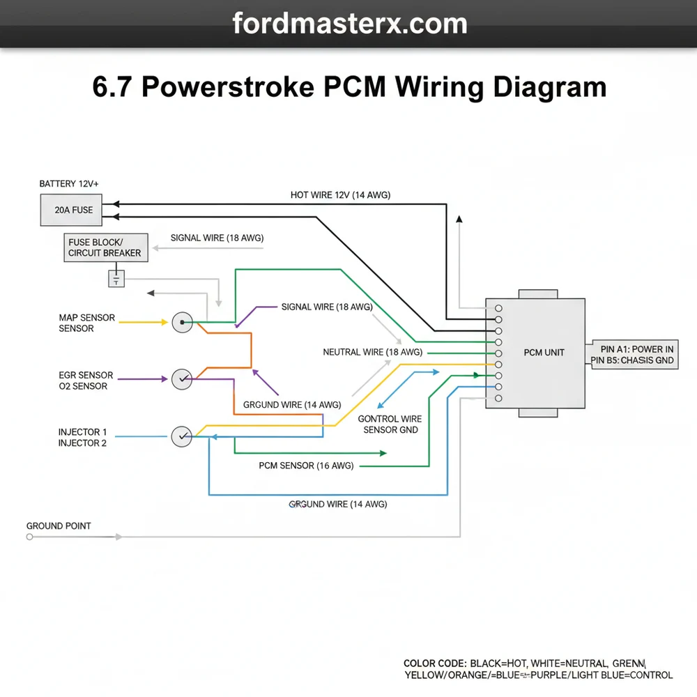
The 6.7 Powerstroke PCM wiring diagram identifies the complex electrical paths connecting the engine sensors to the control module. It highlights how the hot wire supplies power through the common terminal, while every ground wire maintains circuit stability. Use it to trace traveler wire signals between the PCM and the transmission.
📌 Key Takeaways
- The PCM acts as the brain for fuel injection and emissions systems
- Identify the three main high-density connectors to isolate circuits
- Always verify ground integrity to prevent intermittent communication errors
- Use the diagram to trace CAN bus signals between the PCM and TCM
- Essential for diagnosing ‘Crank No Start’ or ‘Limp Mode’ conditions
The 6.7-liter Powerstroke diesel engine, introduced by Ford in 2011, represents a significant leap in electronic engine management. At the heart of this complex system is the Powertrain Control Module (PCM), often referred to as the “brain” of the truck. For the DIY enthusiast, understanding the 6.7 Powerstroke PCM wiring diagram is not just about fixing a broken wire; it is about gaining the ability to diagnose sophisticated performance issues, install aftermarket equipment, or perform necessary repairs without the steep costs of a dealership. The PCM manages everything from fuel injection timing and turbocharger vane position to exhaust after-treatment cycles, making its wiring harness the central nervous system of the vehicle.
Navigating the electrical architecture of a modern Super Duty can be intimidating. With hundreds of wires exiting the PCM and snaking through the engine bay, a methodical approach is required. This guide provides a detailed breakdown of the 6.7 Powerstroke PCM wiring structure, focusing on the common configurations found in the 2011–2022 models. Whether you are chasing a phantom sensor code or pin-testing a circuit for continuity, this technical overview will serve as your roadmap through the intricate landscape of Ford’s diesel electronics.
Main Components and System Features
The PCM on a 6.7 Powerstroke is typically located on the driver’s side of the engine compartment, mounted directly to the firewall. It is encased in a rugged aluminum housing designed to dissipate heat and protect the internal circuitry from electromagnetic interference. The module is connected to the rest of the truck through three primary high-density connectors, often labeled in technical manuals as C1282A, C1282B, and C1282C (though nomenclature may vary slightly by model year).
- Connector 1 (C1282A): Generally focuses on vehicle-wide communications and power. This includes the high-speed CAN (Controller Area Network) bus lines, ignition switch inputs, and battery power leads.
- Connector 2 (C1282B): Primarily handles engine-specific sensors. You will find the wiring for the Crankshaft Position (CKP) sensor, Camshaft Position (CMP) sensor, and various temperature and pressure sensors here.
- Connector 3 (C1282C): Dedicated largely to actuators and injectors. This connector houses the high-voltage lines required to fire the Piezo-electric fuel injectors and the control circuits for the Variable Geometry Turbocharger (VGT) actuator.
One of the most critical features of the 6.7 wiring system is the 5-Volt Reference Circuit (VREF). The PCM sends a steady 5V signal to various sensors (like the MAP or EBP sensors). If this circuit is shorted to ground anywhere in the harness, the PCM may shut down or trigger multiple unrelated sensor codes, making the wiring diagram essential for isolating the fault.
How to Use and Read the Wiring Diagram

Reading a Ford wiring diagram requires an understanding of their specific coding language. Unlike basic DC circuits, these diagrams use a combination of alphanumeric codes to identify wire color, gauge, and circuit function. When looking at a 6.7 Powerstroke schematic, you will see labels like “VT-GN” or “BN-WH.”
- Wire Colors: The first part is the base color, and the second is the stripe. For example, VT-GN means a Violet wire with a Green stripe. Common abbreviations include:
- BK: Black
- BU: Blue
- GN: Green
- GY: Grey
- OG: Orange
- PK: Pink
- RD: Red
- VT: Violet
- WH: White
- YE: Yellow
- Pin Numbering: On the diagram, each connector is represented by a grid. The pins are numbered. When looking at the face of the connector (unplugged), the numbering usually goes from top-left to bottom-right, but always verify with the small embossed numbers on the plastic connector housing itself.
- Splices and Grounds: Splices are indicated by a dot or a “S” prefix (e.g., S102). Grounds are indicated by a “G” prefix (e.g., G101). On the 6.7 Powerstroke, the main PCM ground is typically located on the driver’s side fender or firewall near the module.
To effectively use the diagram, start with the component you are troubleshooting. If your “Engine Oil Temperature” sensor is failing, find the sensor on the diagram, trace the two wires back to the PCM connector, and note the pin numbers. This allows you to perform a “continuity test” from the sensor plug to the PCM plug to ensure the wire isn’t broken inside the loom.
Pro Tips for DIY Wiring Work

Working on the 6.7 Powerstroke wiring harness requires precision. These are not the heavy-gauge wires found in older trucks; they are thin, signal-grade wires that are easily damaged.
- Use a Digital Multimeter (DMM): Ensure your DMM has high input impedance (at least 10 Megohms) to avoid drawing too much current from the PCM circuits, which can fry internal components.
- Document Everything: Before unplugging the large PCM connectors, take a photo. Note the routing of the plastic channels. The harness is designed to sit in a specific way to avoid heat from the EGR cooler and the turbocharger.
- Dielectric Grease: Use a very small amount of dielectric grease on the weather seals of the connectors, but avoid slathering it on the actual pins. Too much grease can cause “hydro-locking” of the connector, preventing it from seating fully and causing intermittent communication errors.
- Heat Protection: The 6.7 engine bay gets extremely hot. If you have to repair a wire, use heat-shrink tubing with an internal adhesive (marine grade) and re-wrap the section with high-temp wire loom or Tesa tape.
Troubleshooting Common PCM Wiring Issues
Even with a perfect diagram, troubleshooting requires a logical process. On the 6.7 Powerstroke, there are several “hot spots” where wiring issues commonly occur.
1. Harness Chafing
One of the most frequent causes of “Communication Lost” codes (U0100) or erratic sensor readings is wire chafing. The harness that runs over the driver’s side valve cover and near the steering column is prone to vibration. Over time, the plastic loom wears through, and the wires rub against the metal engine components. Inspect these areas visually before assuming the PCM has failed.
2. The “VREF” Short
If your truck won’t start and you have a handful of different sensor codes (EBP, MAP, Cooling Fan), you likely have a short in the 5V reference circuit. Use your wiring diagram to identify all sensors sharing the VREF line. Unplug them one by one. If the truck starts or the 5V signal returns when a specific sensor is unplugged, that sensor or its specific wire lead is the culprit.
3. Connector Corrosion
Because the PCM is located near the cowl, water can occasionally migrate down the harness if the weather stripping is damaged. If you see white or green oxidation on the PCM pins, clean them with electronic contact cleaner and a soft brush. Ensure the locking tabs on the connectors “click” into place; a loose PCM connector can cause the engine to shut off while driving.
4. Testing for Power and Ground
Before replacing a PCM, always verify it is actually getting power. Use the wiring diagram to find the “B+” (Battery Constant) and “Switched Ignition” pins. Check these with a test light or multimeter. Similarly, check the ground pins (usually Black or Black/Yellow). A PCM cannot function without a clean path to the negative battery terminal. If the ground has more than 0.1 ohms of resistance, you have a bad connection that needs cleaning.
By combining a high-quality wiring diagram with these diagnostic techniques, you can master the electrical system of your 6.7 Powerstroke. Remember that patience is key—diesel electrical systems are rarely “broken”; they are usually just “interrupted” by physical wear or environmental factors.
Step-by-Step Guide to Understanding the 6.7 Powerstroke Pcm Wiring Diagram: Easy Setup Guide
Identify the specific PCM connector (C1232B, E, or T) relevant to the sensor or circuit you are currently troubleshooting.
Locate the common terminal points on the diagram where multiple sensors share a 5-volt reference or a signal return line.
Understand how each hot wire delivers fused battery power to the module to ensure the computer is actually turning on.
Connect the multimeter probes to the appropriate ground wire pins to verify that the PCM has a clean path to the chassis.
Verify that every traveler wire used for communication between the PCM and the transmission control module has zero resistance and no shorts.
Complete the process by checking the neutral wire reference or return path for any sensors that are reporting out-of-range voltage codes.
Frequently Asked Questions
Where is the 6.7 Powerstroke PCM located?
The Powertrain Control Module is typically located within the engine compartment on the driver’s side firewall. It is protected by a heavy-duty plastic or metal housing and is connected to the vehicle harness via three large, multi-pin connectors that distribute signals to the entire engine and transmission system.
What does the 6.7 Powerstroke PCM wiring diagram show?
This diagram illustrates the point-to-point connections for every sensor and actuator on the engine. It details the hot wire power distribution from the battery, the common terminal points for shared sensors, and the specific pinout locations for critical inputs like the high-pressure fuel pump and injector drivers.
How many connections does the 6.7 Powerstroke PCM have?
The PCM features three primary high-density connectors, often labeled C1232B, C1232E, and C1232T. Each connector contains dozens of pins—sometimes over 70 per plug—totaling hundreds of possible connection points for data, power, and ground, which are all mapped out in a professional-grade technical wiring diagram for the vehicle.
What are the symptoms of a bad 6.7 Powerstroke PCM?
Common symptoms include a ‘crank but no start’ condition, sudden engine stalling, or the truck entering limp mode with reduced power. You may also see erratic shifting, multiple sensor fault codes appearing simultaneously, or a complete loss of communication between your OBDII scanner and the vehicle’s internal network.
Can I replace the 6.7 Powerstroke PCM myself?
While physically removing the module is straightforward, replacing a 6.7 Powerstroke PCM is a complex task. The new unit must be flashed with the correct VIN and latest software calibration using Ford-specific diagnostic tools. Without professional programming, the truck will likely fail to start due to anti-theft security protocols.
What tools do I need for PCM wiring diagnostics?
To effectively use the wiring diagram, you need a high-quality digital multimeter for checking voltage and continuity. A back-probing kit is essential to test circuits while connectors remain plugged in. Additionally, an OBDII scanner with live data capabilities helps verify if the PCM is receiving the correct signals.


