6.4 Powerstroke Transmission Cooler Lines Diagram Guide
The 6.4 Powerstroke transmission cooler lines diagram illustrates the routing from the 5R110W transmission to the external cooler and radiator. It shows the supply line exiting the front passenger side of the transmission, traveling to the secondary cooling system, and returning via the rear fitting to ensure proper thermal management for heavy towing.
📌 Key Takeaways
- Main purpose: Visualizing the fluid flow between the 5R110W transmission and the cooling assembly.
- Most important component: The external bypass valve and quick-connect fittings.
- Safety consideration: Always check fluid levels after installation to prevent transmission slippage.
- Practical application: Use the diagram to identify leak points at the common high-wear junctions.
- When to use: Use during line replacement or when upgrading to an aftermarket high-flow cooler.
Understanding the intricacies of the 6.4 Powerstroke transmission cooler lines diagram is a critical skill for any owner or technician looking to maintain the longevity of the 5R110W TorqShift transmission. These heavy-duty trucks generate immense heat, especially when towing or hauling, and the transmission cooling system is the primary defense against catastrophic internal failure. Because the 6.4L engine bay is notoriously cramped, identifying the specific routing of these lines can be a daunting task without a clear visual reference. This guide will provide you with a comprehensive breakdown of the line routing, the function of the bypass valves, and how to use a diagram to diagnose flow restrictions or leaks effectively. By the end of this article, you will have a professional-grade understanding of how fluid moves from your transmission to the cooling stack and back.
The 6.4 Powerstroke utilizes a dual-cooling method involving both a liquid-to-liquid heat exchanger and a large air-to-liquid cooler located behind the grille. Understanding the flow direction is essential for flushing the system or installing an aftermarket bypass.
Understanding the 6.4 Powerstroke Transmission Cooler Lines Diagram
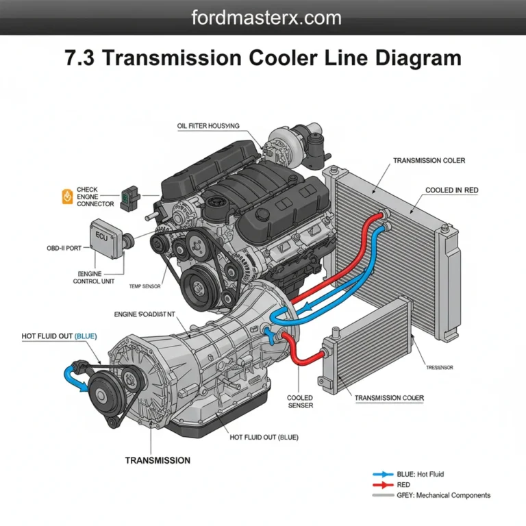
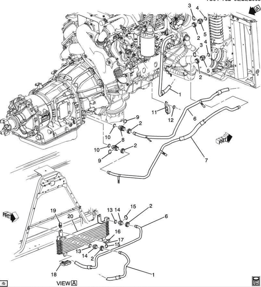
The transmission cooling system on a 6.4L Powerstroke is significantly more complex than its predecessors. When looking at a 6.4 powerstroke transmission cooler lines diagram, you will notice two main lines exiting the passenger side of the 5R110W transmission case. These are typically referred to as the pressure (discharge) line and the return line. The discharge line originates from the front fitting on the transmission case, carrying hot fluid toward the front of the vehicle.
The fluid first encounters a remote-mounted oil filter assembly, which is unique to this platform. From there, the lines route forward toward the radiator assembly. A key element in the diagram is the transmission fluid bypass valve. This thermal element remains closed when the fluid is cold, allowing it to reach operating temperature faster by bypassing the front coolers. Once the fluid reaches approximately 165 degrees Fahrenheit, the valve opens, directing fluid into the cooling stack.
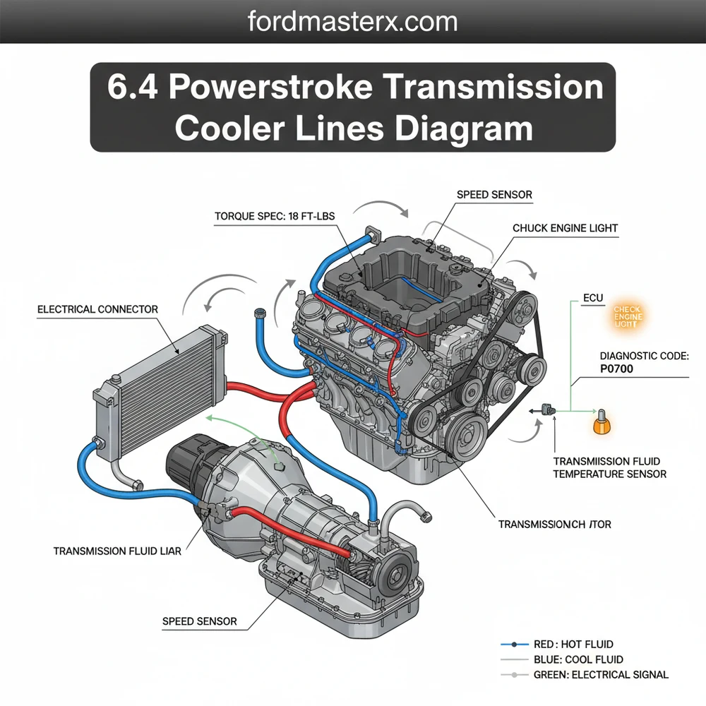
The cooling stack itself consists of the primary radiator (where coolant flow assists in heat exchange) and the dedicated transmission cooler. The lines are constructed from a combination of rigid steel tubing to withstand high pressure and flexible rubber sections near the engine to account for vibration and torque-induced movement. On most diagrams, the “out” flow is color-coded red or marked with an arrow pointing away from the transmission, while the “return” flow is blue or marked with an arrow returning to the rear fitting on the transmission case.
(Visual Description: A detailed technical schematic showing the 5R110W transmission with two lines exiting the passenger side. Line A (Hot) leads to a remote filter housing, then to the bottom of the radiator. Line B (Cold) returns from the top of the air-to-liquid cooler back to the rear transmission port. Labels indicate the thermal bypass valve and the intersection with the accessory belt area.)
Step-By-Step Guide to Identifying and Replacing Lines
Interpreting a 6.4 powerstroke transmission cooler lines diagram and applying it to physical repairs requires a methodical approach. Whether you are searching for a leak or performing a full system flush, follow these steps to ensure the job is done correctly.
- ✓ Step 1: Locate the Transmission Ports – Begin at the passenger side of the transmission. The forward-most fitting is the hot output. The rearward fitting is the cooled return. Verify their condition for any signs of “weeping” at the threads.
- ✓ Step 2: Trace the External Filter Path – Follow the hot line to the passenger-side frame rail. You will find the external roll-style filter. Use the diagram to confirm that the lines are not crossed at this junction, as improper flow will bypass the filter entirely.
- ✓ Step 3: Inspect the Thermal Bypass – Move forward toward the engine. Locate the bypass block. This is a frequent failure point. Check for corrosion where the steel lines meet the aluminum block.
- ✓ Step 4: Navigate the Front Stack – The lines will pass near the bottom of the fan shroud. Be careful here, as the lines route close to the accessory belt and pulleys. Ensure all factory clips are in place to prevent the lines from rubbing against moving parts.
- ✓ Step 5: Disconnect with Precision – If replacing a line, use a dedicated 1/2-inch or 5/8-inch quick-disconnect tool. These lines do not use standard flare nuts; using the wrong tool will damage the internal spring clips.
- ✓ Step 6: Final Torque and Fluid Check – Once the new lines are seated (you should hear a distinct “click”), secure the mounting brackets to the specific torque spec of 18-22 lb-ft. Refill the transmission with Mercon SP or LV fluid and check for leaks while the engine is idling.
Never attempt to service transmission lines while the engine is hot. The 6.4 Powerstroke operates at high pressures, and the fluid can cause severe burns. Additionally, ensure the vehicle is securely on jack stands, as you will be working directly under the heavy transmission housing.
Common Issues and Troubleshooting

The most common issue users face with the 6.4 Powerstroke cooling system is a restricted flow caused by a sticking thermal bypass valve or a clogged external filter. If your transmission temperatures are climbing but the front cooler remains cold to the touch, the bypass valve is likely failed in the “closed” position.
Another frequent problem is the “Check Engine Light” appearing on the dashboard. Using an OBD-II scanner, you might find a diagnostic code such as P0711 (Transmission Fluid Temperature Sensor Range/Performance). This data is processed by the ECU to manage shift points. If the ECU detects that the fluid is not reaching the correct temperature or is overheating too quickly, it may put the truck into a “limp mode” to protect the internal clutches.
The diagram helps troubleshoot these issues by identifying the “test points” for flow. For example, by safely disconnecting the return line at the rear of the transmission and briefly running the engine, you can verify if the pump is successfully pushing fluid through the entire cooling circuit. If flow is weak, you can backtrack through the diagram—checking the filter, then the bypass, then the cooler—to isolate the blockage.
Tips and Best Practices for Maintenance
Maintaining the transmission lines on a 6.4 Powerstroke involves more than just looking for leaks. Because this engine is known for its complex front-end accessory drive, the vibration can cause the metal lines to fatigue over time.
Whenever you are performing a service that requires removing the radiator or working near the timing assembly, take the time to inspect the transmission line plastic clips. These clips often become brittle from heat and snap, allowing the lines to vibrate and eventually crack.
When replacing components, always prioritize high-quality OEM or heavy-duty aftermarket lines. The 6.4L produces significant torque, which translates into chassis flex. Substandard lines may not have the proper reinforcement at the crimp points where the rubber meets the steel.
Additionally, keep an eye on the coolant flow in your primary radiator. Since the transmission fluid passes through a heat exchanger submerged in the radiator, an engine cooling issue can indirectly cause transmission overheating. Ensure your coolant is clean and the pH levels are balanced to prevent internal corrosion of the heat exchanger, which could lead to “pink milkshake” syndrome—the catastrophic mixing of transmission fluid and engine coolant.
Finally, always use the correct diagnostic tools. An OBD-II monitor that provides real-time digital readouts of the transmission fluid temperature is far more accurate than the “dummy gauge” on the factory instrument cluster. If you see temperatures consistently exceeding 220 degrees Fahrenheit during normal driving, consult your 6.4 powerstroke transmission cooler lines diagram and check for obstructions in the air-to-liquid cooler fins, often caused by road debris or bugs.
By following the routing shown in a proper 6.4 powerstroke transmission cooler lines diagram and adhering to the torque specs and maintenance intervals outlined here, you can ensure your TorqShift transmission remains cool and functional for hundreds of thousands of miles. Proper identification of the ECU-monitored sensors and the physical layout of the lines is the best way to prevent unexpected downtime and expensive shop bills.
Step-by-Step Guide to Understanding the 6.4 Powerstroke Transmission Cooler Lines Diagram Guide
Identify – Start by identifying the supply and return ports on the passenger side of the transmission case.
Locate – Locate the routing path of the lines as they travel forward along the engine and frame rail.
Understand – Understand how the quick-connect fittings lock onto the transmission cooler assembly to prevent leaks.
Connect – Connect the new lines while ensuring they are secured away from moving engine components or exhaust heat.
Verify – Verify that all fittings are seated and tightened to the manufacturer’s recommended torque spec.
Complete – Complete the process by checking fluid levels and using an OBD-II tool to scan the ECU for faults.
Frequently Asked Questions
Where are the transmission cooler lines located?
The lines originate on the passenger side of the 5R110W transmission housing. They route forward along the engine block, passing the oil pan, and connect to the transmission cooler located in front of the radiator assembly behind the grille for maximum airflow and cooling efficiency during heavy-duty operation.
What does the transmission cooler lines diagram show?
This diagram illustrates the high-pressure supply and return paths for transmission fluid. It highlights the connections between the transmission case, the external cooler, and any integrated radiator heat exchangers, helping technicians trace fluid movement and identify where potential blockages or leaks may occur in the high-pressure system.
How many connections do the 6.4 Powerstroke cooler lines have?
These lines typically feature four main connection points: two at the transmission housing (supply and return) and two at the cooler assembly. They often utilize quick-connect fittings that require specific tools for removal without damaging the internal seals or the aluminum tubing during a standard maintenance procedure.
What are the symptoms of bad transmission cooler lines?
Common symptoms include visible red fluid leaking under the truck, transmission overheating, and erratic shifting. If a leak causes low fluid, the ECU may trigger a check engine light or store a specific diagnostic code in the OBD-II system related to transmission slip or fluid temperature irregularities.
Can I replace these cooler lines myself?
Yes, owners can replace these lines with basic hand tools and a quick-disconnect set. However, it requires significant space under the vehicle and careful attention to the torque spec for any threaded fittings to prevent stripping the soft aluminum ports on the transmission housing or the cooler.
What tools do I need for this task?
You will need a set of line wrenches, a drain pan for spilled fluid, and specialized quick-disconnect tools for the 1/2-inch fittings. An OBD-II scanner is also helpful to clear any diagnostic code or check engine light issues after the fluid levels are topped off and verified.