6.0 Powerstroke Oil Flow Diagram: System Guide
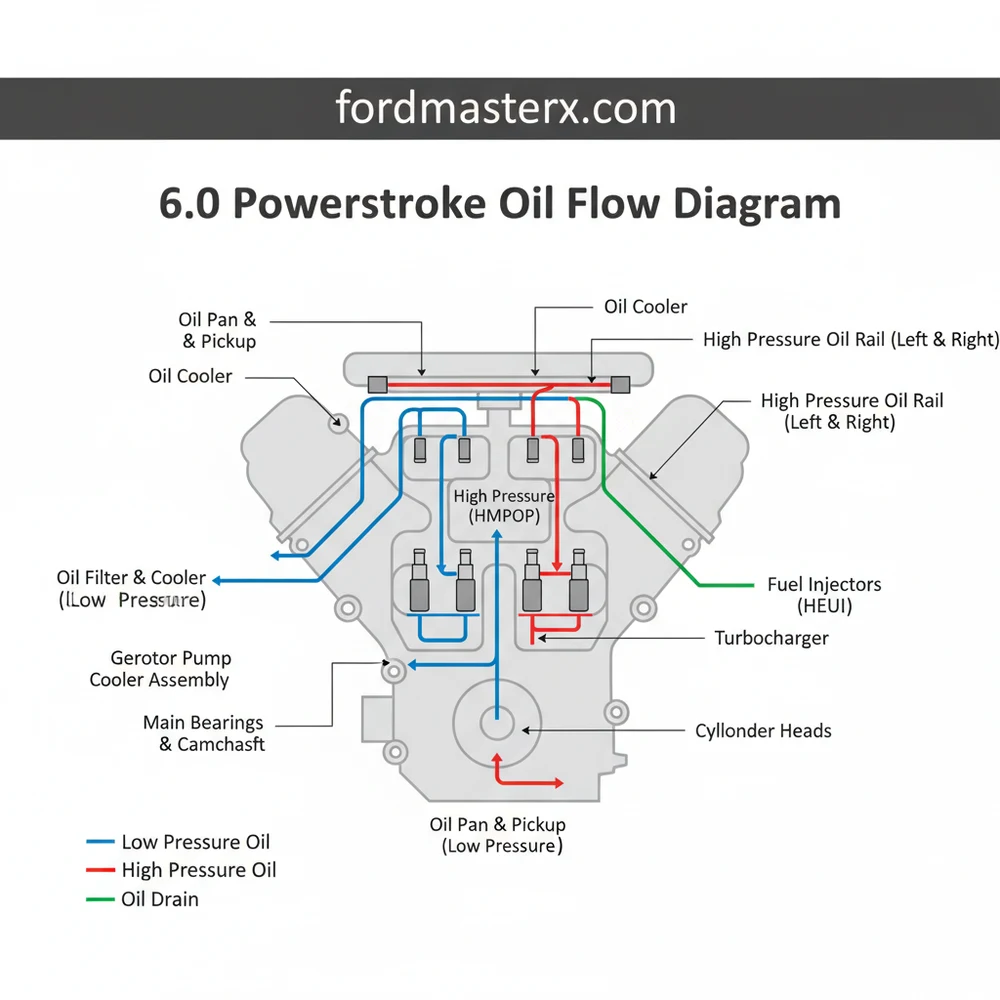
The 6.0 Powerstroke oil flow diagram tracks oil from the pan through the gerotor pump to the oil cooler and filter. It then splits into the low-pressure system for lubrication and the high-pressure system for fuel injection. Understanding this structure helps identify pressure drops and cooling failures in the lubrication configuration.
📌 Key Takeaways
- Maps the dual-path lubrication and high-pressure oil systems.
- The oil cooler is the most critical point for heat exchange.
- Never mix high-pressure and low-pressure components during repair.
- Use the diagram to trace leaks or pressure loss chronologically.
- Essential for diagnosing HPOP or oil cooler efficiency issues.
The 6.0L Powerstroke diesel engine, manufactured by Navistar for Ford between 2003 and 2007, is renowned for its complexity, primarily due to its sophisticated oiling system. Unlike traditional gasoline engines where oil is strictly for lubrication, the 6.0L uses oil as a hydraulic fluid to fire the fuel injectors through a system called HEUI (Hydraulic Electronic Unit Injection). Understanding the 6.0 Powerstroke oil flow diagram is not just an academic exercise; for the DIY enthusiast, it is a prerequisite for diagnosing “no-start” conditions, low power, or overheating issues. The system is split into two distinct yet interdependent circuits: the Low-Pressure Oil System and the High-Pressure Oil System.
Main Components and Features
To navigate an oil flow diagram effectively, you must first identify the primary hardware located within the engine block and valley. The system begins at the bottom and works its way to the top of the engine.
- Oil Pan and Pickup Tube: The reservoir holds 15 quarts of 15W-40 (standard) oil. The pickup tube features a screen to prevent large debris from entering the pump.
- Low-Pressure Oil Pump (LPOP): Located behind the harmonic balancer on the front of the crankshaft. It is a gerotor-style pump that draws oil from the pan and sends it to the oil cooler and filter.
- Oil Cooler and Filter Housing: Located in the “valley” of the engine. The oil cooler is a plate-style heat exchanger where engine coolant absorbs heat from the oil. The filter housing sits on top, utilizing a cartridge-style filter (FL-2016).
- High-Pressure Oil Pump (HPOP) Reservoir: A small cast-iron reservoir located under the oil cooler housing. It holds a reserve of filtered oil to ensure the HPOP never runs dry during startup.
- High-Pressure Oil Pump (HPOP): Located at the rear of the engine valley. In 2003-2004.5 models, this is a swash-plate style pump; in 2005-2007 models, it is a more robust V-style gear pump.
- IPR (Injection Pressure Regulator) Valve: An electromagnetic actuator screwed into the HPOP (or the cover). It controls the oil pressure by dumping excess oil back into the crankcase.
- ICP (Injection Control Pressure) Sensor: This sensor monitors the actual pressure in the high-pressure system. On early models (2003), it is located on the HPOP cover; on later models, it is on the passenger side valve cover or oil rail.
- Stand Pipes and Dummy Plugs: These deliver high-pressure oil from the branch tubes to the oil rails located under the valve covers.
How to Use and Read the Flow Diagram

Reading a 6.0 oil flow diagram requires tracing the path of the oil as it changes from a simple lubricant to a high-pressure hydraulic fluid. When looking at a diagram, follow this specific sequence:
1. The Low-Pressure Side (Lube Circuit)
Trace the line from the Oil Pan to the LPOP. From the LPOP, the oil travels through a passage in the front cover to the Oil Cooler. It enters the cooler, passes through the internal plates, and then moves upward into the Oil Filter Housing. After being filtered, the oil splits: one path goes to lubricate the main bearings, camshaft, and turbocharger (usually around 40-70 PSI), while the other path fills the HPOP Reservoir.
2. The High-Pressure Side (Injection Circuit)
This is where the diagram becomes critical for DIYers. Look for the line leaving the HPOP reservoir and entering the HPOP. The pump compresses the oil. From the pump, the oil travels through Branch Tubes. In 2005+ models, look for the “Snap-To-Connect” (STC) fitting on the pump outlet—a common failure point. The oil then flows through the Stand Pipes into the High-Pressure Oil Rails. Finally, the diagram will show lines branching into each of the eight Fuel Injectors. The injectors use this pressure to squeeze the fuel intensifier piston.
Maintenance and DIY Tips

Maintaining the oil flow is the single most important factor in 6.0L longevity. Because the oil is sheared at high pressures (up to 4,000 PSI), it breaks down faster than in a standard engine.
- Use OEM Filters Only: The 6.0L oil filter cap has a built-in bypass valve. Aftermarket filters (like those from Wix or Fram with integrated caps) are often the wrong height, which can lead to unfiltered oil bypassing the system or the reservoir draining back, causing hard starts. Use the Motorcraft FL-2016.
- Monitor the “Delta”: Use an OBD-II monitor (like Edge Insight or Forscan) to check the difference between Oil Temperature (EOT) and Coolant Temperature (ECT). If the EOT is more than 15 degrees higher than the ECT at highway speeds, your oil cooler is clogging, which restricts flow to the HPOP.
- The 36mm Socket: You will need a 36mm low-profile socket to remove the oil filter cap. Do not use pliers, as the plastic cap is prone to cracking.
- Wire Colors for Diagnostics: If troubleshooting the ICP sensor, the wiring typically follows this pattern: Brown/White (5V Reference), Gray/Red (Signal Ground), and Blue/Light Green (Signal to PCM). If you see oil in the connector of the ICP sensor, it has failed internally and must be replaced.
Troubleshooting Common Oil Flow Issues
If your 6.0 Powerstroke cranks but won’t start, the oil flow diagram is your roadmap to the solution. The engine requires a minimum of 500 PSI of high-pressure oil to fire the injectors.
Low-Pressure Failures
If the dash “Oil Pressure” gauge (which is actually a switch) doesn’t move while cranking, the LPOP may not be primed, or the regulator is stuck. Check the oil filter housing; if it doesn’t fill with oil while cranking, your LPOP or the pickup tube is the culprit. Another common issue is the Oil Pressure Regulator (located near the LPOP), which can get stuck open by a piece of debris.
High-Pressure Leaks
If you have low-pressure but the engine won’t start, you likely have a “High-Pressure Oil Leak.”
- 2003-2004 Models: The HPOP itself is a high-failure item. If the ICP reading stays below 500 PSI during cranking, the pump is likely dead.
- 2005-2007 Models: The STC fitting on the HPOP often pops or leaks. Additionally, the O-rings on the Stand Pipes and Dummy Plugs are notorious for leaking when the oil gets hot. A classic symptom is an engine that starts fine when cold but won’t restart once it’s up to operating temperature.
IPR Valve Issues
The IPR valve has a tiny screen on the tip. If debris from a failing oil cooler or LPOP reaches this screen, it can tear or clog. If the screen is sucked in, it indicates the HPOP is trying to pull oil that isn’t there, or the valve is stuck. You can air-test the system by applying 100 PSI of shop air through the ICP sensor port and using a scan tool to close the IPR valve; if you hear air hissing under the valve covers, you’ve found your leak.
By understanding the dual-stage nature of the 6.0L Powerstroke oil flow, you can move from “guessing” to “diagnosing.” Whether it’s ensuring your oil cooler is keeping the “Delta” in check or air-testing the high-pressure rails for a leak, the oil flow diagram is the most powerful tool in your DIY arsenal.
Step-by-Step Guide to Understanding the 6.0 Powerstroke Oil Flow Diagram: System Guide
Identify the oil reservoir and pickup tube within the oil pan structure.
Locate the low-pressure oil pump responsible for initial fluid movement.
Understand how oil moves through the oil cooler and filtration assembly layout.
Connect the flow path from the reservoir to the high-pressure oil pump component.
Verify that oil reaches both the turbocharger and the main engine bearings.
Complete the visual inspection of the high-pressure rails and IPR valve system configuration.
Frequently Asked Questions
Where is the oil cooler located?
Located within the engine valley, the oil cooler is submerged in engine coolant to regulate temperatures. It sits beneath the oil filter housing and is a critical component for preventing high-pressure oil system failure due to clogging or debris buildup within the oil flow path structure.
What does the 6.0 Powerstroke oil flow diagram show?
This diagram illustrates the complex flow of oil from the pick-up tube to the lubrication points and the High-Pressure Oil Pump (HPOP). It highlights how the layout manages both cooling and hydraulic pressure required to fire the fuel injectors throughout the entire engine system configuration.
How many pumps does the oil system have?
The system features two distinct stages: a low-pressure gerotor pump located behind the harmonic balancer and a high-pressure oil pump (HPOP) located in the rear of the engine valley. This configuration ensures the engine remains lubricated while providing the hydraulic force needed for fuel injection processes.
What are the symptoms of a bad oil system?
Common symptoms include hard starts, no-starts when hot, and poor engine performance. If the oil flow is restricted, you may notice high EOT versus ECT deltas, which often indicates a clogged oil cooler component within the system layout, potentially leading to catastrophic engine damage if ignored.
Can I replace the oil cooler myself?
Replacing the oil cooler is a complex DIY task requiring the removal of the intake manifold and turbocharger. While possible for experienced mechanics, it requires precision to ensure the oil and coolant seals are seated correctly within the engine structure to prevent future internal leaks or contamination.
What tools do I need for oil system diagnosis?
You will need a digital monitor to check EOT and ECT deltas, a mechanical oil pressure gauge for testing the low-pressure side, and an IPR air test tool to find leaks within the high-pressure oil system configuration. These tools are essential for identifying failures in the oil path.