Where is the Crankshaft Position Sensor? Ford Location Guide in 2026
The crankshaft position sensor (CKP) operates as the foundational timing authority for modern internal combustion engines. By continuously monitoring the rotational speed and exact mechanical position of the crankshaft via a toothed reluctor wheel, the CKP transmits microsecond-accurate data to the Powertrain Control Module (PCM).
The engine management system relies entirely on this continuous data stream to dictate precise fuel injection sequencing, optimize ignition spark timing, and monitor microscopic fluctuations in rotational velocity to detect cylinder misfires. When this component begins to degrade or fails entirely, the immediate consequences range from erratic idling and severe reductions in fuel economy to a catastrophic “crank-no-start” condition that renders the vehicle inoperable.
This report provides an exhaustive, engine-specific analysis of crankshaft position sensor locations across modern Ford architectures—specifically focusing on the EcoBoost, Coyote, Triton, PowerStroke, and Godzilla platforms. The analysis synthesizes advanced electrical diagnostic protocols, common wiring harness failure points, OEM technical service bulletins (TSBs), and the critical, yet frequently overlooked, sensor relearn procedures required after part replacement.
Where Is The Crankshaft Position Sensor?
A deep-dive technical guide into locating, diagnosing, and replacing the CKP sensor. The unsung hero of your engine’s timing and fuel delivery system.
What is a Crankshaft Position Sensor (CKP)?
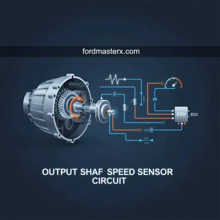
Before tearing into your engine bay, it is critical to understand what the Crankshaft Position Sensor (often abbreviated as CKP or CPS) actually does. The CKP is an electronic device utilized in an internal combustion engine to monitor the position or rotational speed of the crankshaft.
This information is transmitted to the Engine Control Unit (ECU). The ECU uses this highly precise rotational data to control ignition system timing, fuel injection timing, and to monitor for engine misfires. Without a functioning CKP, the ECU is completely blind to engine timing. This is why a total failure usually results in a vehicle that cranks but refuses to start.
Modern vehicles generally utilize one of two sensor types: a magnetic inductive sensor (typically a 2-wire setup that generates an AC voltage) or a Hall-effect sensor (a 3-wire setup that receives a 5V reference and toggles a digital square wave).
Market Distribution of Sensor Technologies
Hall-Effect sensors dominate modern automotive manufacturing due to their digital precision at low RPMs compared to older inductive designs.
Locating the Sensor
The exact location of the crankshaft position sensor varies wildly depending on the vehicle’s make, model, and engine configuration (transverse vs. longitudinal). However, automotive engineers typically place them in one of four primary zones.
Front of Engine (Harmonic Balancer)
The most common location. The sensor is mounted to the lower engine block, pointing directly at a reluctor wheel attached to the harmonic balancer or crankshaft pulley. It is usually visible from under the vehicle, near the serpentine belt path.
Rear of Engine (Bell Housing)
Common on many European models and larger trucks. The sensor is bolted into the transmission bell housing, reading a reluctor ring integrated directly into the engine’s flywheel or flexplate.
Side of Engine Block
Inserted through a machined hole directly into the side of the engine block (often near the oil pan rail). The sensor reads a magnetic wheel mounted directly onto the crankshaft web internal to the crankcase.
Behind the Timing Cover
The most difficult to access. The sensor is mounted on the front of the block but is completely hidden behind the protective timing chain or timing belt cover, reading a sprocket on the front of the crankshaft.
Probability of Sensor Location Across All Vehicle Makes
Symptoms of a Failing CKP Sensor
Frequency of Reported Symptoms
Data aggregated from major automotive diagnostic databases. A “Crank, No Start” condition is the definitive hallmark of total sensor failure.
Diagnostic Warning Signs
Because the ECU relies on the CKP for foundational engine timing, a failing sensor produces dramatic drivability issues. Symptoms often begin intermittently when the engine reaches operating temperature (thermal expansion causes internal sensor wiring to break) and worsen over time.
-
•
Crank, No Start Condition: The starter motor turns the engine over normally, but the engine will not fire. The ECU cuts fuel and spark because it does not know when to fire them.
-
•
Intermittent Stalling: The vehicle runs fine, then suddenly dies while driving, often at a stoplight or when decelerating. It may restart after cooling down for 20 minutes.
-
•
Check Engine Light (OBD2 Codes): The ECU will flag codes spanning from P0335 to P0339. P0335 (Crankshaft Position Sensor ‘A’ Circuit) is the most universally standard code for this failure.
-
•
Engine Misfires & Rough Idle: An erratic signal causes the ECU to miscalculate ignition timing, resulting in a stumbling idle, poor acceleration, and raw fuel smell from the exhaust.
Expert Tip: If your vehicle cranks but won’t start, watch the RPM gauge (tachometer) on your dashboard. If the needle stays perfectly at 0 RPM while cranking, your ECU is likely not receiving a signal from the Crankshaft Position Sensor.
Replacement Economics & Data
Replacing a CKP sensor is generally considered a minor to moderate repair. The bulk of the cost heavily depends on the sensor’s physical location. A sensor mounted externally near the harmonic balancer takes 15 minutes to swap, while one trapped behind a timing cover requires hours of labor.
| Vehicle Class | Parts Cost (Avg) | Labor Cost (Avg) | Total Est. |
|---|---|---|---|
| Economy / Compact | $35 – $65 | $80 – $120 | $115 – $185 |
| Mid-Size Sedan | $50 – $90 | $100 – $150 | $150 – $240 |
| SUVs & Trucks | $60 – $120 | $120 – $200 | $180 – $320 |
| Luxury / European | $100 – $250 | $200 – $450 | $300 – $700+ |
DIY vs. Professional Repair Cost Comparison
DIY replacements save entirely on labor margins. However, accessing sensors located behind the engine block requires specialized tools.
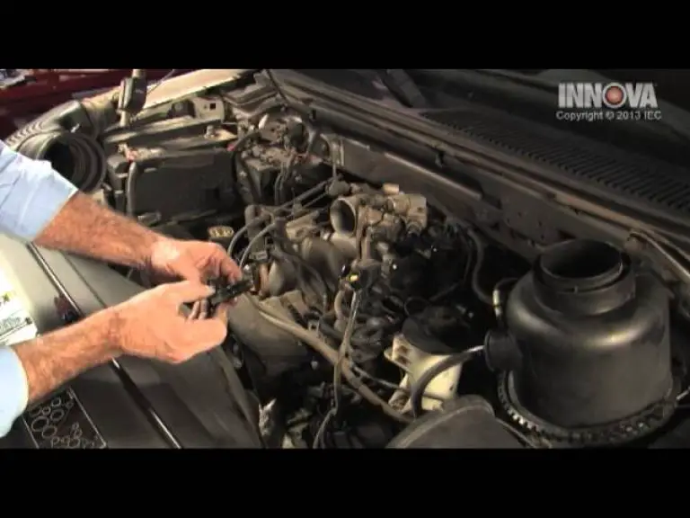
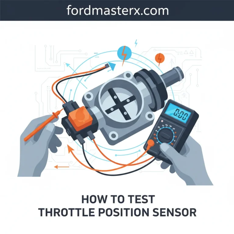
How to Test the Crankshaft Position Sensor
Throwing parts at a vehicle without proper diagnostic testing is a fast way to waste money. A digital multimeter (DMM) is required to verify sensor failure before replacement. The testing methodology depends strictly on whether your vehicle utilizes a 2-wire inductive sensor or a 3-wire Hall-effect sensor.
Testing a 2-Wire (Inductive) Sensor
Inductive sensors generate their own alternating current (AC) voltage by creating a magnetic field that is interrupted by the spinning reluctor wheel.
- Disconnect the electrical pigtail from the sensor.
- Set your digital multimeter to the Ohms (Ω) setting.
- Probe the two terminals on the sensor itself.
- Compare the reading to your factory service manual. Most healthy sensors read between 200 and 1,000 Ohms.
- If the reading is “OL” (Open Loop) or completely zero, the internal coil is broken or shorted, and the sensor is dead.
- For advanced testing, set the multimeter to AC Voltage, probe the wires while someone cranks the engine; you should see a pulsing AC voltage output (0.5V to 2V).
Testing a 3-Wire (Hall-Effect) Sensor
Hall-Effect sensors require external power. They consist of a 5V Reference wire, a Ground wire, and a Signal Return wire.
- Do not disconnect the sensor. You must back-probe the connector while it is plugged in.
- Set the multimeter to DC Volts. Connect the black lead to the negative battery terminal.
- Turn the ignition to the “ON” position (engine off).
- Probe the wiring to find the 5V power feed and the good ground connection.
- Probe the Signal wire. Have a helper manually turn the engine crankshaft using a socket on the harmonic balancer bolt.
- As the reluctor wheel passes the sensor, the voltage on the signal wire should sharply toggle between 0 Volts and 5 Volts. If the voltage remains static, the sensor has failed.
Ford Engine Architecture: Crankshaft Position Sensor Location Matrix
Due to vastly different block designs, forced induction plumbing, cooling jackets, and transmission pairings, Ford powertrain engineers have positioned the CKP in wildly varying locations depending on the engine family. Locating the sensor requires an understanding of the specific engine architecture, as placement ranges from easily accessible front-block mounts to incredibly complex rear-block installations requiring major drivetrain disassembly.
| Engine Family | Displacement & Common Vehicles | Sensor Location | Access Method & Required Tooling | Repair Difficulty |
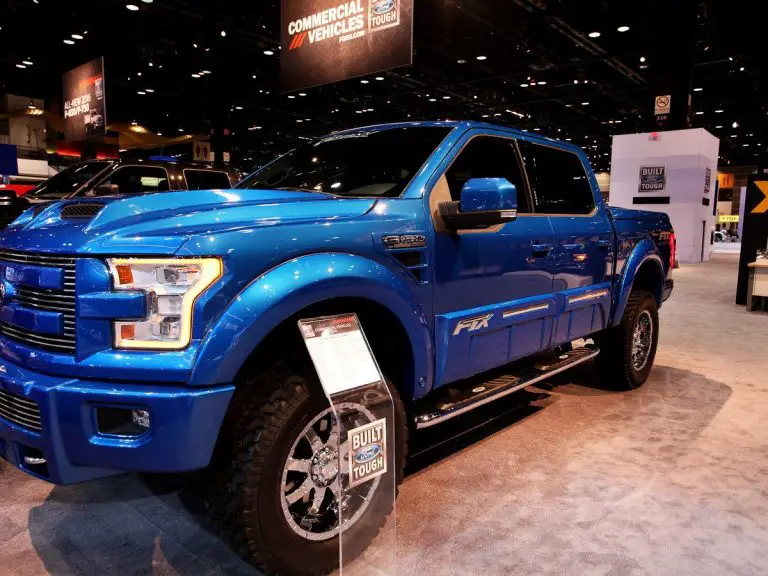
| EcoBoost V6 | 3.5L (F-150, Explorer, Flex) | Driver-side lower engine block, directly beneath the turbocharger assembly. | Access requires removal of the driver-side inner wheel well splash shield, localized heat shielding, and a rubber grommet. Secured by a 7mm bolt. | Moderate |
| EcoBoost V6 | 2.7L (F-150, Edge) | Front lower engine block, adjacent to the harmonic balancer and crankshaft pulley. | Accessed from underneath the vehicle by removing the aerodynamic splash shield. Secured by an 8mm bolt. | Easy |
| Coyote V8 | 5.0L (Mustang, F-150) | Rear of the engine block, integrated into the crankshaft sensor ring area. | Highly invasive access. Requires complete removal of the transmission, clutch assembly, and flywheel to access the sensor and reluctor ring. | Very High |
| Triton V8 | 4.6L / 5.4L 3V (F-150, Expedition) | Lower passenger side of the engine block. | Accessed from beneath the vehicle, located adjacent to the A/C compressor and harmonic balancer. Requires an 8mm socket and swivel extension. | Easy to Moderate |
| PowerStroke | 6.0L / 6.4L V8 Diesel | Lower front passenger side of the engine block. | Tucked tightly behind the starter motor and harmonic balancer. Removal often necessitates a pry bar and long extensions for the 8mm retaining bolt. | Moderate |
| PowerStroke | 6.7L V8 Diesel | Passenger side, mounted on a specific bracket inside the transmission bell housing. | Extremely tight clearance. Bracket alignment is notoriously difficult and critical; misalignment routinely causes persistent P0016 codes. | High |
| PowerStroke | 7.3L V8 Diesel (Legacy) | Front of the engine block, roughly at the 11 o’clock position above the dampener. | Technically functions as a Camshaft Position Sensor (CPS) reading a 24-window cam wheel to establish both RPM and TDC. Secured by a 10mm bolt. | Easy |
| Godzilla V8 | 7.3L Gas (Super Duty) | Internal, located behind the front timing cover. | Lacks a dedicated lower CKP; the system relies entirely on a camshaft position sensor reading a squared-window timing wheel. Secured by a 10mm bolt. | Moderate |
| Duratec I4 | 2.0L (Focus, Escape) | Rear side of the engine block near the transmission bell housing. | Accessed from beneath the vehicle. Requires standard metric sockets (8mm/10mm) and removal of underbody shielding. | Moderate |
EcoBoost Platform Analysis (2.7L and 3.5L V6)
The location of the CKP differs significantly between the two primary EcoBoost architectures. On the 3.5L EcoBoost (found extensively in 2011-2021 F-150s, Explorers, and Ford Flex models), the sensor is heavily obscured by forced induction plumbing. It is tucked behind the driver-side wheel well. Access requires the technician to remove the inner fender splash shield and a localized heat shield. Behind these components, a distinct rubber grommet conceals the sensor body, which is secured to the block by a single 7mm bolt.
Conversely, the 2.7L EcoBoost features a much simpler mounting strategy, placing the sensor at the lower front of the engine block, directly adjacent to the harmonic balancer and crankshaft pulley. A critical point of confusion often arises at the parts counter regarding the 2.7L engine: mechanics frequently confuse the primary crankshaft position sensor with the crankcase pressure sensor. The crankcase pressure sensor is a non-serviceable unit integrated into an emissions hose assembly (e.g., Ford part number FL3Z-6758-D) and does not read rotational timing.
Coyote Platform Complexity (5.0L V8)
The 5.0L Coyote engine represents one of the most mechanically intensive CKP architectures in the modern automotive landscape. Unlike traditional engines that read off the front harmonic balancer, the Coyote’s sensor and its corresponding reluctor ring are located at the extreme rear of the engine block. Replacing the sensor ring itself requires complete, invasive removal of the transmission, clutch (or torque converter), and flywheel.
Due to the hyper-sensitivity of this sensor and its vulnerable location, any mechanical shock or minor displacement occurring during routine transmission or exhaust maintenance can corrupt the sensor’s air-gap reading. This necessitates a digital “Crank Relearn Procedure” to synchronize the PCM to the new physical tolerances and prevent catastrophic engine misfire damage.
The 7.3L Architectural Anomaly: PowerStroke Diesel vs. Godzilla Gas
A fascinating architectural and engineering overlap exists between the legacy 7.3L PowerStroke Diesel (1994–2003) and the modern 7.3L “Godzilla” Gas engine (2020–Present). Despite utilizing completely different combustion principles, neither engine possesses a dedicated “crankshaft” position sensor in the traditional lower-block sense.
In the legacy 7.3L PowerStroke Diesel, the PCM relies entirely on a Hall Effect Camshaft Position Sensor (CPS) located at the 11 o’clock position above the front dampener. The corresponding cam wheel features 24 precision-machined windows (with the windows for cylinders #1 and #4 having distinct, alternate widths) to allow the PCM to calculate both exact engine RPM and absolute piston position simultaneously.
Failure of this specific sensor was historically so prevalent—often leaving drivers stranded without warning—that it resulted in massive(https://static.nhtsa.gov/odi/tsbs/2021/MC-10205552-9999.pdf) and multiple hardware redesigns from the original black sensor body to a revised grey unit.
Similarly, the modern 7.3L Godzilla V8 (a pushrod gas engine architecture) utilizes a single, highly advanced camshaft position sensor located inside the front timing cover. This sensor reads a squared-window timing wheel to deduce crankshaft rotation and cylinder firing order without requiring a secondary lower-block sensor.
Diagnostic Trouble Codes (DTCs) and Failure Symptoms
When a CKP sensor begins to degrade, it rarely results in an immediate, binary operational state. Instead, heat saturation from the engine block and internal copper winding degradation cause intermittent electrical signal dropouts. The PCM requires a continuous, unbroken wave pattern to accurately calculate Top Dead Center (TDC); when this pattern breaks even for a fraction of a second, the engine will exhibit immediate, severe drivability issues.
| Symptom / DTC | Mechanical Origin and Implications |
| Crank, No-Start Condition | The starter motor engages the flywheel, but the PCM refuses to trigger the fuel injectors or spark plugs because it cannot determine the engine’s rotational position. |
| Intermittent Stalling at Operating Temp | Thermal expansion of the internal copper windings within an inductive sensor causes microscopic breaks in the circuit, severing the signal completely until the engine cools. |
| Erratic Tachometer Operation | During cranking or idling, the dashboard RPM needle may bounce erratically or sit dead at zero, directly reflecting the PCM’s loss of the sensor signal. |
| P0335: Circuit Malfunction | Indicates a total loss of the electrical signal from the CKP circuit to the PCM, often caused by a fully severed wire, dead sensor, or unplugged connector. |
| P0336: Range/Performance | Indicates the PCM is receiving a signal, but the timing of the pulses (the waveform key) is illogical. Highly common on the 6.7L PowerStroke due to bracket misalignment. |
| P0300 – P0308: Random Misfires | To protect the engine from unburned fuel washing the cylinders, the PCM may retard timing and cut power, leading to bucking and random cylinder misfire codes. |
Technical Testing Methodologies: Inductive vs. Hall Effect Sensors
Before condemning the sensor and undertaking a complex, labor-intensive replacement, stringent electrical testing is mandatory. The diagnostic methodology depends entirely on whether the specific Ford engine utilizes an Inductive (Analog/Passive) sensor or a Hall Effect (Digital/Active) sensor.
Testing an Inductive CKP Sensor (2-Wire Architecture)
Inductive sensors are passive devices that generate their own power. They utilize a permanent magnetic core wrapped in hundreds of turns of fine copper wire. As the steel teeth of the engine’s reluctor wheel pass closely by the magnet, the magnetic field is distorted, generating an Alternating Current (AC) voltage.
| Diagnostic Test | Procedure | Expected Result for a Healthy Sensor |
| Resistance (Ohms) Check | Disconnect the sensor connector. Set the digital multimeter to the Ohms (Ω) scale. Probe the two sensor terminals directly. | A healthy Motorcraft inductive sensor typically reads between 200 and 1,000 ohms. A reading of zero indicates an internal short; infinite resistance (OL) indicates a broken internal winding. |
| AC Voltage Output Test | Reconnect the sensor. Back-probe the signal wires, set the multimeter to AC Voltage, and crank the engine. | The sensor should generate a rapidly fluctuating signal between 0.5V and 1.5V AC during cranking. |
| Oscilloscope Verification | Connect oscilloscope probes to the signal and ground wires. Crank the engine. | The screen must display a smooth, continuous sine wave pattern. Any flattened peaks indicate a damaged reluctor wheel tooth. |
Testing a Hall Effect CKP Sensor (3-Wire Architecture)
Hall Effect sensors utilize advanced semiconductor materials and require an external power source to operate. Instead of a sine wave, they output a crisp, digital square wave that the PCM can read with much higher fidelity at low RPMs.
| Diagnostic Test | Procedure | Expected Result for a Healthy Sensor |
| Verify Reference Voltage (VREF) | Turn the ignition to “ON” (engine off). Set the multimeter to DC Voltage. Check the power supply wire at the harness connector. | The PCM must supply a steady, unfluctuating 5.0 Volts DC. |
| Verify Ground Integrity | Set the multimeter to Ohms. Probe the ground wire terminal against a clean chassis ground. | Must show absolute continuity (less than 0.5 ohms of resistance). |
| Digital Signal Output Test | Back-probe the signal wire with the sensor connected. Crank the engine and observe the DC voltage. | The multimeter should show a rapidly pulsing DC voltage toggling between 0V and the 5V reference. |
According to experts at(https://www.delphiautoparts.com/en-gb/mom/how-to/article/how-to-test-your-crank-shaft-position-sensor), while a multimeter can verify basic voltage presence, an oscilloscope is highly recommended for Hall Effect testing. The oscilloscope must display a perfectly uniform, sharp square wave. Rounded edges, erratic spacing, or dropped pulses definitively indicate a failing internal semiconductor.
Second-Order Diagnostics: Wiring Harness Failures and Chafing
A critical second-order insight derived from high-level Ford diagnostics is that the presence of a P0335 or P0336 code does not guarantee a failed sensor. Extreme under-hood heat and continuous engine vibration are the primary enemies of the delicate CKP wiring harness.
In modern, tightly packaged engine bays, the wiring harness routing often forces the loom to cross over high-heat areas. As detailed in TSBs addressing harness contact (such as the conditions outlined in TSB 21-NA-149 for cross-platform diagnostics), normal engine torque causes the block to rock on its mounts. This repetitive motion causes the wiring harness to chafe heavily against the Camshaft Carrier Cover, the lower air cleaner housing, or the generator bracket.
Once the protective wire insulation degrades, the 5V reference wire shorts directly to the engine block ground. This short pulls the circuit voltage down from 5V to 0V (or creates a parasitic draw pulling it to a messy 8V on shared circuits), instantly killing the CKP signal and forcing the engine to stall.
Furthermore, if a technician discovers a broken CKP wire, soldering the connection is heavily discouraged by automotive electrical engineers. Solder creates a rigid, inflexible joint within the wire that is highly susceptible to cracking under continuous engine vibration, and it can introduce unwanted electrical resistance. Damaged CKP wires must always be repaired using high-quality, heat-shrink crimped terminals to maintain the precise micro-voltage integrity required by the PCM.
The Ford Crankshaft Position Sensor Relearn Procedure
Physical replacement of the sensor represents only half of the repair matrix. On modern Ford architectures—most notably the 5.0L Coyote and the 3.5L EcoBoost—the PCM must digitally “relearn” the exact microscopic variations in the distance between the new sensor’s magnetic tip and the reluctor wheel. Without this critical software recalibration, the PCM cannot accurately calculate rotational timing, which neutralizes the misfire monitor and can lead to severe catalytic converter damage.
| Relearn Methodology | Execution Procedure | Effectiveness |
| Battery Discharge Reset | Disconnect the negative battery cable for a minimum of 15 minutes. Depress and hold the brake pedal for 30 seconds to drain all residual capacitive charge from the PCM. Reconnect the battery and allow the vehicle to idle untouched for 10 minutes. | Passive; works on older generation ECMs, but often insufficient for modern EcoBoosts. |
| Automatic Idle Relearn | Install the new sensor, start the engine, and allow it to idle continuously for 10 to 15 minutes without applying any throttle input. The engine may run noticeably rough as the system auto-calibrates the fuel trims and timing parameters. | Low to Moderate success rate depending on the PCM generation. |
| Manual Drive Cycle | Warm the engine to full operating temperature. Drive the vehicle at a steady speed between 35 and 45 MPH for exactly 10 minutes. Immediately follow this with 10 minutes of heavy stop-and-go driving to expose the PCM to varied RPM and load ranges. | Moderate success rate; requires safe road conditions to execute properly. |
| Diagnostic Scan Tool (Forced Relearn) | Connect an advanced, bidirectional OBD-II scan tool. Navigate to the PCM “Special Functions” menu and select “Crank Relearn.” The software will prompt the user to bring the engine to operating temperature and momentarily floor the accelerator, revving the engine past 4,500 RPM until the PCM automatically cuts the fuel. The scanner will then report a “Calibration Successful” message. | Mandatory and Highly Effective. This is the only acceptable method for 5.0L Coyote engines to ensure transmission and exhaust maintenance does not destroy the engine. |
Replacement Economics: Labor Times and Part Costs
The financial economics of replacing a Ford crankshaft position sensor vary wildly based on the specific engine architecture and the location of the sensor. While the physical part is relatively inexpensive—a genuine Motorcraft replacement sensor generally costs between $30 and $60 depending on the application—the flat-rate labor times dictate the final repair bill.
For easily accessible engines like the 4.6L Triton, 5.4L Triton, and the 2.7L EcoBoost, standard labor times range from 0.5 to 1.5 hours. A typical repair facility will charge between $170 and $280 for the complete job.
Conversely, engines with extreme sensor placements demand premium labor rates. The 6.7L PowerStroke Diesel, requiring intricate access through the bell housing and meticulous bracket alignment, frequently bills out at 2.0 to 3.5 hours of labor. The 5.0L Coyote, requiring transmission removal to access the reluctor ring, can exceed 6.0 hours of labor. For these highly complex architectures, total replacement costs routinely range between $250 and $400+ at independent shops, and significantly higher at dealership service centers.
Questions (People Also Ask)
Can a bad crankshaft position sensor stop an engine from starting?
Absolutely. The CKP sensor acts as the primary “eyes” for the powertrain computer. If the PCM does not receive a valid, unbroken signal from the CKP, it cannot mathematically determine the position of piston #1. As an inherent safety fail-safe to prevent engine damage, the computer will actively cut power to the fuel injectors and ignition coils (or just the high-pressure injectors on a diesel platform), resulting in a continuous “crank, no-start” condition where the starter motor spins endlessly but the engine refuses to fire.
What is the difference between a camshaft and crankshaft position sensor on a Ford?
In traditional architectures, the crankshaft sensor monitors the rotational speed of the heavy lower engine block (the pistons and the crank), which primarily dictates base ignition timing and misfire detection. The camshaft sensor monitors the lighter upper valvetrain, dictating variable valve timing (VVT) parameters and sequential fuel injector synchronization. However, in highly specific Ford architectures—most notably the legacy 7.3L PowerStroke Diesel and the modern 7.3L Godzilla gas engine—the system relies on a single, highly complex camshaft sensor reading a specialized multi-window timing gear to deduce both upper and lower engine position simultaneously, rendering a lower crankshaft sensor obsolete.
Why do I still have a P0336 code after replacing the sensor on my 6.7L PowerStroke?
The P0336 code is specifically designated as a “Range/Performance” error. On the 6.7L PowerStroke diesel, the sensor bracket mounts deep inside the transmission bell housing. This bracket is an infamous engineering failure point. If the bracket is slightly bent during installation, has debris behind it, or is installed even slightly off-center, the microscopic “air gap” between the sensor’s magnetic tip and the reluctor wheel teeth will fall out of the required mathematical tolerance. The PCM will successfully read the voltage output, but it will immediately recognize that the physical waveform is malformed or delayed, and it will trigger the P0336 code despite the presence of a brand-new sensor. Utilizing an oscilloscope to verify the symmetry of the waveform is the only way to definitively prove the bracket is perfectly aligned.