Vacuum Line Routing Ford 460 Vacuum Diagram: Easy Guide
The vacuum line routing ford 460 vacuum diagram illustrates the connections between the engine intake manifold and the HVAC controls. It maps the path from the vacuum reservoir to the vacuum motors behind the dashboard, ensuring proper airflow direction and gate operation for the heating, ventilation, and air conditioning systems.
📌 Key Takeaways
- Vacuum lines are the primary method for directing airflow in older Ford HVAC systems.
- The vacuum reservoir tank is the most important component for consistent operation.
- Always relieve system pressure and label hoses before disconnecting during repairs.
- Replace brittle plastic lines with rubber vacuum hoses to prevent future leaks.
- Use this diagram when vents are stuck in defrost or airflow is weak.
Finding a reliable vacuum line routing ford 460 vacuum diagram is a critical step for any owner dealing with climate control failures or erratic engine performance. The Ford 7.5L 460 V8 engine relies heavily on vacuum pressure to operate both emissions equipment and the internal HVAC doors that direct airflow. When these lines fail, your air conditioning might default to the defrost vents, or your heater may refuse to engage. This article provides a comprehensive look at the routing path, identifying how vacuum pressure moves from the intake manifold to the internal air handler, ensuring your cabin stays comfortable regardless of the weather.
On the Ford 460 engine, vacuum is the “energy” used to toggle between the evaporator for cooling and the heat exchanger for warming. Without a consistent vacuum signal, the system defaults to a “fail-safe” mode, which usually directs all air to the windshield for safety.
Understanding the Ford 460 HVAC Vacuum Architecture
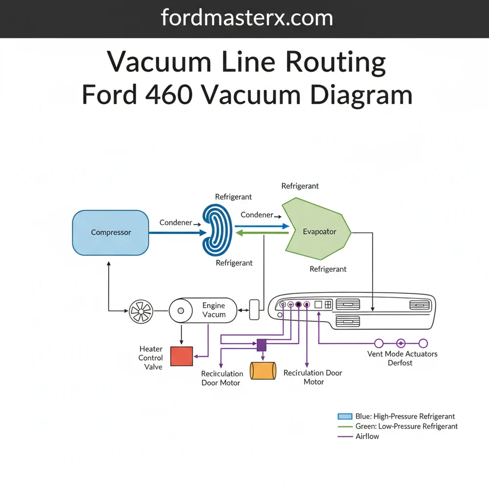
The vacuum system for the Ford 460 is divided into two primary circuits: the engine management circuit and the climate control circuit. For the purposes of HVAC restoration, we focus on the line that exits the intake manifold vacuum tree. This source line supplies the constant negative pressure needed to actuate the doors inside the air handler. The diagram below illustrates the flow of air and vacuum from the engine bay into the passenger compartment.
At the heart of the system is the vacuum reservoir, often referred to as the “coffee can” in older Ford models. This component acts as a storage tank for vacuum pressure, ensuring that when you accelerate and engine vacuum drops, there is still enough stored pressure to keep the AC compressor engaged and the vents in their correct position. From the reservoir, a primary vacuum line passes through the firewall via a multi-port rubber grommet. Once inside, it connects to the function selector switch on the dashboard. This switch acts as a traffic controller, redirecting vacuum to various actuators: the defrost door, the floor door, and the recirculating air door.
Visually, the diagram is color-coded to help you distinguish between different functions. In a standard Ford 460 setup, the black line is typically the source vacuum from the engine. The white line often controls the outside air/recirculate door located near the blower motor and evaporator core. Blue and yellow lines are generally assigned to the mix doors that determine if air passes through the heat exchanger or bypasses it for maximum cooling. Understanding these color codes is the first step in diagnosing why your refrigerant isn’t providing the cabin cooling you expect.
[DIAGRAM_PLACEHOLDER: A technical schematic showing a Ford 460 intake manifold connected to a vacuum reservoir. Lines lead from the reservoir through a firewall to a dash-mounted control head. From the control head, multiple colored lines branch out to vacuum actuators mounted on an HVAC air handler containing an evaporator, heat exchanger, and blower motor.]
Step-by-Step Guide to Interpreting and Routing Vacuum Lines
Correctly routing the vacuum lines on a Ford 460 requires a systematic approach. If you are replacing brittle plastic lines or reconnecting a disconnected system, follow these steps to ensure the HVAC system functions as designed.
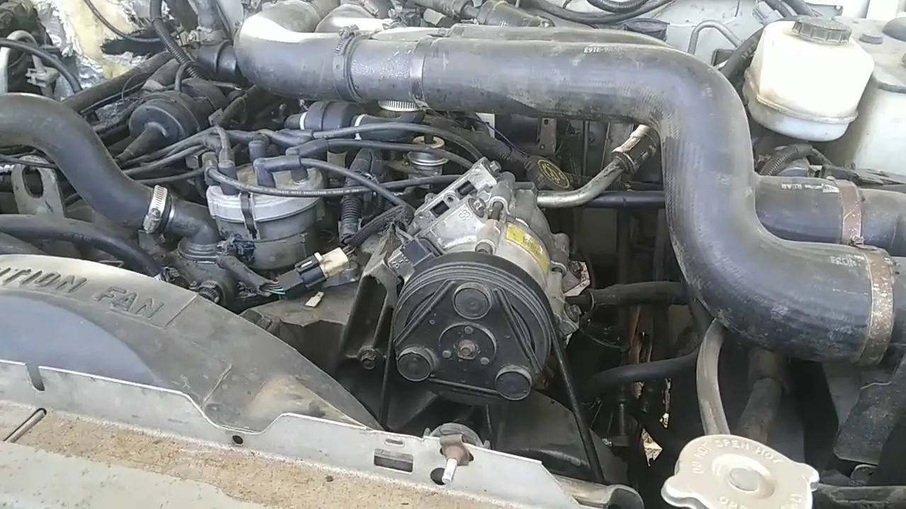
- ✓ Identify the Primary Vacuum Source: Locate the vacuum tree on the rear of the 460 intake manifold. Find the port designated for “HVAC” or “AC.” This is where the black supply line originates. Ensure the connection is tight and the rubber boot is not cracked.
- ✓ Inspect the Vacuum Reservoir: Follow the black line to the vacuum reservoir. This is usually mounted on the passenger side fender well. The reservoir must be airtight. Many enthusiasts replace the metal “can” with a modern plastic reservoir to prevent rust-related leaks.
- ✓ Trace Through the Firewall: From the reservoir, the vacuum line will head toward the firewall. There is often a check valve located here. This valve allows vacuum into the cabin but prevents it from escaping back toward the engine. Verify that the valve only flows in one direction.
- ✓ Access the Function Selector Switch: Behind the dashboard, the main supply line plugs into the back of the climate control head. This switch distributes vacuum to the different actuators. If you hear a “hissing” sound when moving the slider, the internal seals of the switch may be failing.
- ✓ Map the Actuator Lines: Each port on the selector switch corresponds to a specific actuator. The blue line typically goes to the floor/defrost door, while the red or yellow line goes to the heat/cool blend door. Ensure these lines are not pinched by dashboard supports.
- ✓ Verify the Recirculate Door: The white vacuum line usually runs back toward the passenger side kick panel. It controls the “Max AC” door. When vacuum is applied, it closes the return duct to the outside air and pulls air from inside the cabin, passing it over the evaporator for maximum cooling.
Never use generic rubber fuel hose for vacuum lines. Fuel hose is designed for internal pressure, while vacuum lines are designed to resist collapsing under external atmospheric pressure. Always use specific vacuum-rated tubing to prevent the lines from “pancaking” and cutting off the signal.
To perform this work, you will need a handheld vacuum pump, a set of small needle-nose pliers, and potentially a replacement vacuum harness if the original plastic lines have become too brittle. Safety is paramount; ensure the engine is off and the cooling system has depressurized before working near the heat exchanger or condenser areas in the engine bay.
Common Issues and Troubleshooting
The most frequent issue with the vacuum line routing ford 460 vacuum diagram is the “Defrost Only” failure. Because the system is designed to default to the windshield for safety, any loss of vacuum results in the doors snapping to the defrost position. If your blower motor is humming and you can hear the compressor clutch engaging, but air only comes out of the top of the dash, you have a vacuum leak.
Use the diagram to check the “coffee can” reservoir first. These are notorious for developing pinhole leaks due to corrosion. You can test this by applying 15 inches of vacuum with a handheld pump; if the needle drops, the reservoir is compromised. Another common failure point is the white line that runs to the recirculate door. Because it is exposed to the heat of the engine bay and the moisture of the evaporator housing, it often cracks right at the firewall entrance. If the refrigerant in your system is fully charged but the cabin isn’t getting cold, the recirculate door might be stuck open, forcing the system to constantly cool hot outside air instead of recycling the cooler air from the return duct.
If you are struggling to find a leak, use a small amount of unlit propane from a torch or a dedicated smoke machine. When the engine is idling, trace the lines. A change in RPM or visible smoke being sucked into a crack will reveal the exact location of the leak without guesswork.
Tips and Best Practices for Long-Term Maintenance
Maintaining the vacuum integrity of your Ford 460 is about more than just fixing leaks as they happen; it’s about preventing them through better materials and regular inspections. When replacing old lines, consider upgrading to silicone vacuum hoses. Silicone resists the high heat generated by the 460 V8 much better than the original nylon or rubber, and it remains flexible for decades without cracking.
- ✓ Secure with Zip Ties: Even though vacuum pulls the hose onto the fitting, engine vibrations can wiggle them loose. Use small zip ties at every junction, especially near the condenser and heat exchanger where thermal expansion is greatest.
- ✓ Clean the Check Valve: Every two years, remove the vacuum check valve and spray it with a bit of electronics cleaner. This ensures that oil vapors from the intake manifold don’t gum up the internal diaphragm, which could prevent the system from holding pressure.
- ✓ Protect Lines from Abrasion: Ensure that the vacuum harness is properly clipped away from the sharp edges of the air handler or the moving parts of the blower motor assembly.
Finally, always ensure your HVAC components are of high quality. If you find that an actuator is leaking internally (a common cause of partial vent movement), replace it with an OEM-spec unit. While it may be tempting to bypass the vacuum reservoir to save space, doing so will cause your vents to shift every time you go up a hill or accelerate to pass another vehicle. By following the vacuum line routing ford 460 vacuum diagram precisely and using quality components, you can ensure your classic Ford truck or motorhome remains a comfortable place to be for many miles to come.
Frequently Asked Questions
Where is the vacuum reservoir located?
The vacuum reservoir on most Ford 460 vehicles is typically located on the passenger side inner fender well or the firewall. It is often a black plastic canister or a metal tank designed to store vacuum pressure, ensuring that the HVAC doors function correctly even during low engine vacuum events.
What does the vacuum line routing ford 460 vacuum diagram show?
This vacuum line routing ford 460 vacuum diagram shows the network of hoses connecting the engine intake to the heater and air conditioning controls. It maps out how vacuum pressure is used to move the internal doors that direct air through the dash vents, floor, or defrost outlets.
How many vacuum lines connect to the HVAC controls?
The HVAC control head typically uses five to seven vacuum ports depending on the specific model. One port serves as the main vacuum supply from the engine, while the others lead to specific vacuum actuators for the floor, defrost, and dash vents to manage airflow distribution.
What are the symptoms of a bad vacuum actuator?
Common symptoms include air only blowing from the defrost vents regardless of the setting, a persistent hissing sound from the dashboard, or a blower motor that works well but cannot change the air direction. If the vacuum supply fails, the system defaults to defrost for safety reasons.
Can I replace Ford 460 vacuum lines myself?
Yes, replacing vacuum lines is a manageable DIY project with a clear routing diagram. You can replace brittle or cracked plastic lines with durable rubber tubing of the same inner diameter. It is a straightforward task that restores HVAC function and prevents vacuum-related engine idling issues.
What tools do I need for vacuum line routing?
You will need a handheld vacuum pump for testing, a set of pliers, and a sharp utility knife for cutting hoses. A vacuum gauge is also helpful for testing leaks at the reservoir, the compressor switches, or the vacuum connections leading into the cabin evaporator housing unit.


