Truck Tail Light Wiring Diagram: Easy Setup Guide
A truck tail light wiring diagram illustrates how electrical current flows from the battery to the rear lamps. It identifies the hot wire for power, the neutral wire or ground wire for circuit completion, and the common terminal for shared connections, ensuring turn signals, brake lights, and running lights function correctly.
📌 Key Takeaways
- The primary purpose is to map out the power and ground circuits for rear lighting
- The ground wire is the most critical connection for preventing flickering or dim lights
- Always disconnect the battery before working on electrical components to avoid shorts
- Use the diagram to distinguish between the traveler wire and fixed power leads
- This diagram is essential when installing a new flatbed or repairing trailer hitches
Understanding the intricacies of a truck tail light wiring diagram is the first step toward a successful DIY repair or custom installation. Whether you are replacing a damaged harness, upgrading to LED lighting, or troubleshooting a mysterious flicker, having a reliable map of your vehicle’s electrical system is essential for safety and functional integrity. Navigating through a sea of colored wires can be daunting, but a proper diagram simplifies the process by identifying pin connections and signal paths. In this guide, you will learn how to interpret standard color codes, identify specific terminal types, and execute a professional-grade wiring sequence that ensures your vehicle remains street-legal and visible in all conditions.
Most modern trucks follow a standardized color-coding system established by the SAE (Society of Automotive Engineers), but always verify with a multimeter before making permanent splices.
Decoding the Truck Tail Light Wiring Diagram
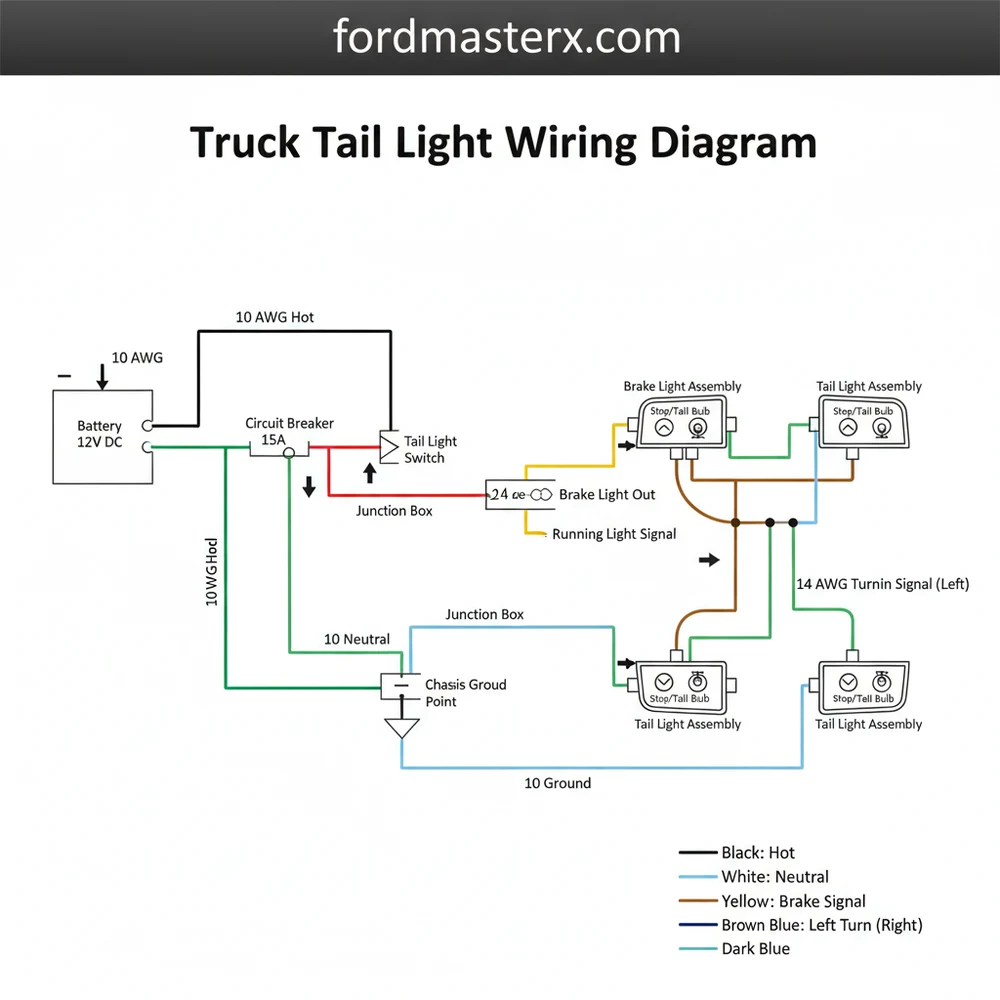
The primary purpose of a truck tail light wiring diagram is to illustrate how electrical current flows from the battery and light switch to the individual bulbs or diodes at the rear of the vehicle. These diagrams typically represent two main types of configurations: the 4-pin flat connector (common for light-duty towing and basic tail lights) and the 7-way round connector (standard for heavy-duty trucks with integrated brake controllers).
In a standard diagram, you will find several key elements. The hot wire is the conductor carrying current to the bulb, while the ground wire (usually white) completes the circuit back to the vehicle chassis. Unlike residential wiring which uses a neutral wire, automotive systems rely heavily on the chassis ground to manage the return path.
The visual breakdown of a 4-wire system usually includes:
- ✓ Green Wire: Right turn signal and brake light circuit.
- ✓ Yellow Wire: Left turn signal and brake light circuit.
- ✓ Brown Wire: Running lights or tail lights circuit.
- ✓ White Wire: The ground connection, which must be secured to a clean metal surface.
In more complex setups, such as those involving a 3-way switch or specialized lighting arrays, you might encounter a traveler wire. This wire allows for multiple switching points for auxiliary bed lighting or specialized strobe functions. Additionally, when looking at the back of a light housing, you may see a brass screw or terminal. This is often the common terminal where the power distribution happens within the light assembly itself.
graph LR
    A[Truck Battery] --> B[Light Switch]
    B --> C{Wiring Harness}
    C --> D[Brown: Tail Lights]
    C --> E[Yellow: Left Turn/Brake]
    C --> F[Green: Right Turn/Brake]
    C --> G[White: Ground Wire]
    D --> H[Common Terminal]
    E --> H
    F --> H
    G --> I[Chassis Ground]
Step-by-Step Installation and Wiring Guide
Following a truck tail light wiring diagram requires a methodical approach to ensure that connections are secure and weatherproof. Before you begin, gather the necessary tools, including a wire stripper, crimping tool, heat shrink tubing, and a digital multimeter to check voltage levels.
Always disconnect the negative battery terminal before working on the electrical system to prevent short circuits and blown fuses.
- Identify the Wire Gauge: Check the gauge of your existing harness. Using a wire that is too thin (high gauge number) for a long run can cause a voltage drop, resulting in dim lights. Most truck tail lights use 16 or 18-gauge wire.
- Locate the Common Terminal: Open the tail light housing and identify the common terminal. This is where the hot wire for the running lights usually connects. If your light uses a traditional bulb socket, this might be a brass screw or a specific metal tab.
- Prepare the Ground Wire: The white ground wire is the most critical connection. Strip about half an inch of insulation and crimp on a ring terminal. Secure it to a part of the truck frame that has been cleared of paint and rust to ensure a solid electrical path.
- Map the Turn Signals: Referencing your truck tail light wiring diagram, connect the yellow wire to the driver-side signal and the green wire to the passenger-side signal. In some systems, these also serve as the brake light wires (2-wire system), while others use a separate circuit.
- Handle the Traveler Wire (If Applicable): If you are installing custom auxiliary lighting that can be turned on from both the cab and the rear bed, you will need to route a traveler wire between the two switches. This acts as the bridge between the different switching positions.
- Secure Connections: Use marine-grade heat shrink butt connectors for all splices. This prevents moisture from entering the copper strands, which can lead to corrosion and high resistance over time.
- Test the Voltage: Reconnect the battery and use a multimeter. Set it to DC volts and touch the probes to the common terminal and the ground. You should see approximately 12.6V with the engine off and up to 14.4V with the engine running.
- Final Verification: Have an assistant stand behind the truck while you cycle through the running lights, left turn, right turn, and brake pedal to ensure the wiring sequence matches the expected output.
Common Issues & Troubleshooting

Even with a perfect truck tail light wiring diagram, problems can arise during the installation or over years of vehicle use. One of the most frequent issues is a “floating ground.” This occurs when the ground wire loses contact with the chassis, causing the lights to find a path through other bulbs. This often results in all lights dimming or flashing simultaneously when a single turn signal is activated.
Another common problem is voltage drop. If you notice that your tail lights are significantly dimmer than your headlights, use your multimeter to check the common terminal. If the reading is significantly lower than the battery voltage, your wire gauge may be too small for the length of the run, or there may be corrosion at a junction point.
If a specific light function isn’t working, check the hot wire for that circuit. Use the diagram to trace the wire back to the fuse box. In many trucks, the left and right sides are fused separately to ensure that a single failure doesn’t leave the vehicle completely dark at night.
If you are experiencing intermittent flickering, check the brass screw or spring tension inside the bulb socket. Vibrations from driving can loosen these physical contact points over time.
Tips & Best Practices for Wiring Longevity
To ensure your wiring job lasts the life of the truck, follow these professional recommendations:
1. Use Dielectric Grease: Apply a small amount of dielectric grease to every connection, including the bulb base and the brass screw terminals. This non-conductive grease seals out moisture and prevents the “green crust” of oxidation that plagues many older trucks.
2. Proper Wire Management: Never let your wiring harness hang loosely. Use UV-resistant zip ties to secure the wires along the inner frame rail, away from moving suspension parts and the heat of the exhaust system. This prevents the insulation from chafing and creating a short circuit.
3. Choose the Right Gauge: For standard tail lights, 16-gauge wire is usually sufficient. however, if you are adding high-powered work lights to the rear of the truck, consider stepping up to 12 or 14-gauge wire to handle the increased current draw and maintain stable voltage.
4. Quality Over Cost: When purchasing a new harness or connector, look for components with tinned copper wire. Tinned copper is much more resistant to corrosion than bare copper, which is especially important if you live in an area where road salt is used in the winter.
By strictly following the truck tail light wiring diagram and adhering to these best practices, you can create an electrical system that is both reliable and easy to maintain. Understanding the relationship between the hot wire, the common terminal, and the ground wire allows you to troubleshoot with confidence and ensures that your truck remains safe on the road. Whether you are dealing with a simple 4-pin setup or a complex multi-switch traveler wire configuration, the fundamentals of automotive electricity remain the same: clean connections, proper gauge selection, and a verified ground.
Frequently Asked Questions
Where is the tail light wiring harness located?
The harness is typically routed along the interior of the truck’s frame rail, leading from the engine bay or cabin to the rear bumper area. It terminates at the back of the tail light housing, where it plugs into the bulb sockets or a central junction block.
What does a truck tail light wiring diagram show?
The diagram displays the specific color-coded paths for the brake, turn signal, and reverse circuits. It highlights where the hot wire connects to each filament and how the neutral wire or ground path returns to the chassis, ensuring every light function receives the correct voltage for operation.
How many wires does a standard truck tail light have?
Most modern trucks use a four-wire system per side, including dedicated leads for the turn signal, brake light, and running lights, plus a shared ground wire. Some heavy-duty trucks may use additional wires for integrated backup sensors or specialized auxiliary lighting connected through a common terminal.
What are the symptoms of a bad tail light ground?
Common symptoms include dim bulbs, lights that turn off when you hit the brakes, or turn signals that flash rapidly. If the ground wire is loose, electricity may backfeed through other circuits, causing multiple lights to glow faintly when only one should be activated.
Can I replace the tail light wiring myself?
Yes, replacing or repairing the harness is a manageable DIY task using a truck tail light wiring diagram. By identifying the traveler wire and ensuring proper insulation at the common terminal, most owners can successfully restore lighting functionality with basic electrical tools and standard safety precautions.
What tools do I need for tail light wiring?
You will need a 12V test light or multimeter to identify the hot wire, wire strippers for prepping connections, and crimping tools for connectors. Electrical tape or heat shrink tubing is also necessary to protect the neutral wire and other connections from moisture and road debris.