Truck Front End Parts Diagram: Complete Component Guide
A truck front end parts diagram illustrates the complex assembly of steering, suspension, and body components. It maps out the layout of critical items like the bumper, grille, tie rods, and control arms. This visual guide allows you to understand the system configuration for efficient troubleshooting, maintenance, and replacement of parts.
📌 Key Takeaways
- Provides a visual map of the vehicle’s steering and suspension structure
- Critical to identify the steering rack and tie rod ends for alignment issues
- Always secure the vehicle on jack stands before inspecting front end components
- Use the diagram to verify the correct configuration before ordering replacement parts
- Refer to this guide when experiencing loose steering or uneven tire wear
Finding an accurate truck front end parts diagram is often the first step in successful vehicle maintenance, whether you are performing a routine inspection or tackling a complex repair. Understanding the intricate layout of your truck’s steering and suspension systems ensures that you order the correct replacement components and maintain the safety and handling characteristics of your vehicle. This comprehensive overview provides a detailed schematic of the typical front end configuration, helping you identify every critical part from tie rods to control arms. By mastering this blueprint, you will gain the confidence to diagnose issues early and execute repairs with professional precision.
Deciphering the Truck Front End Layout
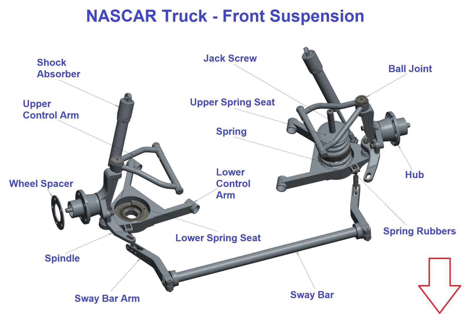
The front end of a modern truck is a sophisticated assembly of mechanical components designed to manage weight, absorb road impact, and provide precise directional control. When you look at a truck front end parts diagram, you are viewing a system configuration that typically falls into one of two categories: Independent Front Suspension (IFS) or a Solid Axle setup. Most light-duty and mid-size trucks utilize an IFS for better ride quality, while heavy-duty trucks often favor the robust nature of a solid front axle.
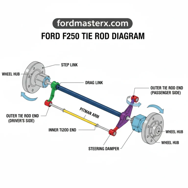
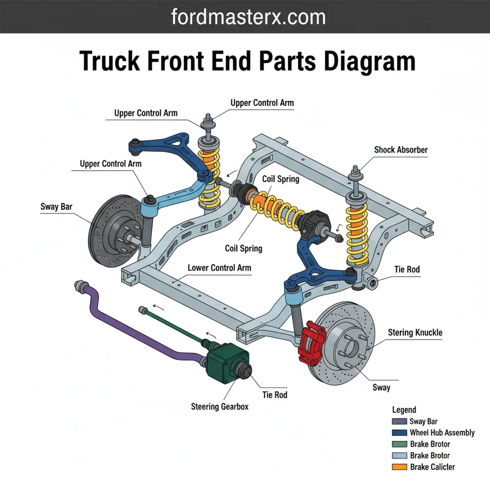
A standard diagram breakdown identifies the primary sub-systems: the steering linkage, the suspension geometry, and the braking assembly. In an IFS diagram, you will see upper and lower control arms, which act as the structural hinges for the wheel hubs. These are connected to the chassis via rubber or polyurethane bushings and to the steering knuckle via ball joints. The steering system, whether it uses a rack-and-pinion or a recirculating ball gearbox, is mapped out through inner and outer tie rods that connect the steering input to the wheels.
Visualizing these components in a schematic format often uses color-coding to differentiate between stationary chassis parts and moving suspension parts. For instance, the “sprung” weight components like the frame are often shown in a neutral grey, while “unsprung” components like the knuckles and rotors might be highlighted. Understanding this visual hierarchy is essential because it illustrates how force is transferred from the road through the tires and into the vehicle’s frame. Variations in these diagrams are common depending on whether your truck is two-wheel drive (RWD) or four-wheel drive (4WD), as the latter will include additional elements like CV axles, differential housings, and front drive shafts.
[DIAGRAM_PLACEHOLDER: A detailed 3D exploded view of a truck front end. Labels include: 1. Upper Control Arm, 2. Lower Control Arm, 3. Shock Absorber/Strut, 4. Steering Knuckle, 5. Outer Tie Rod End, 6. Sway Bar Link, 7. Wheel Hub Assembly, 8. Brake Rotor.]
While diagrams provide a general overview, always cross-reference your specific Vehicle Identification Number (VIN) when purchasing parts. Manufacturers often change component designs mid-year, and a VIN-specific search ensures the layout matches your exact build configuration.
How to Read and Apply the Front End Schematic
Interpreting a truck front end parts diagram requires a systematic approach. It is not just about identifying a single part; it is about understanding how that part interacts with the rest of the system. Follow these steps to effectively use a diagram for your next project.
- ✓ Step 1: Identify Your Steering Type – Determine if your truck uses a rack-and-pinion system or a steering box. This significantly changes the layout. A rack-and-pinion is more compact and common in half-ton trucks, whereas a steering box uses a pitman arm and idler arm common in three-quarter-ton or larger trucks.
- ✓ Step 2: Locate the Primary Pivot Points – Find the ball joints on your diagram. These are the critical junctions where the steering knuckle meets the control arms. If the diagram shows a “pressed-in” style, you will need a specialized press for replacement; if it shows a “bolt-on” style, the repair is much simpler for a DIYer.
- ✓ Step 3: Map the Load-Bearing Components – Identify the coil springs, leaf springs, or torsion bars. The diagram will show how these integrate with the shocks or struts. Understanding where the vehicle’s weight is supported is vital for safety when jacking up the truck.
- ✓ Step 4: Check for Sway Bar Integration – Look for the stabilizer bar (sway bar) and its end links. These often look like small “bones” on the diagram connecting the control arm to a long bar that spans the width of the truck. These are frequently the first parts to fail and cause rattling noises.
- ✓ Step 5: Verify Fastener and Torque Specifications – Most comprehensive blueprints include a table of torque specs for every bolt pictured. Never guess on these values; the front end is subject to extreme vibration and stress.
- ✓ Step 6: Use the Legend for Part Numbers – Match the numbered callouts on the diagram to the parts list. This is the most reliable way to find the exact “OEM” (Original Equipment Manufacturer) part number needed for a replacement.
When performing an installation based on the diagram, you will need a standard set of automotive tools, including a socket set, torque wrench, and potentially a “pickle fork” or ball joint separator. Always prioritize safety by using heavy-duty jack stands rated for your truck’s weight.
Never work under a truck supported only by a floor jack. Use jack stands placed on the frame rails as indicated by your vehicle’s shop manual to prevent catastrophic injury if the hydraulic system fails.
Common Issues and Troubleshooting

A truck front end parts diagram is your best friend when troubleshooting odd noises or handling behaviors. One of the most common issues is “death wobble” or significant vibration, which is often traced back to worn bushings or a failing steering damper in solid-axle trucks. By consulting the diagram, you can systematically check each connection point—starting with the track bar and moving to the tie rod ends—to find where the play exists.
If you notice uneven tire wear, such as “cupping” or “feathering,” the diagram helps you identify the components responsible for alignment. Cupping usually points toward worn shocks or struts that allow the tire to bounce, while feathering suggests an issue with “toe” settings, likely caused by worn tie rod ends. Look for leaking grease around the rubber boots of the ball joints or tie rods; the blueprint shows where these seals should be intact. If you see fluid leaking from a rack-and-pinion bellows, the diagram confirms that an internal seal has failed, likely necessitating a full rack replacement.
Pro Tips for Maintenance and Longevity
To get the most out of your truck’s front end, regular maintenance is mandatory. Many modern components are “sealed for life,” meaning they do not have grease fittings. However, if your truck features Zerk fittings on the ball joints or tie rods, you should grease them at every oil change. This flushes out contaminants and prevents metal-on-metal wear.
Whenever you replace a major front end component like a control arm or tie rod, you MUST get a professional alignment immediately. Even if the parts look identical, slight variations in manufacturing can ruin your tires in less than 500 miles if the alignment is off.
When selecting replacement parts, consider the “duty cycle” of your truck. If you frequently tow heavy loads or drive off-road, upgrading to “heavy-duty” or “greasable” aftermarket components can be more cost-effective in the long run than standard OEM replacements. These parts often feature thicker housings and better internal bearings designed to handle increased stress. Additionally, always replace components in pairs. If the left lower ball joint is worn out, the right one likely has the same amount of mileage and stress, and it will likely fail shortly after. Replacing them together saves you time and the cost of a second alignment.
By using a truck front end parts diagram as your primary reference, you move from guesswork to precision engineering. Understanding how each component contributes to the overall system allows you to maintain a vehicle that is safe, predictable, and durable. Whether you are a weekend warrior or a dedicated DIYer, the knowledge of your truck’s front end configuration is the key to a long-lasting and reliable ride.
Step-by-Step Guide to Understanding the Truck Front End Parts Diagram: Complete Component Guide
Identify – Start with identifying the specific section of the truck front end you are analyzing, such as the steering or suspension system.
Locate – Locate the main structural components, including the frame rails, control arms, and the steering gear box on the diagram.
Understand – Understand how the layout connects various parts, specifically how the tie rods link the steering rack to the wheel knuckles.
Apply – Apply the diagram configuration to your physical vehicle to match the visual representation with actual hardware for accurate diagnosis.
Verify – Verify that all fasteners, bushings, and joints shown in the diagram are present and in good condition on your truck.
Complete – Complete the inspection or repair by following the torque specifications associated with each component identified in the assembly guide.
Frequently Asked Questions
Where are the control arms located?
Control arms are situated between the vehicle’s chassis and the wheel hub assembly. In a standard truck configuration, you will find upper and lower control arms that allow the wheels to move vertically while maintaining proper alignment during steering and suspension travel.
What does a truck front end parts diagram show?
This diagram shows the complete layout of the steering, suspension, and cooling components located at the front of the vehicle. It provides a visual guide to the system structure, helping users identify parts like the radiator, stabilizer bar, and steering linkage for repair.
How many connections does the steering knuckle have?
A typical truck steering knuckle features several critical connection points. It connects to the upper and lower control arms via ball joints, the outer tie rod end for steering control, and the wheel hub assembly. This complex component is vital for both suspension and steering systems.
What are the symptoms of a bad front end component?
Common symptoms of a failing front end component include uneven tire wear, clunking noises when hitting bumps, and a steering wheel that vibrates or pulls to one side. A visual inspection using a diagram can help pinpoint if ball joints or bushings have failed.
Can I replace front end parts myself?
Many front end parts, like tie rods or sway bar links, can be replaced by experienced DIYers with the right tools. However, complex tasks involving the steering rack or pressed-in ball joints may require specialized equipment and a professional alignment immediately following the repair.
What tools do I need for front end repair?
You will typically need a heavy-duty jack, jack stands, a socket set, a torque wrench, and a tie rod separator or pickle fork. Specialized tools like a ball joint press may also be necessary depending on the specific component and the layout of your truck’s system.