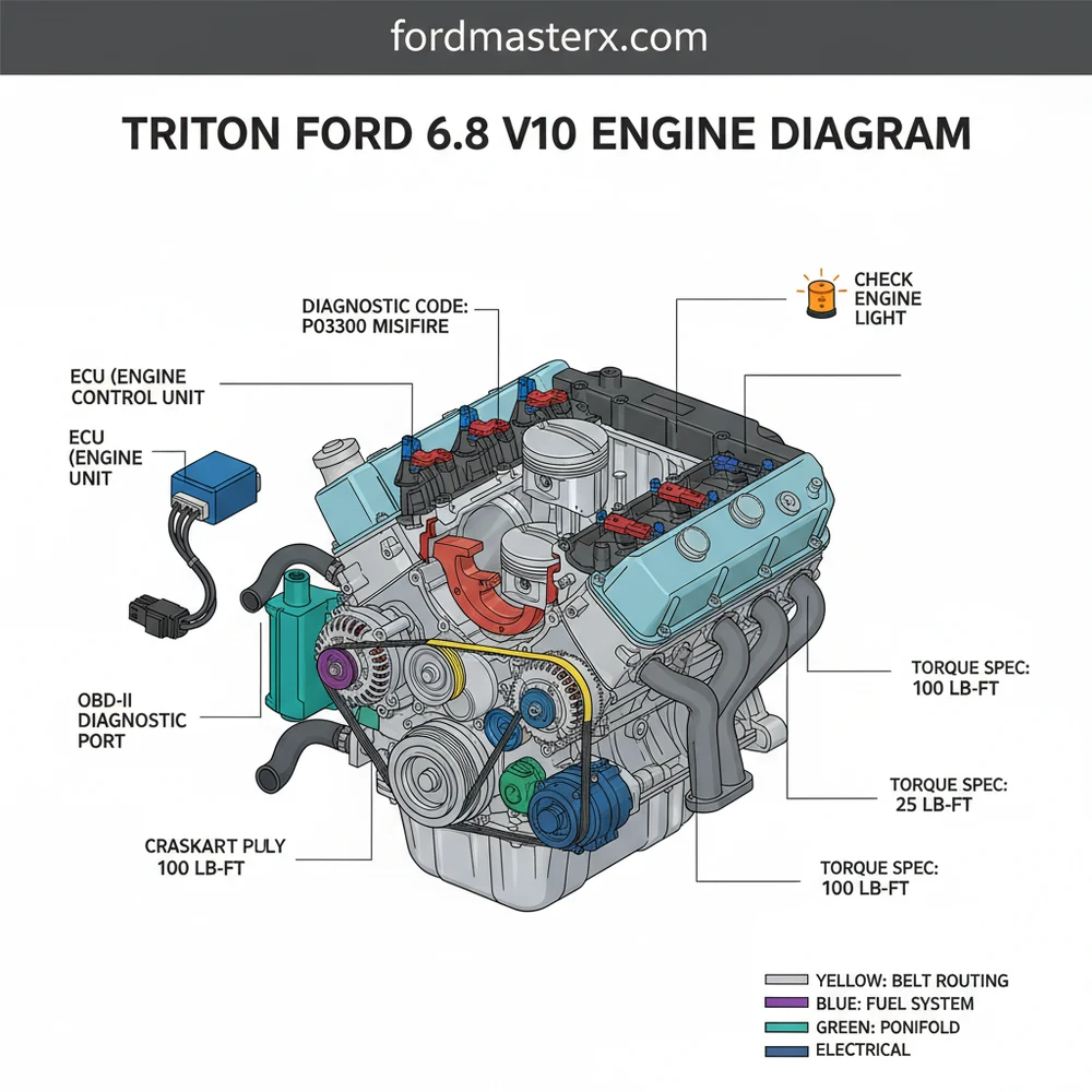
Triton Ford 6.8 V10 Engine Diagram: Complete Guide
The Triton Ford 6.8 V10 engine diagram illustrates the layout of the modular 3-valve or 2-valve overhead cam engine. It highlights the cylinder bank configuration, coil-on-plug ignition system, and the ECU connection points. This visual guide is essential for locating sensors and ensuring every torque spec is met during assembly.
📌 Key Takeaways
- Identifies the precise layout of the 10-cylinder modular engine architecture
- Helps locate the ECU and ignition coils for electrical troubleshooting
- Provides a reference for critical spark plug and manifold torque spec values
- Simplifies the process of reading a diagnostic code related to misfires
- Essential for owners of Ford Super Duty trucks and E-Series vans
The Ford 6.8-liter Triton V10 is a legend in the world of heavy-duty towing and commercial transport. Introduced in 1997 as part of Ford’s “Modular” engine family, it effectively bridged the gap between the smaller V8 engines and the massive diesel powerplants. For DIY enthusiasts, understanding the layout of this 10-cylinder beast is essential for maintenance, repair, and performance tuning. Whether you are working on an F-250 Super Duty, an E-Series van, or a massive Class A motorhome chassis, the V10 layout remains largely consistent. This guide provides a detailed breakdown of the engine’s architecture, wiring, and mechanical diagrams to help you navigate your way around the engine bay with confidence.
Main Components and Design Features
The 6.8L Triton V10 is essentially a 5.4L V8 with two additional cylinders. It features a cast-iron block and aluminum cylinder heads with a Single Overhead Cam (SOHC) design. Understanding the physical layout of these components is the first step in reading an engine diagram.
Cylinder Numbering and Firing Order
Unlike some engines where the numbering can be confusing, Ford follows a standard convention for the Modular family. When standing at the front of the vehicle looking at the engine:
- Passenger Side (Bank 1): Cylinders 1 through 5, with #1 being at the very front and #5 near the firewall.
- Driver Side (Bank 2): Cylinders 6 through 10, with #6 being at the very front and #10 near the firewall.
The firing order for the 6.8 V10 is 1-6-5-10-2-7-3-8-4-9. This specific sequence is designed to balance the inherent vibrations of a V10 engine, which utilizes a 72-degree firing interval made possible by a split-pin crankshaft.
The Ignition System (COP)
The Triton V10 uses a Coil-on-Plug (COP) ignition system. Instead of long spark plug wires running from a central distributor or pack, each cylinder has its own dedicated ignition coil sitting directly atop the spark plug.
- Wiring: Each COP connector has two wires. One is a common power wire (usually Red/Light Green on older models), and the other is a signal/ground trigger wire that goes back to the PCM (Powertrain Control Module).
- Primary Resistance: Generally measures between 0.55 and 0.60 ohms.
- Secondary Resistance: Generally measures between 5,500 and 6,000 ohms.
Intake and Vacuum System
The intake manifold on the V10 is a massive aluminum or composite structure. On the 2-valve models, you will find the IAC (Idle Air Control) valve located on the rear of the throttle body assembly. A common failure point in diagrams is the PCV (Positive Crankcase Ventilation) hose, which typically runs from the passenger side valve cover to the back of the intake plenum. Vacuum leaks here are notorious for causing “Lean” codes (P0171/P0174).
How to Use and Read a V10 Engine Diagram
Reading a Ford engine diagram requires an understanding of how Ford categorizes its systems. Most service manuals will separate diagrams into Mechanical, Electrical, and Vacuum/Emissions.
1. Identifying Wire Colors
In a wiring diagram for the V10, colors are abbreviated. For example, “LG/RD” means Light Green with a Red stripe. When troubleshooting a misfire, find the cylinder number on the diagram and trace the wire color back to the PCM. This helps you determine if a misfire is caused by a bad coil or a break in the harness.
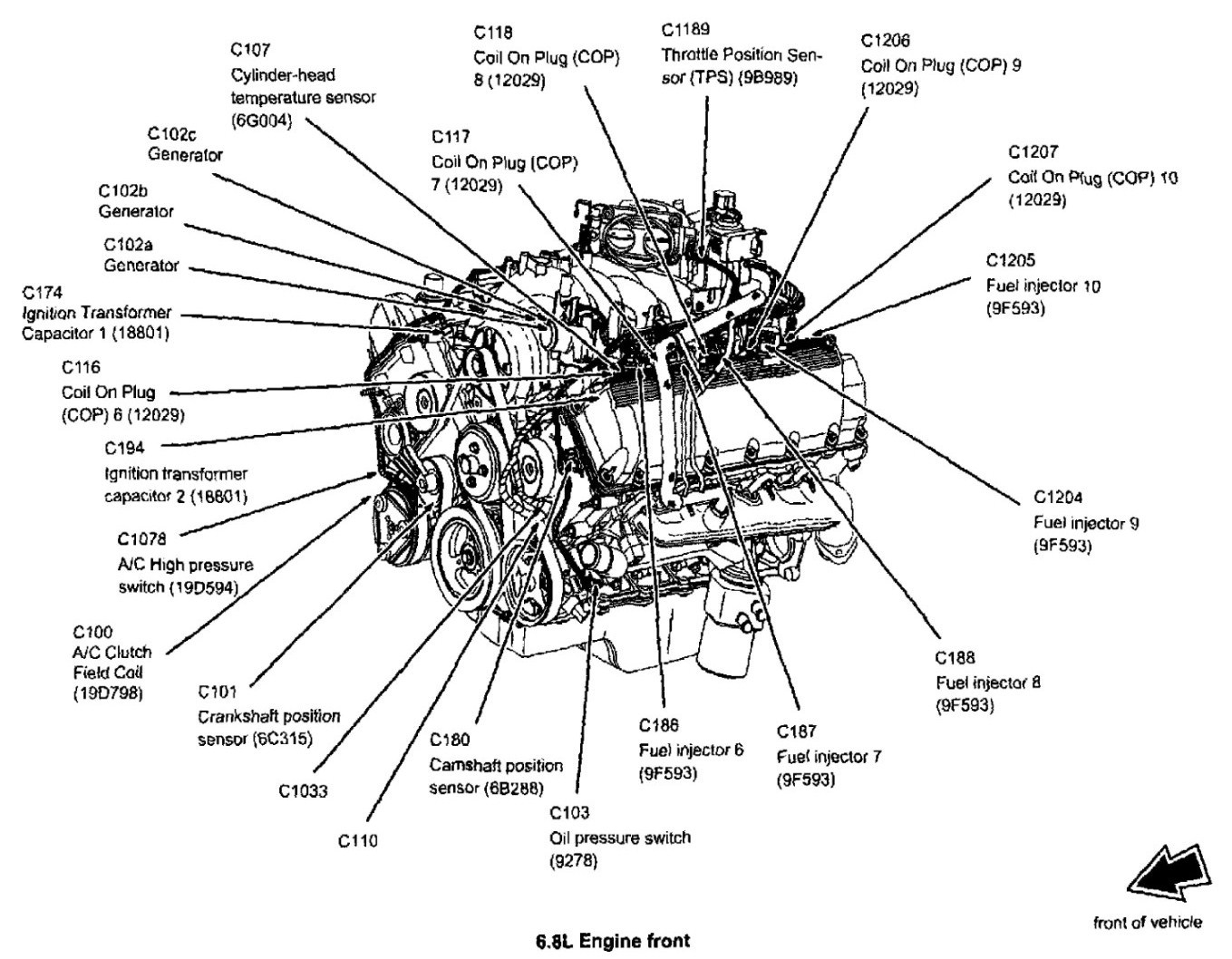
2. Locating Sensors
A typical V10 diagram will highlight several key sensors that DIYers need to know:
- MAF Sensor (Mass Air Flow): Located on the air intake tube between the air filter box and the throttle body.
- CKP Sensor (Crankshaft Position): Located on the front cover, near the AC compressor (bottom passenger side). This is vital for engine timing.
- CMP Sensor (Camshaft Position): Located on the front of the driver-side cylinder head (Bank 2).
- CHT Sensor (Cylinder Head Temperature): Located in the “valley” of the engine under the intake manifold. This sensor is unique because it doesn’t touch coolant; it measures the metal temperature directly.
3. Belt Routing Diagram
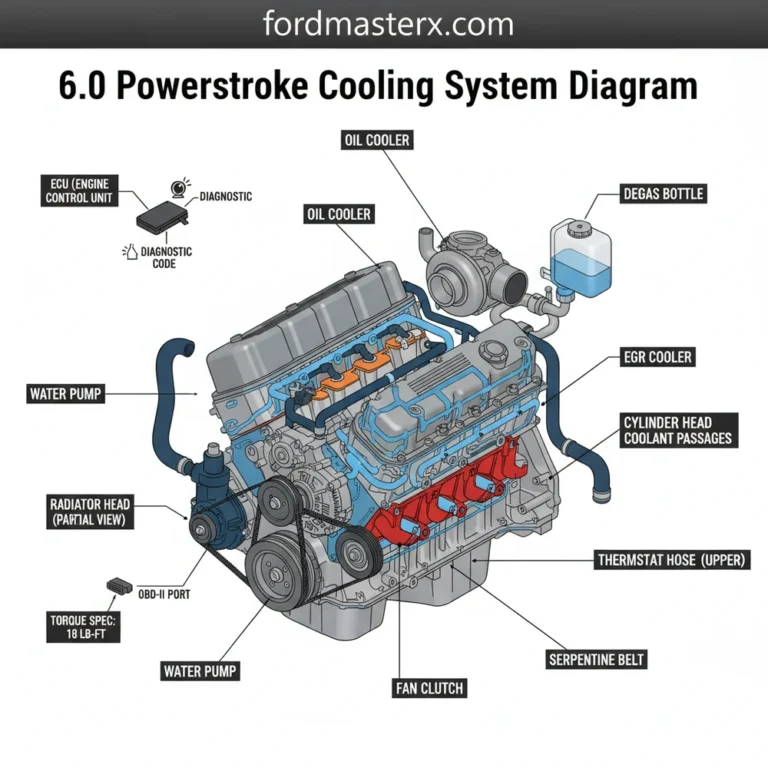
The serpentine belt on the V10 is exceptionally long. Most diagrams will show the belt wrapping around the alternator (top center), power steering pump (lower driver side), AC compressor (lower passenger side), and the water pump (center). Always check the diagram sticker on the radiator shroud before removing the belt, as the routing is not always intuitive.
Maintenance and DIY Tips

Working on a V10 requires some patience due to the engine’s length. The back cylinders (5 and 10) are tucked under the cowl, making access difficult.
- Oil Capacity: Most 6.8L V10s require 6 quarts of 5W-20 or 5W-30 motor oil (check your oil fill cap for the specific weight). Using a high-quality FL-820S Motorcraft filter is highly recommended to maintain oil pressure.
- Spark Plug Access: When changing plugs, blow out the “wells” with compressed air before removing the plug. Debris often falls into these deep holes and can drop into the combustion chamber.
- Coolant: The V10 holds a significant amount of coolant (approximately 27–30 quarts depending on the radiator size). Use the gold or orange Motorcraft coolant specified for your year to prevent internal corrosion of the aluminum heads.
Troubleshooting Common V10 Issues
Using your diagram and knowledge of the components, you can troubleshoot the most common “Triton” ailments.
The “Ticking” Sound
If you hear a persistent tick that sounds like a sewing machine, check your exhaust manifold studs. The V10 is famous for snapping the rear-most studs (usually on the passenger side). A diagram of the exhaust system will show 10 studs per side; if the head of one is missing, you have an exhaust leak. This can often be mistaken for an internal engine knock.
Misfire Under Load
If the engine stutters when going uphill but doesn’t throw a Check Engine Light (CEL), it is likely a “weak” COP. Use a scan tool to look at “Mode $06” data. This data shows misfire counts for each cylinder (1 through 10) even if the threshold to trigger a light hasn’t been reached yet. Match the cylinder number from your scan tool to your engine diagram to find the culprit.
Vacuum Leaks and Rough Idle
If the engine idles poorly but runs fine at speed, consult your vacuum routing diagram. Check the “elbow” at the back of the intake manifold. This rubber piece often rots out from the inside due to oil vapor. It is a $10 part that causes massive headaches but is easily identified if you know where the PCV line terminates on the diagram.
The “Death Wobble” of the Spark Plug
On 2005–2008 3-valve engines, the spark plugs were a two-piece design that frequently broke off in the head. If you are working on a 3V V10, always have a “Lisle Spark Plug Remover Tool” on hand before you start the job. Use the diagram to identify the plug locations and take your time, using a dedicated carb cleaner to soak the threads if they feel tight.
By understanding the layout, wiring, and component locations of the Triton 6.8L V10, you can keep this workhorse on the road for hundreds of thousands of miles. Whether you’re tracking down a ghostly electrical ground or simply performing a routine tune-up, the key is a methodical approach and a clear understanding of the V10’s unique architecture.
Step-by-Step Guide to Understanding the Triton Ford 6.8 V10 Engine Diagram: Complete Guide
Identify – Start with identifying the specific year and valve count (2V or 3V) of your 6.8 V10 engine.
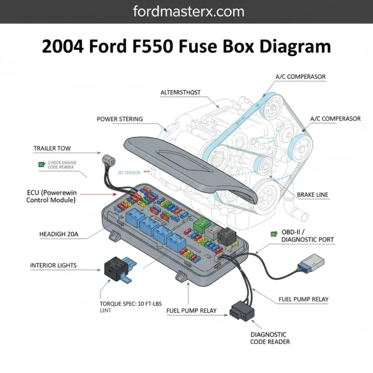
Locate – Locate the primary components such as the air intake, throttle body, and the ECU harness on the diagram.
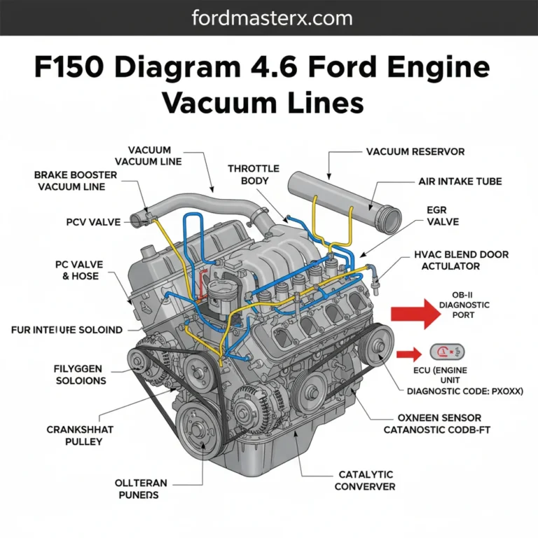
Understand – Understand how the vacuum lines and fuel rails are routed across the cylinder banks.
Apply – Apply the specific torque spec to each bolt when reinstalling components like the ignition coils or intake manifold.
Verify – Verify that all sensor connections are secure by matching the physical wires to the diagram’s color-coded paths.
Complete – Complete the process by using an OBD-II scanner to ensure no diagnostic code remains active before starting the engine.
Frequently Asked Questions
Where is the ECU located?
On most Ford vehicles equipped with the 6.8 V10, the ECU (Engine Control Unit) is located behind the dashboard on the passenger side or mounted on the firewall inside the engine bay. The diagram shows the wiring harness leading directly from the main sensors to this central module.
What does the Triton Ford 6.8 V10 engine diagram show?
This diagram displays the physical arrangement of the cylinders, the serpentine belt routing, and the placement of sensors like the MAF and O2 sensors. It also illustrates the vacuum line routing and the connection points for the fuel injectors and coil-on-plug ignition systems.
How many spark plug connections does this V10 have?
The 6.8 V10 engine features ten individual spark plug connections, each utilizing a dedicated coil-on-plug (COP) unit. The diagram highlights the firing order and the specific wiring paths for each coil to ensure the ignition system is correctly synchronized with the engine’s timing.
What are the symptoms of a bad ignition coil?
Common symptoms include a rough idle, reduced power, and a flashing check engine light. Using an OBD-II scanner will often reveal a specific diagnostic code, such as P0301 through P0310, which identifies exactly which cylinder is misfiring based on the engine diagram layout.
Can I replace the intake manifold myself?
Replacing the intake manifold is a moderately difficult DIY task that requires removing the fuel rails and several electrical connectors. By following the engine diagram and ensuring you use the correct torque spec for the mounting bolts, a determined hobbyist can successfully complete this repair in a day.
What tools do I need for V10 spark plug service?
You will need a 5/8-inch spark plug socket, a variety of socket extensions, and a calibrated torque wrench. An OBD-II reader is also recommended to clear any stored codes and verify that the check engine light remains off after the installation is finished.