Super Duty Ford F250 Brake Line Diagram: Complete Guide
The super duty ford f250 brake line diagram maps the hydraulic path from the master cylinder through the ABS module to each caliper. It details the hard lines and flexible hoses used to transfer pressure. This visual guide is essential for identifying leak points or replacing corroded lines to maintain vehicle safety.
📌 Key Takeaways
- Visualizes the complete hydraulic circuit from master cylinder to wheels
- Identifies the ABS control module as the central distribution point
- Crucial for safety to ensure no air or leaks exist in the lines
- Helps determine exact line lengths and fitting types for replacements
- Essential during brake bleeding or when addressing a soft brake pedal
When you are dealing with a heavy-duty pickup designed for towing and hauling, the integrity of the hydraulic system is not just a matter of performance—it is a critical safety requirement. Understanding a super duty ford f250 brake line diagram is the first step for any owner or technician looking to diagnose a soft pedal, replace corroded lines, or upgrade to stainless steel components. This comprehensive guide provides a detailed visual and technical breakdown of how fluid travels from the master cylinder to each wheel, ensuring you have the knowledge to maintain your truck’s stopping power effectively. By the end of this article, you will understand line routing, component identification, and the necessary procedures for a successful repair.
Understanding the Anatomy of the Super Duty Brake System
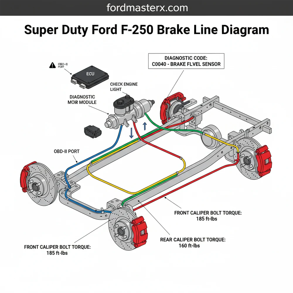
The brake line architecture of a Super Duty truck is significantly more robust than that of a standard passenger vehicle. The system begins at the master cylinder, typically mounted to a vacuum booster or a Hydroboost unit in diesel models. A comprehensive super duty ford f250 brake line diagram illustrates a split-circuit system, usually divided into front and rear channels. This ensures that if a leak occurs in one section, the vehicle retains partial braking ability.
The primary lines run from the master cylinder into the ABS (Anti-lock Braking System) hydraulic control unit. This unit acts as the “brain” of the hydraulic distribution, receiving signals from the vehicle’s ECU to modulate pressure during a skid. From the ABS module, the lines are routed along the driver-side frame rail. The front lines are relatively short, branching off to the left and right front wheels via flexible rubber or braided steel hoses. The rear line is a single long run that travels back to a junction block mounted on the rear axle housing, where it splits to serve the two rear calipers.
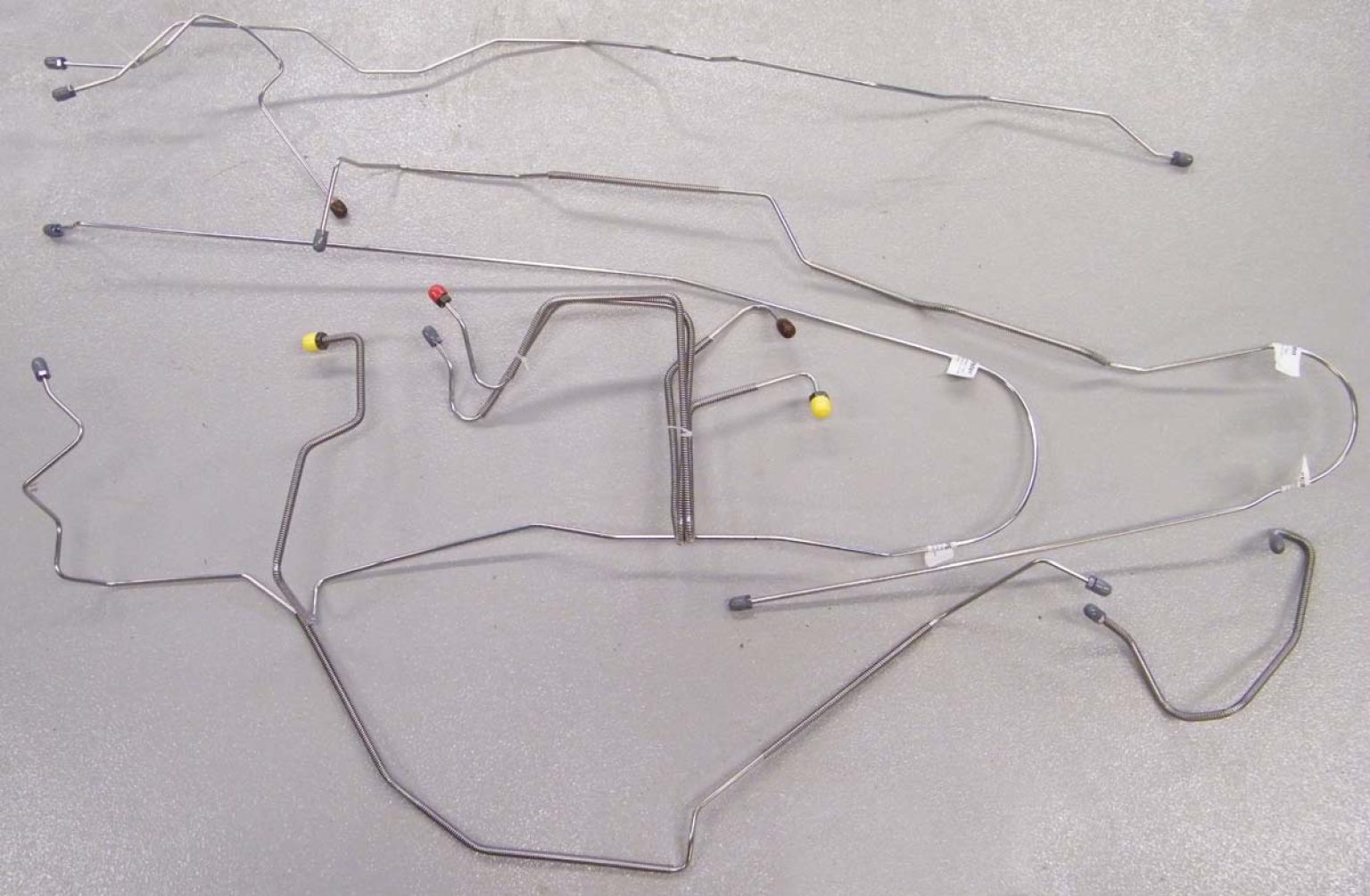
Visualizing these components is easier when you categorize them by their material and function. Hard lines are made of coated steel or nickel-copper and are designed to handle high pressures without expanding. In contrast, flexible hoses at the wheels allow for suspension travel and steering movement. On a Super Duty, these lines are often protected by plastic clips or metal shields to prevent abrasion during off-road use or heavy articulation.
Diagram shows: Master Cylinder, ABS Module, Frame Rail Routing, Rear Axle Junction, and Caliper Feed Lines.
Step-by-Step Guide to Reading and Implementing the Diagram

Interpreting a super duty ford f250 brake line diagram requires a systematic approach. Whether you are replacing a single rusted section or the entire vehicle’s plumbing, follow these steps to ensure accuracy and safety.
- 1. Locate the Primary Feed: Start at the master cylinder. Identify the two main ports. The larger reservoir section usually feeds the front brakes, while the smaller section feeds the rear, though the ABS module manages the final distribution.
- 2. Trace the ABS Routing: Follow the lines from the master cylinder to the ABS hydraulic unit. In many F250 models, this unit is located under the battery tray or along the inner fender well. Ensure the lines enter the correct “In” ports and exit the “Out” ports as designated by the diagram.
- 3. Map the Frame Rail Path: The longest section of the brake system runs along the inside of the driver-side frame rail. When using a diagram, note the locations of the mounting brackets. These are crucial for preventing vibration-induced fatigue in the metal lines.
- 4. Identify Junction Points: Locate the “T-junctions.” For the rear brakes, the single line from the front enters a junction block on the axle. From here, two separate lines go to the left and right rear wheels.
- 5. Prepare Your Tools: You will need flare nut wrenches (10mm, 12mm, and 13mm are common), a high-quality double-flaring tool or ISO bubble flaring tool (depending on the year), and a tubing bender to match the contours shown in the diagram.
- 6. Installation and Bleeding: Once lines are bent and flared, install them into the fittings. Use a torque spec of approximately 10-15 lb-ft for flare nuts, though you should always check the service manual for your specific year. Finally, perform a full system bleed starting from the wheel furthest from the master cylinder.
Never use a standard “compression fitting” on a brake line. These are designed for low-pressure plumbing and can fail under the extreme hydraulic pressures generated during an emergency stop. Always use proper flared connections.
Common Issues and Troubleshooting
F250 owners often face specific challenges due to the environment in which these trucks operate. The most common issue is external corrosion. Because the brake lines run along the frame, they are constantly bombarded by road salt and moisture. If you notice a “spongy” brake pedal or a drop in fluid levels, use your diagram to inspect the common failure points: the bends near the fuel tank and the junction block on the rear axle.
Another frequent problem involves the ABS system. If your check engine light or ABS light illuminates, you should connect a scanner to the OBD-II port. This can reveal a diagnostic code related to a wheel speed sensor or an internal failure in the ABS module’s ECU. If the code suggests a hydraulic fault, the diagram helps you identify which specific line or valve within the unit might be blocked or leaking.
On many Super Duty trucks, the brake system is integrated with the Hydroboost system, which uses power steering fluid to assist braking. If you see a leak near the master cylinder, determine if the fluid is clear/amber (brake fluid) or red/brown (power steering fluid) before beginning repairs.
Tips and Best Practices for Brake Maintenance
When replacing lines on your F250, consider upgrading to nickel-copper (NiCopp) or stainless steel lines. These materials are significantly more resistant to corrosion than the factory-style coated steel. This is especially important for vehicles that spend time at boat ramps or in snowy climates.
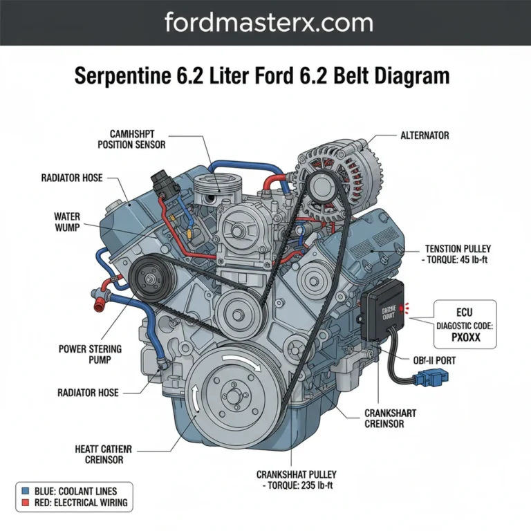
Whenever you have the truck on stands to work on the brake lines, take five minutes to perform a “surrounding system inspection.” Check the condition of your accessory belt and look for any signs of restricted coolant flow or leaks near the water pump. It is much easier to address these issues while the vehicle is already prepped for service.
Maintenance doesn’t stop at the lines. For a heavy truck, brake fluid should be flushed every two to three years. Brake fluid is hygroscopic, meaning it absorbs water over time, which can lead to internal corrosion of the lines and the ABS module. Using the super duty ford f250 brake line diagram as a guide, you can identify every bleeder screw location to ensure a complete flush of the old, contaminated fluid.
While the brake system is independent of the engine’s internal components like the timing chain, the overall health of your vehicle depends on synchronized maintenance. Keeping your hydraulic lines in peak condition ensures that your truck remains a reliable tool for work or play. Always double-check your connections and test your brakes in a safe, low-speed area after any repair. If you are ever unsure about the integrity of a flare or a fitting, consulting a professional technician is the safest course of action. Following these guidelines and using a high-quality super duty ford f250 brake line diagram will keep your truck stopping safely for miles to come.
Frequently Asked Questions
Where are the brake lines located on an F250?
Brake lines run from the master cylinder under the hood, down the driver-side frame rail, and branch out to the front wheels and rear axle. The rear lines typically follow the interior of the frame before splitting at a junction block located on the rear axle housing for each wheel.
What does this brake line diagram show?
This diagram illustrates the hydraulic routing for the front and rear circuits, including the master cylinder, ABS module, and proportional valves. It helps you trace lines through the chassis, ensuring each connection is correctly placed to maintain the dual-circuit safety system required for heavy-duty towing and braking performance.
What are the brake line connection specifications?
F250 brake lines typically use 3/16-inch or 1/4-inch tubing with double flares or ISO bubble flares. When tightening fittings into the ABS module or calipers, always refer to the factory torque spec to prevent stripping threads or causing leaks. Proper sealing is vital for maintaining high-pressure hydraulic integrity.
What are the symptoms of a leaking brake line?
A soft or spongy brake pedal usually indicates air or a leak in the system. You might see a check engine light or brake warning light if fluid levels drop. Use an OBD-II scanner to check for a diagnostic code related to low pressure or ABS malfunctions managed by the ECU.
Can I replace F250 brake lines myself?
Yes, replacing brake lines is a manageable DIY task with the right tools. Ensure you have a flare nut wrench and a high-quality flaring kit. After installation, the entire system must be properly bled to remove air pockets, ensuring the master cylinder provides consistent pressure to all four wheels.
What tools do I need for brake line repair?
You will need flare nut wrenches, a tube cutter, a flaring tool, and jack stands. Additionally, an OBD-II scan tool is helpful for cycling the ABS pump during the bleeding process, especially if the ECU has logged a diagnostic code following a significant fluid loss or component replacement.