Output Shaft Speed Sensor Circuit: Technical Diagnostics And Repair Procedures
A vehicle’s transmission relies on precision timing, and the output shaft speed sensor circuit serves as the primary nervous system for this complex mechanical dance. When this circuit fails, drivers face erratic shifting, loss of speedometer accuracy, and the dreaded limp-home mode, often leaving them questioning the integrity of the entire transmission. This expert guide provides a comprehensive analysis of the OSS circuit, detailing how to diagnose fault codes, test electrical continuity, and perform professional-grade repairs to restore vehicle performance.
Understanding Output Shaft Speed Sensor Circuit Functionality
📤 Share Image
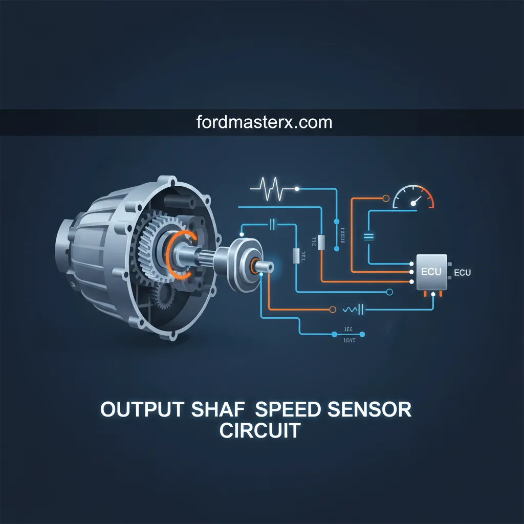
The Output Shaft Speed (OSS) sensor is a sophisticated transducer designed to monitor the rotational velocity of the transmission’s output shaft. Positioned at the rear of the transmission case, it tracks the movement of a reluctor wheel or a specialized gear. This data is transmitted to the Transmission Control Module (TCM) or Powertrain Control Module (PCM), where it serves as a primary input for shift scheduling and torque converter clutch (TCC) engagement.
While the Input Shaft Speed (ISS) sensor monitors engine load and turbine speed, the OSS circuit is focused on actual vehicle ground speed. A trusted signal from this circuit is non-negotiable for modern vehicles; it doesn’t just manage the transmission, it often feeds the speedometer and coordinates with the Anti-lock Braking System (ABS) to ensure stability control algorithms have accurate data.
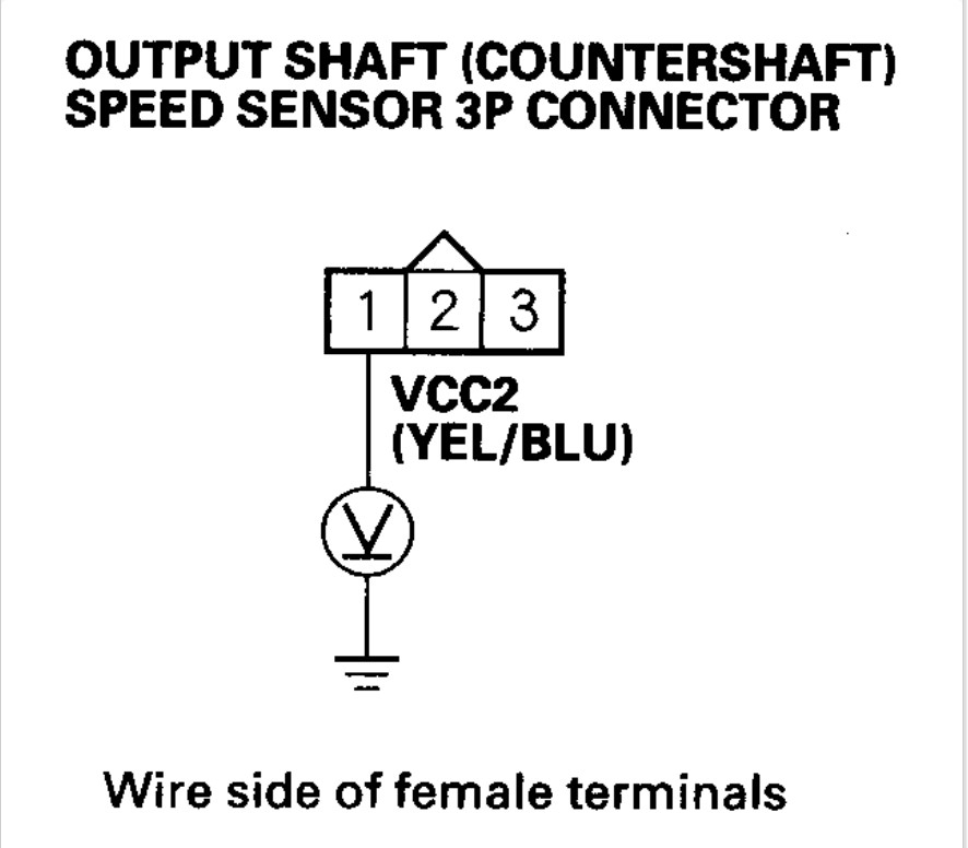
Sensor Architecture: VR vs. Hall Effect
Most modern automotive systems utilize a 5-volt reference signal to maintain a reliable digital communication path. This allows for pulse-width modulation (PWM) that is less susceptible to low-voltage dropouts. In contrast, older or heavy-duty industrial systems may still utilize a 12V reference for increased signal-to-noise ratios in electrically “noisy” environments.
Common Diagnostic Trouble Codes (DTCs)
When the PCM detects a deviation in the OSS circuit, it logs specific Diagnostic Trouble Codes (DTCs). Understanding these codes is the first step in expert-level troubleshooting.
P0720: Circuit Malfunction
A general electrical failure detected. This usually indicates an open or shorted circuit within the wiring or the internal sensor coil.
P0721: Range/Performance
Indicates an erratic signal. Typically triggered by electromagnetic interference (EMI) or a damaged reluctor wheel tooth.
Identifying intermittent signal issues with P0721 requires a high-quality scan tool capable of viewing freeze frame data. As an industry expert, I often look for the “snapshot” of the engine load, temperature, and speed at the moment the code was thrown. For example, if a P0720 is triggered only when the transmission reaches operating temperature, it suggests a thermal expansion issue causing an internal break in the sensor’s copper windings.
The PCM compares the OSS reading with the ISS and wheel speed sensors. A discrepancy of more than 5% between the calculated speed and the actual OSS reading typically triggers a P0721 code within two consecutive drive cycles.
Symptoms of a Failing Output Shaft Speed Sensor Circuit
The real-world performance issues resulting from a circuit failure range from minor annoyances to total vehicle immobilization. The most prominent symptom is the transmission “Limp Mode.” To protect the mechanical internals from incorrect shift timing, the TCM defaults to a single gear (usually 2nd or 3rd) and limits engine RPM to approximately 3,000.
Other symptoms include:
- Erratic Speedometer Behavior: The needle may “bounce” or drop to zero while driving if the continuity of the circuit is broken.
- Harsh Gear Engagement: Abrupt shifting, especially into 1st or Reverse, as the PCM lacks the data to modulate line pressure correctly.
- Loss of Cruise Control: Since cruise control relies on a stable OSS signal to maintain speed, the system will automatically disengage or refuse to set.
- Transmission “Hunting”: A common expert observation is a vehicle hunting between 3rd and 4th gear because the PCM cannot confirm the actual output shaft velocity relative to the engine load.
Engine stalling or hesitation during deceleration occurs when the PCM fails to adjust the Idle Air Control (IAC) based on the vehicle’s decreasing speed. Without a reliable OSS signal, the computer may not realize the vehicle is coming to a stop.
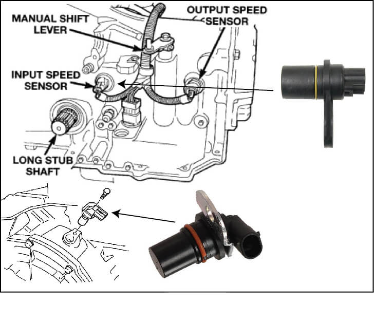
Physical Inspection and Electrical Testing of the Wiring Harness
Never assume the sensor itself is the culprit. Professional diagnostics always start with the physical wiring harness. The OSS sensor is located in a harsh environment, exposed to road debris, moisture, and extreme heat from the exhaust system.
📋
Professional Diagnostic Sequence
Inspect the connector for green corrosion (verdigris) or “spread” terminals. Check the loom for frayed insulation near exhaust manifold heat shields.
Use a Digital Multimeter (DMM) to check for continuity between the sensor connector and the TCM pins. Circuit resistance should be less than 0.5 ohms; anything higher indicates a quality issue in the wiring.
Perform a voltage drop test across the ground circuit while the system is powered. A high voltage drop on the ground side is a common cause of “phantom” OSS codes.
Expert Case Study: I recently diagnosed a truck with intermittent signal loss (P0721). The sensor was new, but the problem persisted. By back-probing the circuit while the engine was running, I discovered high electromagnetic interference (EMI) originating from an unshielded aftermarket alternator wire running parallel to the OSS harness. Separating the wires resolved the signal corruption immediately.
Repair Protocols and Replacing the Output Shaft Speed Sensor
When a sensor replacement is necessary, quality is the paramount factor. Utilizing an OEM-spec replacement sensor is vital because aftermarket units often vary in magnetic strength, which can lead to signal “dropout” at high speeds or temperature extremes.
Professional Installation Steps
- Clean the Mounting Surface: Use a lint-free cloth and brake cleaner to ensure the sensor seat is free of debris. Any debris can alter the air gap between the sensor tip and the reluctor wheel, causing a weak signal.
- Check the Reluctor Wheel: Before inserting the new sensor, peer into the mounting hole. Rotate the shaft to ensure no teeth are chipped or clogged with metallic shavings.
- Torque to Spec: Follow the manufacturer’s torque specification (usually 8-12 lb-ft). Over-tightening can crack the sensor body, while under-tightening leads to vibration-induced signal failure.
- Adaptive Relearn: This is the most overlooked step. After clearing the codes, you must perform a Transmission Adaptive Relearn.
Post-Repair Road Test Stats
Adaptive Learning Period
25%, 50%, 75% Throttle
Failure to perform an adaptive relearn can lead to continued harsh shifting for up to 50 miles while the TCM recalibrates. A professional road test should involve monitoring live Parameter IDs (PIDs) for OSS and ISS to ensure they track linearly during acceleration and deceleration.
Conclusion
The output shaft speed sensor circuit is vital for correct shift timing, speedometer operation, and cruise control. Effective diagnostics require a combination of OBD-II code analysis and physical electrical testing with a high-impedance multimeter to ensure circuit integrity. As we have explored, quality repairs depend on identifying whether the failure lies in the sensor itself or within the wiring harness, connectors, or even external electromagnetic interference. For those experiencing transmission irregularities, begin with a professional scan of the OSS circuit data to ensure a reliable and cost-effective repair solution. Restoring this critical circuit is the only way to guarantee the long-term health and performance of your modern powertrain.
Frequently Asked Questions
Can I drive with a faulty output shaft speed sensor circuit?
While the vehicle may still move, driving with a compromised OSS circuit is not recommended. The transmission will likely enter ‘Limp Mode,’ locking the vehicle into a single gear to prevent damage. This results in poor acceleration, high fuel consumption, and potential overheating of the transmission fluid, which could lead to expensive internal failures over time.
What is the difference between an OSS sensor and a VSS sensor?
The Output Shaft Speed (OSS) sensor measures the rotation of the transmission’s output shaft specifically for the TCM’s shifting logic. The Vehicle Speed Sensor (VSS) provides vehicle speed data primarily for the speedometer and cruise control. In many modern vehicles, the OSS signal is processed to provide the VSS data, effectively merging the two functions into one circuit.
How do I know if the sensor or the wiring is the problem?
An expert diagnosis involves testing the sensor’s internal resistance first. If the sensor meets manufacturer specifications, the focus shifts to the circuit wiring. Using a multimeter, you must check for 5V or 12V reference power and a solid ground at the connector. If power and ground are present but no signal reaches the PCM, the wiring harness is likely damaged.
Why does my speedometer stop working when the OSS circuit fails?
The speedometer relies on the pulses generated by the output shaft speed sensor to calculate road speed. If the circuit is broken or the signal is lost, the PCM or instrument cluster has no data to display. This is a common symptom in vehicles where the OSS circuit serves as the primary speed input for the entire vehicle communication network.
Does a faulty OSS circuit always trigger a Check Engine Light?
Yes, because the OSS circuit is critical for emissions and powertrain safety, the PCM will almost always trigger a Malfunction Indicator Lamp (MIL). You will typically find codes ranging from P0720 to P0723. In some cases, the ‘ABS’ or ‘Traction Control’ lights may also illuminate due to the loss of speed data required for those systems.