OBS 7.3 Fuel System Diagram: Diagnosis & Fix Guide
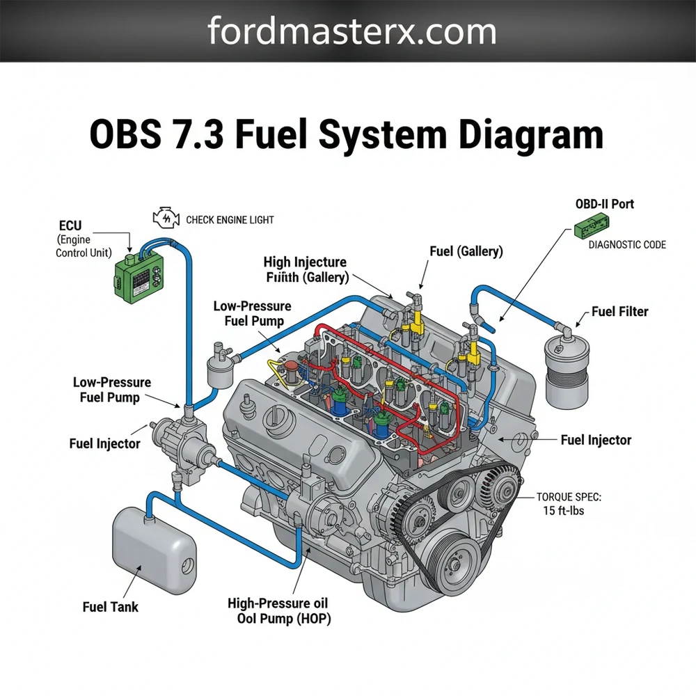
The OBS 7.3 fuel system diagram illustrates the fuel flow from the dual tanks, through the selector valve, to the mechanical lift pump, and finally into the fuel bowl and injectors. This layout helps owners pinpoint leaks, air intrusion, or pressure drops within the mechanical delivery and high-pressure oil circuits.
📌 Key Takeaways
- Visualizes fuel flow from the chassis tanks to the engine heads
- The mechanical lift pump and fuel bowl are the most critical components to identify
- Always bleed air from the fuel filter housing after opening the system
- Check fuel pressure at the Schrader valve on the fuel bowl
- Use this diagram when diagnosing hard starts, stalls, or power loss
Understanding the internal architecture of a classic Ford diesel requires more than just a general mechanical knowledge; it demands a specific mastery of the obs 7.3 fuel system diagram. For owners of the 1994.5 to 1997 Powerstroke, the fuel system is often the primary source of both legendary reliability and frustrating maintenance hurdles. This comprehensive guide is designed to deconstruct the complex web of lines, valves, and pumps located within the engine valley and chassis. By the end of this article, you will be able to identify every major component, understand the flow of diesel from the tank to the injectors, and use diagnostic patterns to keep your heavy-duty truck running at peak performance.
Decoding the OBS 7.3 Fuel System Diagram
The fuel system on an Old Body Style (OBS) 7.3L Powerstroke is a mechanical-transfer design, which distinguishes it significantly from the later Super Duty models that utilized electric pumps. The diagram represents a loop that begins at the dual fuel tanks and moves through a selector valve located on the frame rail. From there, fuel is pulled forward toward the engine by a cam-driven mechanical lift pump sitting deep in the “valley” of the engine block.
In a standard visual breakdown, the diagram highlights three distinct zones: the supply side, the pressurized side, and the return side. The supply side includes the pickup screens in the tanks and the hard lines running along the frame. The pressurized side is concentrated in the engine valley, where the mechanical pump pushes fuel into the fuel filter housing (often called the fuel bowl). Inside this bowl, the fuel is filtered and the pressure is regulated before being sent through steel lines into the cylinder heads. Finally, the return side carries excess fuel and air bubbles back to the tanks to maintain a cool, consistent flow.
Unlike modern engines where the ECU manages every micro-adjustment of fuel pressure via electronic sensors, the OBS 7.3 relies heavily on the mechanical health of the dual-stage pump and the spring-loaded pressure regulator (IPR) on the side of the fuel bowl. Variations in the diagram may occur depending on whether the truck is a California-spec model, which occasionally featured a dampener on the fuel lines to reduce noise, or if a previous owner has performed a “Stage 1” shim mod to the regulator.
The mechanical fuel pump on the OBS 7.3 is a “tandem” design. The bottom stage pulls fuel from the tanks at low pressure, while the top stage pushes it into the filter bowl and heads at high pressure (approximately 40-60 PSI).
[DIAGRAM_PLACEHOLDER: A technical schematic showing the fuel path from the rear and mid-ship tanks, through the selector valve, into the mechanical lift pump in the engine valley, through the fuel bowl/filter assembly, into the cylinder heads, and back through the return lines.]
How to Read and Apply the Fuel System Diagram

Interpreting an automotive diagram is the first step toward successful DIY repair. To use the obs 7.3 fuel system diagram effectively, you must treat it as a roadmap for pressure and vacuum. When the engine is cranking but not starting, the diagram tells you to look at the “suction” side of the pump first. If you have a “fuel in the valley” leak, the diagram points you toward the “high-pressure” seals on the pump or the fuel bowl drain valve.
- ✓ Step 1: Identify the Fuel Source – Locate the tank selector valve on the driver’s side frame rail. This is the starting point for all fuel flow.
- ✓ Step 2: Trace the Supply Line – Follow the larger diameter line from the valve up to the mechanical pump located behind the high-pressure oil pump (HPOP).
- ✓ Step 3: Inspect the Valley Components – Use the diagram to find the lines connecting the pump to the bottom of the fuel bowl. This is a common leak point.
- ✓ Step 4: Locate the Fuel Pressure Regulator (FPR) – This is situated on the side of the fuel bowl. The diagram shows the return line exiting from this point.
- ✓ Step 5: Verify Head Feed Lines – Two steel lines exit the fuel bowl and enter the front of the driver-side head and the rear of the passenger-side head.
- ✓ Step 6: Track the Return Path – Follow the smaller diameter lines back from the heads and the FPR to the selector valve and ultimately back to the tanks.
When working on these components, safety is paramount. Diesel fuel is a solvent and can degrade rubber quickly. Always use nitrile gloves and ensure the engine is cool. Unlike gasoline engines that use a timing chain, the 7.3L Powerstroke uses a gear-driven system, meaning you don’t have to worry about skipping timing while working near the front of the engine, but you must be careful not to drop debris into the pump’s mounting hole in the block.
Before removing the mechanical fuel pump, ensure the area is clean. If the plunger or any debris falls into the engine through the pump hole, it can cause catastrophic internal damage to the cam gear.
Common Issues and Troubleshooting

The OBS fuel system is prone to a few specific failures that the diagram can help you isolate. One of the most common issues is air infiltration. If the pickup screens in the fuel tanks break off (a common “Showerhead” failure), the system will suck air when the tank is below 1/4 full. By referring to the diagram, you can see that any air introduced at the tank will travel through the entire system, causing erratic idling and a check engine light if the injection control pressure begins to fluctuate wildly.
Another frequent problem is a clogged fuel pressure regulator screen. Located inside the fuel bowl, this tiny screen can become blocked with debris. This restriction causes a diagnostic code related to low fuel pressure or poor performance. While the OBS 7.3 has limited OBD-II capabilities compared to modern trucks, a scan tool can still reveal codes that point toward fuel delivery inconsistencies. If you notice fuel pooling in the engine valley, the diagram helps you distinguish between a leaking fuel bowl drain valve (yellow handle) and a weeping mechanical pump weep hole.
Maintenance Tips and Best Practices
To keep your 7.3L Powerstroke running for another 300,000 miles, proactive maintenance is essential. The fuel filter should be replaced every 15,000 miles. When doing so, inspect the fuel bowl for “black slime,” which indicates a bacterial growth in the diesel that can clog the sensitive injectors.
When reinstalling the fuel bowl or the mechanical pump, always adhere to the torque spec of 30-35 lb-ft for the mounting bolts. Over-tightening can crack the housing, while under-tightening will lead to leaks in the high-vibration environment of a diesel engine.
If you find yourself frequently repairing the mechanical pump, consider an “E-fuel” conversion. This modification replaces the mechanical pump and fuel bowl with an electric pump and spin-on filters. This simplifies the obs 7.3 fuel system diagram significantly, removing the cam-driven pump from the valley and providing a more consistent fuel pressure that improves throttle response and cold starts.
When performing any top-end work, it is often necessary to remove the accessory belt and some components of the coolant flow system, such as the upper radiator hose, to gain enough clearance to reach the fuel lines at the back of the heads. Always check your hoses for rubbing or fraying while you have the system apart. High-quality Viton O-rings are highly recommended for any fuel system repairs, as they resist the corrosive properties of modern ultra-low sulfur diesel (ULSD) better than standard rubber.
By mastering the layout and logic of the fuel system, you transform from a frustrated owner into a capable technician. Whether you are chasing a diagnostic code or simply performing a routine filter change, let the diagram be your definitive guide to the heartbeat of your 7.3L Powerstroke.
Step-by-Step Guide to Understanding the Obs 7.3 Fuel System Diagram: Diagnosis & Fix Guide
Identify the supply and return lines coming from the fuel tanks to the selector valve.
Locate the mechanical fuel pump situated in the engine valley behind the fuel bowl.
Understand how the two-stage pump draws fuel from the tanks and pushes it into the filter.
Connect a mechanical pressure gauge to the fuel bowl to verify the pump is meeting 40-60 PSI.
Verify that the ECU isn’t throwing a diagnostic code by checking the system with a compatible scanner.
Complete the repair by tightening all fittings to the specific torque spec to prevent leaks.
Frequently Asked Questions
Where is the fuel filter bowl located?
The fuel filter bowl on an OBS 7.3 Powerstroke is located directly on top of the engine, centered in the ‘valley’ between the cylinder heads. It is easily identifiable by its large black plastic cap and sits just behind the high-pressure oil pump (HPOP) and in front of the turbocharger.
What does the OBS 7.3 fuel system diagram show?
The diagram shows the entire path of diesel fuel starting from the front and rear tanks. It maps the lines leading to the fuel selector valve, the mechanical lift pump located in the engine valley, the fuel filter housing, and finally the supply lines feeding the two cylinder heads.
How many fuel lines connect to the mechanical pump?
The standard OBS 7.3 mechanical fuel pump features two stages and connects to four distinct lines. These include the main suction line from the chassis, a high-pressure feed to the fuel bowl, and return lines that manage excess fuel and air back to the fuel tank via the selector valve.
What are the symptoms of a bad fuel system?
Common symptoms include long cranking times, a stuttering engine under load, or a check engine light. If the ECU detects low pressure or timing issues, it may trigger a diagnostic code. You can use a scanner on the port to check for codes related to fuel delivery or injection pressure.
Can I install an electric fuel conversion myself?
Yes, many owners replace the mechanical pump with an electric ‘e-fuel’ system. This involves removing the mechanical pump from the valley, installing a block-off plate, and mounting an electric pump and filters on the frame rail. It significantly improves reliability and makes filter changes much easier for DIY mechanics.
What tools do I need for fuel system repairs?
You will need a set of flare nut wrenches for the fuel lines, a socket set with extensions for the fuel bowl mounting bolts, and a fuel pressure gauge. Additionally, a torque wrench is essential to ensure all fittings and the fuel pump mounting bolts meet the factory torque spec.


