Mustang 2 Rack and Pinion Hose Diagram: Easy Setup Guide
The Mustang 2 rack and pinion hose diagram identifies the high-pressure port, typically closer to the input shaft, and the low-pressure return port. Proper routing ensures the steering pump functions correctly alongside other systems like auxiliary power, providing the necessary control when towing or using an RV blade connection.
📌 Key Takeaways
- Distinguish between the high-pressure feed and the low-pressure return lines
- The pressure port is usually the smaller of the two fittings on the rack
- Ensure hose clearance from exhaust heat to prevent steering failure
- Match the pump output pressure to the rack requirements for safety
- Use this diagram when converting a classic vehicle to power steering
Navigating the complexities of custom vehicle builds requires a mastery of both fluid dynamics and electrical systems. Whether you are currently plumbing a mustang 2 rack and pinion hose diagram for your front-end swap or finishing the electrical interface for your car hauler, understanding the schematics is the difference between a reliable ride and a roadside breakdown. This guide focuses on the critical 7-way RV blade trailer wiring system, a standard for anyone transporting a project car. You will learn how to identify every pin, interpret color codes, and integrate advanced features like electric brakes and auxiliary power to ensure your towing setup is as high-performing as the vehicle on the trailer.
While a mustang 2 rack and pinion hose diagram handles hydraulic pressure for steering, a trailer wiring diagram manages the electrical current for safety and signaling. Both require precise routing to prevent interference with moving parts or heat sources.
Decoding the 7-Way RV Blade Trailer Diagram
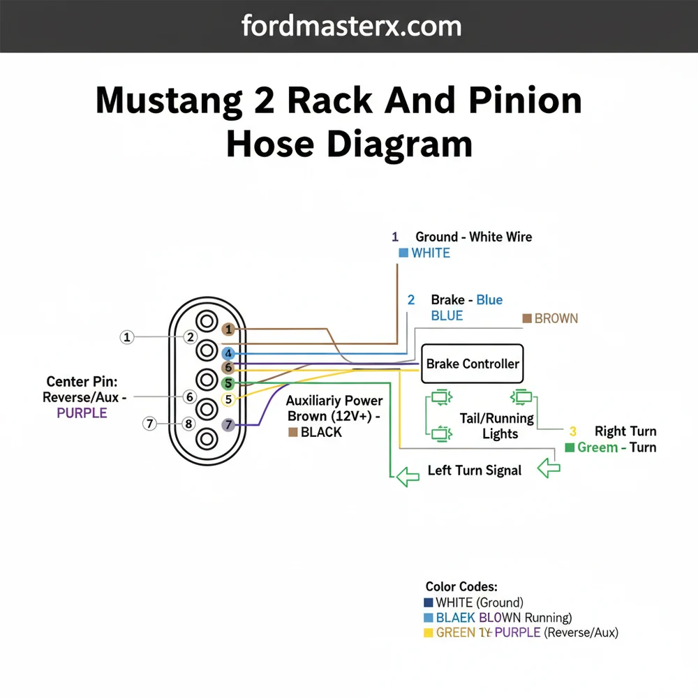
The 7-way RV blade connector is the gold standard for modern towing, providing more functionality than the basic 4-pole flat connector. Unlike the simpler versions that only manage basic lighting, the 7-way system integrates a brake controller, reverse lights, and a dedicated battery charge line. When looking at the diagram, you are typically viewing the face of the vehicle-side socket or the rear of the trailer-side plug.
The visual breakdown of the pins follows a specific circular orientation. At the center of the diagram is the reverse light circuit, typically coded in purple. Moving clockwise from the top, you will find the auxiliary power (black), which provides 12V constant power to the trailer battery. Following this is the right turn signal and brake light (green). At the bottom of the circle sits the electric brake signal (blue), which carries the modulated voltage from the cabin’s brake controller.
The remaining pins include the ground pin (white) at the seven o’clock position, which is the most critical connection for the entire system. At nine o’clock is the left turn signal and brake (yellow), and at eleven o’clock are the tail and running lights (brown). This standardized layout ensures that any truck equipped with a 7-way hitch can pull any trailer with a matching plug, provided the wiring follows this universal map.
[DIAGRAM_PLACEHOLDER: 7-Way RV Blade Connector Pinout showing: Center: Reverse (Purple), 1:00: Battery (Black), 3:00: Right Turn (Green), 5:00: Electric Brakes (Blue), 7:00: Ground (White), 9:00: Left Turn (Yellow), 11:00: Running Lights (Brown)]
Step-by-Step Guide to Reading and Implementing the Diagram

Interpreting a trailer wiring diagram is remarkably similar to following a mustang 2 rack and pinion hose diagram; you are essentially mapping a path from the source to the destination while ensuring no leaks—whether hydraulic or electrical—occur along the way. Follow these steps to wire or repair your 7-way system correctly.
- ✓ Step 1: Identify Your Connector Type – Ensure you are working with an RV blade style rather than a round-pin heavy-duty commercial plug. While they look similar, the pin assignments and physical shapes are incompatible.
- ✓ Step 2: Establish a Solid Ground – Before connecting any power lines, the ground pin (white wire) must be secured to the trailer frame. Use a self-tapping screw and a star washer to bite into the metal. A weak ground is the primary cause of dim running lights and “ghost” signals.
- ✓ Step 3: Wire the Running Lights – Connect the brown wire to the tail light circuit. This circuit powers all side markers and the rear identification lights. Ensure the wire gauge is sufficient to handle the total number of bulbs on the trailer.
- ✓ Step 4: Connect Turn and Brake Signals – The yellow (left) and green (right) wires carry dual signals. In modern vehicles, these are combined. When you apply the brakes, both wires receive power; when you use a turn signal, only one flashes.
- ✓ Step 5: Integrate the Brake Controller – The blue wire is the “muscle” of the system. It connects to the electric brake magnets on the trailer axles. This wire should be at least 12-gauge to prevent voltage drop over long distances.
- ✓ Step 6: Activate Auxiliary Power – Connect the black wire to the vehicle’s battery through a 30-amp circuit breaker. This allows the trailer to charge its breakaway battery or power internal lights while the vehicle is running.
- ✓ Step 7: Final Verification – Use a multimeter or a 7-way circuit tester. Check each function (Left Turn, Right Turn, Brakes, Reverse) individually to ensure there is no cross-talk between pins.
When wiring the plug, apply a small amount of dielectric grease to the terminals. This prevents corrosion from road salt and moisture, which is the leading cause of electrical failure in trailers.
Common Issues & Troubleshooting

Even with a perfect mustang 2 rack and pinion hose diagram and a clean wiring setup, issues can arise due to the harsh environment trailers inhabit. The most common symptom is flickering running lights or a brake controller that intermittently loses connection. These issues are almost always related to the ground pin. If the ground is weak, the electricity will try to find a path back to the truck through the hitch ball, which is an unreliable connection.
Another frequent problem is the “trailer disconnected” warning on the truck dashboard. This usually indicates a break in the blue electric brake wire or a blown fuse in the vehicle’s auxiliary power circuit. If your turn signals work but your brake lights do not, or vice-versa, the issue likely lies within the vehicle-side logic module rather than the trailer wiring itself.
Never test trailer wires by touching them to the trailer frame to see if they spark. This can fry modern vehicle ECUs or damage sensitive brake controller electronics. Always use a digital multimeter.
Tips & Best Practices for Long-Term Reliability
To ensure your trailer wiring lasts as long as your vehicle, prioritize quality components. When transitioning from a standard 4-way flat connector to a 7-way RV blade, use a pre-molded harness. These are factory-sealed to prevent water from entering the back of the plug where the wires are screwed into the terminals.
For those building custom chassis where a mustang 2 rack and pinion hose diagram is being utilized, space is often at a premium. Route your electrical wires through the frame rails where possible, but use rubber grommets at every entry and exit point to prevent the metal from chafing the insulation.
Maintenance is equally important. Periodically inspect the 7-way plug for green oxidation. If you find any, clean it with an electrical contact cleaner and a small wire brush. Additionally, if your trailer uses electric brakes, ensure the magnets are adjusted correctly so they don’t draw excessive amperage, which can overheat the wiring.
- ✓ Use heat-shrink butt connectors for all splices; never use twist-on wire nuts or electrical tape alone.
- ✓ Upgrade to LED trailer lights to reduce the load on your auxiliary power and running light circuits.
- ✓ Label your wires at both ends of the trailer for easier future troubleshooting.
In conclusion, whether you are meticulously following a mustang 2 rack and pinion hose diagram for your custom steering setup or mapping out the ground pin and brake controller for your trailer, technical accuracy is paramount. By understanding the 7-way RV blade diagram and following a structured installation process, you ensure that your vehicle and trailer function as a cohesive, safe unit on the road. Proper grounding, weatherproofing, and regular maintenance are the keys to a trouble-free towing experience.
Frequently Asked Questions
Where is the pressure port located?
On a Mustang 2 rack and pinion, the pressure port is located on the valve housing, generally positioned closer to the steering input shaft. It is often the smaller threaded hole, typically 9/16-18 or M14, depending on whether the rack is an original Ford unit or a modern aftermarket version.
What does this hose diagram show?
This diagram illustrates the flow of power steering fluid from the pump reservoir to the rack and back. It highlights the high-pressure line that provides steering assistance and the low-pressure return line, ensuring the system integrates with other chassis components like the auxiliary power circuit and brake controller wiring.
How many connections does the Mustang 2 rack have?
A standard Mustang 2 rack and pinion has two main fluid connections: the high-pressure inlet and the low-pressure return. While the rack handles steering, the vehicle’s electrical system separately manages the RV blade plug for running lights, turn signals, and the brake controller for safe trailer operation during transit.
What are the symptoms of a bad hose?
Symptoms include visible fluid leaks at the fittings, a whining noise from the pump due to air ingestion, or a sudden loss of steering assist. If your turn signal or running lights work but steering is stiff, check the pressure hose for kinks or internal collapses that restrict fluid flow.
Can I install these hoses myself?
Yes, installing these hoses is a standard DIY task. You must ensure the threads match and use a flare nut wrench to avoid stripping the fittings. It is also a good time to verify that your auxiliary power and trailer wiring are safely routed away from the moving steering components.
What tools do I need for this task?
You will need a set of SAE or metric flare nut wrenches, a drain pan for old fluid, and new power steering fluid. Additionally, if you are also setting up a trailer connection, you may need a multimeter to test the RV blade pins for running lights and turn signal functionality.


