Motorcraft 2 Barrel Carburetor Diagram: Complete Guide
A Motorcraft 2 barrel carburetor diagram illustrates the internal and external components, including the venturi, float bowl, and throttle plates. It serves as a visual map for fuel flow and vacuum routing, helping you identify crucial parts like the accelerator pump and power valve for tuning or rebuilds.
📌 Key Takeaways
- Identifies internal fuel passages and vacuum port locations
- The float and needle seat are critical for fuel level management
- Always check for a flat mounting surface to avoid vacuum leaks
- Use the diagram to verify the correct installation of the power valve
- Essential for servicing Ford 2100 and 2150 series carburetors
Understanding the internal mechanics of your vehicle’s fuel delivery system is a fundamental skill for any classic car enthusiast or DIY mechanic. In this comprehensive guide, we provide a detailed analysis of the motorcraft 2 barrel carburetor diagram, specifically focusing on the ubiquitous 2100 and 2150 models. You will learn how to identify every critical component, interpret exploded views for a successful rebuild, and troubleshoot performance bottlenecks. Having an accurate diagram is essential because even a minor misalignment of a needle or a misplaced gasket can lead to poor engine performance or total failure. By the end of this article, you will be equipped with the technical knowledge to navigate the complexities of these legendary carburetors, ensuring your engine runs smoothly and efficiently.
Decoding the Motorcraft 2 Barrel Carburetor Diagram
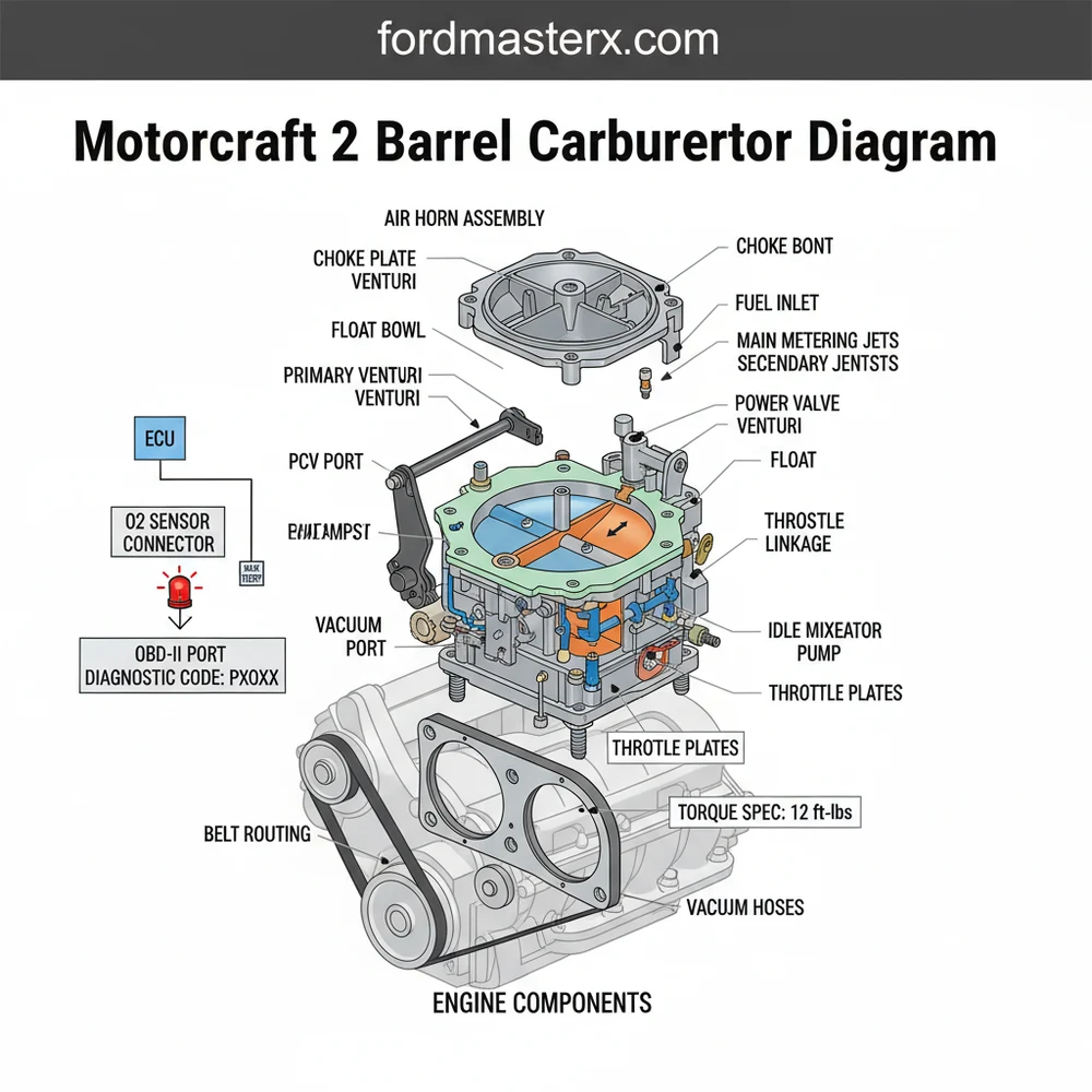
The motorcraft 2 barrel carburetor diagram serves as a blueprint for the mechanical heart of your engine. These carburetors, primarily the 2100 and 2150 series, are prized for their simplicity and reliability. When you look at a primary diagram, you are seeing a multi-layered representation of three main sections: the air horn (the top lid), the main body (the center housing), and the throttle body (the base). Each section is populated with specific components that must work in perfect harmony to balance the air-fuel ratio.
(A) Air Horn Assembly
|– Choke Plate
|– Venturi Cluster
(B) Main Body
|– Float & Needle Seat
|– Main Jets
|– Accelerator Pump
|– Power Valve (Bottom)
(C) Throttle Body
|– Throttle Plates
|– Idle Mixture Screws
|– Base Gasket
Figure 1: Conceptual breakdown of the Motorcraft 2-barrel architecture.
The diagram highlights several key elements. At the very top, the choke plate controls the initial air intake during cold starts. Moving deeper, the venturi cluster is responsible for creating the pressure drop that pulls fuel from the bowl. A critical area often highlighted in these diagrams is the float bowl. Here, a mechanical float monitors the fuel level, similar to a toilet tank valve. If the diagram shows a 2150 model, you will likely see an additional component known as the altitude compensator, which is a bellows-like device that adjusts the mixture based on atmospheric pressure.
Color-coding in modern digital diagrams often separates the fuel circuit (typically blue or green) from the air circuit (typically red or orange). This visual distinction is vital when tracing vacuum leaks or clogs. You will also notice the accelerator pump housing on the front of the main body. This mechanical pump provides an extra squirt of fuel when you suddenly depress the gas pedal, preventing the engine from stumbling. Understanding these spatial relationships via the motorcraft 2 barrel carburetor diagram is the first step toward a successful diagnostic or restoration project.
Step-by-Step Guide to Using the Diagram for Maintenance
Interpreting a motorcraft 2 barrel carburetor diagram requires a systematic approach. Whether you are performing a basic cleaning or a full rebuild, following these steps will ensure you do not lose your way among the many springs, clips, and gaskets.
Before beginning work, always ensure the engine is cool. Unlike modern vehicles with an ECU that handles adjustments, carburetors are purely mechanical and require manual precision.
- Component Identification: Lay your carburetor on a clean workspace and compare it to the diagram. Identify the primary external linkages, such as the choke pull-down and the throttle return spring. This helps you understand how the external movement translates to internal changes.
- Preparation and Tools: Gather the necessary tools identified by the diagram’s fastener types. You will typically need a set of flat-head screwdrivers, a 5/16-inch nut driver, and needle-nose pliers. Ensure you have a specialized carburetor cleaner and a container for small parts.
- Controlled Disassembly: Following the numerical sequence often provided in a rebuild kit’s diagram, begin removing the air horn screws. As you lift the top off, pay close attention to the float pin and the tiny “bails” or clips that hold the needle in place. Refer to the diagram to see exactly how the float hinge should be oriented.
- Cleaning the Orifices: Use the diagram to locate the main jets and the idle air bleeds. These are tiny holes that can easily become clogged with varnish. Use compressed air and cleaner to ensure every passage shown on the diagram is clear. Never use a wire to poke through jets, as this can change their diameter and ruin the fuel calibration.
- The Power Valve Check: Located at the bottom of the main body, the power valve is a common failure point. The diagram will show a cover plate with four screws. Remove this and inspect the diaphragm. If it is ruptured, your engine will run excessively rich.
- Reassembly and Torque Spec: When putting the units back together, refer to the diagram for gasket placement. It is crucial to follow the recommended torque spec for the base bolts and the air horn screws. Over-tightening can warp the soft aluminum or zinc castings, leading to permanent vacuum leaks.
- Bench Adjustments: Before installing the unit back on the engine, use the diagram’s specifications to set the float level. This is usually measured from the top of the bowl to the top of the float. Adjusting this now prevents the need to take the carburetor apart again later.
- Safety Synchronization: Once reinstalled, ensure the accessory belt is clear of any tools and that the timing chain is correctly synchronized with your ignition timing. A carburetor cannot be properly tuned if the mechanical timing of the engine is off.
Gasoline is highly flammable. Always work in a well-ventilated area and keep a fire extinguisher nearby. Do not smoke or create sparks while the fuel bowl is open.
Common Issues and Troubleshooting

While modern cars use an OBD-II system to provide a diagnostic code when something goes wrong, a Motorcraft carburetor requires “ear and nose” diagnostics. If your check engine light were a physical sensation, it would be the smell of raw fuel or the sound of a backfire. The motorcraft 2 barrel carburetor diagram is your primary tool for solving these mechanical “codes.”
One of the most frequent problems is a “stumble” during acceleration. By looking at the diagram, you can trace this to the accelerator pump circuit. If the diaphragm is cracked or the check ball is stuck, the engine won’t get the fuel it needs when the throttle opens. Another common issue is a rough idle. The diagram points you to the idle mixture screws at the base. If adjusting these doesn’t help, you likely have a vacuum leak at the base gasket or a clogged idle passage.
If the engine floods or stalls, the diagram helps you locate the float and needle valve. A heavy, fuel-soaked float will sink, causing the needle to stay open and overflow the bowl. By referencing the diagram, you can quickly identify these parts for replacement without having to guess which screw does what.
Pro Tips and Best Practices
To keep your Motorcraft 2-barrel carburetor in top condition, maintenance is key. Unlike an ECU-controlled system that adapts to changes, a carburetor is a “set it and forget it” device that requires seasonal check-ups. Here are several pro tips to ensure longevity and performance:
- ✓ Monitor Coolant Flow: Many Motorcraft carburetors use a thermostatic choke that relies on coolant flow through a spacer or a heater hose. Ensure these lines are clear; otherwise, your choke will never fully open, causing poor gas mileage and carbon buildup.
- ✓ Fuel Filtration: Install a high-quality in-line fuel filter before the carburetor. Small particles can easily clog the fine passages shown in your motorcraft 2 barrel carburetor diagram.
- ✓ Use Genuine Gaskets: When rebuilding, avoid “universal” gasket sets. Use components designed specifically for the 2100 or 2150 to ensure vacuum ports align perfectly with the main body passages.
- ✓ Check Mechanical Timing: A carburetor’s performance is intrinsically linked to the timing chain health. If your chain is stretched, no amount of carburetor tuning will fix a rough-running engine.
If you are struggling with a persistent rich condition, check the power valve first. Many mechanics replace the entire carburetor when a simple $10 power valve replacement would have solved the issue.
In conclusion, the motorcraft 2 barrel carburetor diagram is more than just a piece of paper; it is a vital diagnostic instrument. By understanding how the air horn, main body, and throttle assembly interact, you can bypass the need for expensive shop visits. While modern technicians rely on an OBD-II scanner to read a diagnostic code, you will have the satisfaction of tuning your engine by hand, ensuring that every horse-power is accounted for and every drop of fuel is used efficiently.
Frequently Asked Questions
Where is the idle mixture screw located?
The idle mixture screws are located at the base of the carburetor on the front side. On the Motorcraft 2 barrel carburetor, adjusting these screws controls the air-to-fuel ratio at idle. They are usually accessible without removing the air cleaner, though some models have limiter caps.
What does a Motorcraft 2 barrel carburetor diagram show?
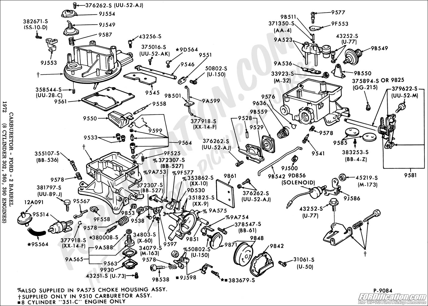
The diagram provides an exploded view of all internal and external parts, including the choke housing, venturi clusters, and the accelerator pump assembly. It details how the throttle linkages connect to the internal plates and highlights the positioning of gaskets and seals required for a leak-free rebuild.
What is the mounting torque spec for this carburetor?
The typical mounting torque spec for a Motorcraft 2 barrel carburetor is between 12 to 15 foot-pounds. It is vital to tighten the mounting nuts evenly in a cross pattern to prevent warping the base plate, which is a common cause of persistent engine vacuum leaks.
What are the symptoms of a bad carburetor?
Symptoms include rough idling, stalling, and poor acceleration. Unlike modern vehicles with an ECU and OBD-II, these mechanical systems won’t trigger a check engine light or store a diagnostic code. You must rely on manual inspection and the diagram to identify clogged jets or a failing power valve.
Can I rebuild this carburetor myself?
Yes, rebuilding a Motorcraft 2100 or 2150 is a manageable DIY project. By following the diagram and using a high-quality rebuild kit, you can replace worn gaskets, the accelerator pump diaphragm, and the power valve. Ensure you work in a clean area to prevent debris from entering passages.
What tools do I need for carburetor service?
You will need basic hand tools including flat-head and Phillips screwdrivers, a socket set, and a pair of needle-nose pliers. Additionally, keep a can of carburetor cleaner, a soft-bristled brush, and a can of compressed air ready to clear out the small internal passages shown in the diagram.