Intake Manifold Ford 4.2 Liter V6 Engine Diagram Guide
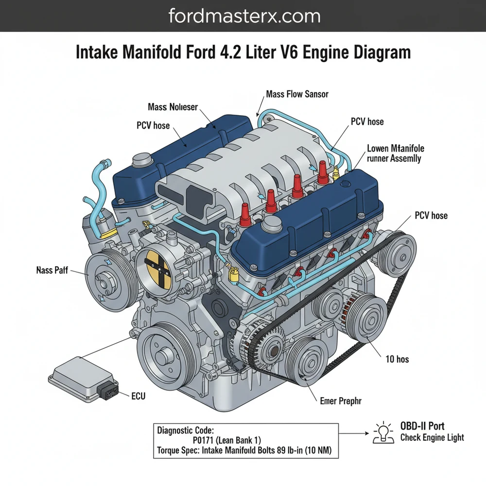
The intake manifold Ford 4.2 liter V6 engine diagram illustrates the upper plenum, lower intake runners, and the IMRC system. It identifies critical components like isolator bolts and gaskets that frequently cause a check engine light. Using this map ensures correct vacuum line routing and proper seating to prevent lean air-fuel mixtures.
📌 Key Takeaways
- Visualizes the split-port induction system unique to the Ford 4.2L V6
- Identifies the IMRC (Intake Manifold Runner Control) linkages and bushings
- Highlights common leak points that trigger lean diagnostic codes
- Provides the necessary torque spec sequence for leak-free reassembly
- Assists in routing complex vacuum lines back to the throttle body
If you are performing a top-end engine tear-down or diagnosing a persistent lean condition on your Ford truck or van, having a clear intake manifold ford 4.2 liter v6 engine diagram is an absolute necessity. The 4.2L Essex V6 engine, widely used in the F-150 and E-Series vehicles, features a complex two-piece intake manifold design that is critical for managing air-fuel ratios and engine efficiency. This guide provides a detailed breakdown of the manifold’s architecture, from the upper plenum to the lower runner controls, ensuring you can identify every vacuum port, sensor location, and gasket interface required for a successful repair or maintenance project.
Understanding the Ford 4.2 Liter V6 Intake Manifold Layout
The intake system on the Ford 4.2L V6 is divided into two primary sections: the upper intake manifold (often called the plenum) and the lower intake manifold. The upper manifold is typically constructed of reinforced plastic or composite material, designed to streamline airflow from the throttle body into the individual runners. A high-quality intake manifold ford 4.2 liter v6 engine diagram will show the throttle body mounting flange at the front, with various vacuum ports distributed along the sides for the brake booster, PCV system, and EVAP canister purge valve.
The lower intake manifold is a cast aluminum component that sits directly in the “V” of the engine block. This part is responsible for distributing air into the cylinder heads and houses the fuel injectors and fuel rail. One of the most unique features of this engine’s manifold is the Intake Manifold Runner Control (IMRC) system. The diagram highlights the IMRC actuators located at the rear of the manifold, which operate butterfly valves within the runners to optimize torque at low RPMs and horsepower at high RPMs. Furthermore, the lower manifold serves as a bridge for coolant flow between the cylinder heads, featuring a coolant crossover passage and the thermostat housing mount.
In the diagram, you will notice several electrical connections. These lead to the ECU (Engine Control Unit), which monitors air intake temperature and pressure. The upper manifold houses the Intake Air Temperature (IAT) sensor and provides a mounting point for the Idle Air Control (IAC) valve. Understanding these connections is vital because any leak in the gaskets between the upper and lower sections can lead to significant performance issues and triggered fault codes.
[DIAGRAM_PLACEHOLDER: Detailed schematic of Ford 4.2L V6 Intake Manifold showing Upper Plenum, Lower Manifold, IMRC Actuators, Fuel Rail, and Gasket Interfaces]
Step-by-Step Guide to Using the Diagram for Component Removal
Navigating a repair on the 4.2L V6 requires a methodical approach. By following the spatial relationships shown in your intake manifold ford 4.2 liter v6 engine diagram, you can avoid common pitfalls such as breaking fragile vacuum lines or stripping manifold bolts.
Always relieve fuel system pressure before disconnecting the fuel rail from the lower intake manifold. Failure to do so can result in fuel spray and a potential fire hazard.
- ✓ Step 1: Preparation and Cooling. Ensure the engine is completely cool. Disconnect the negative battery terminal to prevent electrical shorts while working near the ECU wiring harness. Drain the engine coolant to a level below the intake manifold to prevent fluid from entering the cylinders during removal.
- ✓ Step 2: Clear the Accessory Path. Remove the air intake duct and the accessory belt. In many configurations, you may need to loosen the alternator bracket to gain full access to the front manifold bolts as indicated in your diagram.
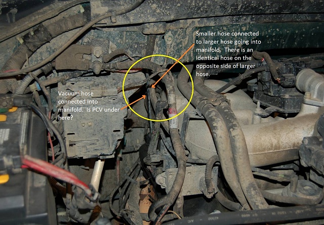
- ✓ Step 3: Disconnect Sensors and Vacuum Lines. Using the diagram as a map, label and disconnect the electrical connectors for the IAC valve, TPS (Throttle Position Sensor), and IAT sensor. Carefully remove the vacuum lines, paying close attention to the hard plastic lines that become brittle over time.
- ✓ Step 4: Upper Plenum Removal. Unbolt the upper intake manifold. This section is held by several “isolator bolts” which are a known weak point on the 4.2L engine. Once the bolts are loose, lift the plenum straight up to reveal the lower manifold and the IMRC linkage.
- ✓ Step 5: Lower Manifold and Fuel Rail. Disconnect the fuel injectors and remove the fuel rail. You can then unbolt the lower intake manifold. Note the location of the coolant flow passages in the diagram to ensure you don’t drop debris into the cooling system.
- ✓ Step 6: Cleaning and Inspection. Clean all mating surfaces on the cylinder heads and manifold sections. Check the timing chain cover area for any signs of oil leaks while the top end is disassembled.
- ✓ Step 7: Installation and Torque. Reinstall the lower manifold with new gaskets. Following the specific torque spec is critical: typically, the lower manifold bolts require a multi-stage torque sequence, ending at approximately 15-22 lb-ft, while the upper plenum isolator bolts are much lower, around 89 lb-in.
The Ford 4.2L V6 uses specialized “isolator bolts” for the upper intake. These bolts have rubber grommets that degrade, causing vacuum leaks. Always replace these bolts when removing the upper plenum to ensure a proper seal.
Common Issues and Troubleshooting

The primary reason most owners search for an intake manifold ford 4.2 liter v6 engine diagram is to troubleshoot a “Check Engine Light.” On this specific engine, the most frequent diagnostic code results are P0171 and P0174, which indicate that the engine is running lean on Banks 1 and 2.
When you see these codes on your OBD-II scanner, the diagram helps you pinpoint the likely culprits. The rubber grommets on the upper manifold isolator bolts frequently shrink, allowing “unmetered air” to enter the engine behind the throttle body. Additionally, the IMRC bushings at the back of the manifold are prone to cracking or falling out. If the linkage shown in the diagram is disconnected, the ECU will detect that the runner valves are not in the commanded position, leading to poor idle quality and a loss of power at higher speeds.
If you notice coolant disappearing without a visible leak on the ground, the lower intake manifold gasket may have failed near the coolant flow ports. This can cause coolant to leak into the intake ports or mix with the oil. Consult the diagram to identify the crossover points where the manifold meets the cylinder heads, as these are the high-stress areas most likely to fail.
Tips and Best Practices for Maintenance
To ensure the longevity of your Ford 4.2L V6, maintenance of the intake system is paramount. When performing any work involving the intake manifold ford 4.2 liter v6 engine diagram, consider these professional recommendations:
While the intake manifold is removed, it is the perfect time to inspect your spark plug wires and the heater hose return line. These components are much easier to reach with the plenum out of the way, saving you hours of labor later.
First, always use high-quality, updated gaskets. Ford released revised gaskets and isolator bolts specifically to address the lean-code issues common in earlier versions of this engine. Second, keep the IMRC linkages clean. A small amount of carbon buildup can cause the butterfly valves to stick, which puts strain on the actuators.
Furthermore, pay attention to the health of your accessory belt and pulleys while the intake is apart. Since you have to remove several components to reach the manifold, checking for play in the water pump or alternator at this stage is a smart preventative measure. Finally, while the intake manifold itself does not house the timing chain, the 4.2L is an overhead valve engine with a cam-in-block design. Keeping the intake sealed prevents contaminants from entering the lifter valley, which directly protects the internal timing components and oiling system.
By utilizing a detailed intake manifold ford 4.2 liter v6 engine diagram and following a disciplined repair process, you can keep your Essex V6 running smoothly for hundreds of thousands of miles. Whether you are clearing a diagnostic code or performing a routine gasket change, understanding the intricacies of air delivery and sensor placement is the key to automotive success.
Frequently Asked Questions
Where is the IMRC actuator located?
The IMRC actuator is located at the rear of the intake manifold, nestled near the firewall. On the Ford 4.2L V6 engine diagram, you can see it controls the runner butterflies. Accessing this area often requires removing the upper plenum to inspect the plastic bushings which frequently fail and trigger codes.
What does this intake manifold diagram show?
This diagram shows the complete assembly of the upper and lower intake manifolds, including vacuum port locations, sensor mounting points, and the fuel rail interface. It serves as a visual guide for identifying where unmetered air might enter the system, causing the ECU to struggle with maintaining the correct idle.
What is the torque spec for the intake manifold bolts?
For the Ford 4.2L V6, the upper intake manifold bolts typically require a torque spec of 89 lb-in. It is vital to follow the specific crisscross pattern shown in the diagram to ensure even pressure. Over-tightening can crack the plastic plenum, while under-tightening leads to persistent vacuum leaks.
What are the symptoms of a bad intake manifold?
Common symptoms include a rough idle, stalling, and a check engine light displaying P0171 or P0174 diagnostic codes. These lean codes indicate that the ECU has detected too much oxygen, often due to degraded isolator bolts or gaskets within the manifold assembly identified in our technical engine diagram.
Can I replace the intake manifold myself?
Replacing the upper intake manifold is a standard DIY project that takes about 3-4 hours. By following the diagram, you can accurately disconnect sensors and vacuum lines. However, be cautious when working near the fuel injectors on the lower manifold to avoid debris falling into the engine cylinders.
What tools do I need for this manifold project?
You will need a 1/4-inch drive socket set with 8mm and 10mm sockets, an inch-pound torque wrench, and an OBD-II scanner to clear codes. Pliers are necessary for spring-style hose clamps, and a shop vac is recommended to clean the engine valley before removing the lower manifold assembly.


