Inline 6 Ford 4.9 Engine Diagram: Repair & Component Guide
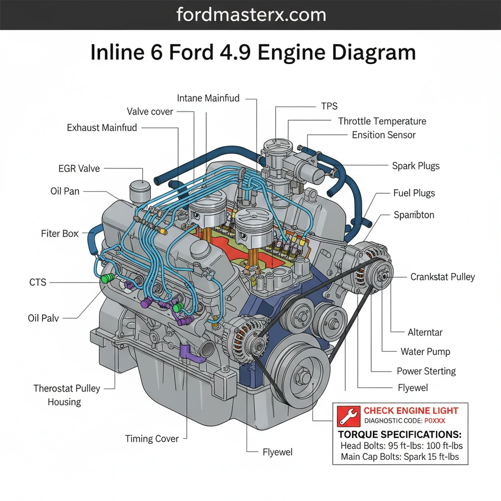
The inline 6 Ford 4.9 engine diagram provides a comprehensive layout of the 300 cubic inch powerhouse, including fuel injection components, ignition systems, and sensor locations. It identifies key parts like the distributor, intake manifold, and throttle body, allowing owners to trace wiring or vacuum leaks efficiently for better engine performance.
📌 Key Takeaways
- Primary map for Ford 300 I6 component layout
- Most important to identify the intake manifold and fuel rail
- Always verify vacuum line routing for idle stability
- Use diagrams to locate sensors like the MAP or TPS
- Essential for restoration and electrical diagnostics
The Ford 4.9-liter, better known as the 300 cubic inch Inline-6, is widely regarded as one of the most durable and reliable engines ever produced by the Ford Motor Company. Produced between 1965 and 1996, this engine powered everything from F-Series pickup trucks to industrial generators and UPS delivery vans. For the DIY enthusiast, the 300 Inline-6 is a dream to work on because of its spacious engine bay, straightforward design, and gear-driven timing. However, understanding the specific layout and “reading” the engine diagram is essential for successful repairs, whether you are chasing a vacuum leak, replacing a distributor, or rebuilding the top end.
Main Components and Features of the Ford 4.9L
To understand a Ford 300 diagram, you must first identify the physical landmarks of the engine. Unlike modern V-shaped engines, the Inline-6 aligns all cylinders in a single row, which dictates a very specific arrangement of intake and exhaust systems.
- The Block and Head: The 4.9L features a cast-iron block and cylinder head. One of its most distinctive features is the seven main bearings, which provide incredible crankshaft stability and contribute to the engine’s 300,000-mile-plus reputation.
- Gear-Driven Timing: Unlike many engines that use a chain or belt, the Ford 4.9 uses physical gears to connect the crankshaft to the camshaft. This means there is no timing belt to snap or chain to stretch, though older engines used “fiber” teeth on the cam gear for noise reduction, which are common failure points for high-mileage units.
- Manifold Configuration: On the Ford 300, both the intake and exhaust manifolds are located on the same side of the engine (the passenger side). This “non-crossflow” design means that managing heat and ensuring a tight seal on the manifold gaskets is a common DIY task.
- Distributor Location: The distributor is located mid-block on the passenger side. Because it is driven by the camshaft, its position is critical for timing.
- Internal Dimensions: The engine has a 4.00-inch bore and a 3.98-inch stroke, making it a “square” engine that favors low-end torque over high-RPM horsepower.
How to Read the Engine Layout and Wiring Diagrams

When looking at a diagram for the 4.9 engine, there are three primary “maps” you need to understand: the firing order/spark layout, the vacuum routing, and the serpentine belt path.
1. Firing Order and Spark Plug Wiring
The most common diagram DIYers need is the ignition layout. The cylinders are numbered 1 through 6, starting from the front of the vehicle (closest to the radiator) and moving toward the firewall.
- Firing Order: 1-5-3-6-2-4
- Distributor Rotation: Clockwise
On your distributor cap, the “Number 1” position is typically marked with a small notch or the numeral “1.” If you are standing at the passenger side fender, the wires should be plugged in following the 1-5-3-6-2-4 sequence in a clockwise direction. Standard spark plug gap for most 4.9L engines is 0.044 inches.
2. Vacuum Hose Routing
For engines produced in the late 80s and early 90s, vacuum diagrams look like a “bowl of spaghetti.” However, they follow a logic. Most diagrams will show the VECI (Vehicle Emission Control Information) decal, which is usually found on the underside of the hood or the radiator shroud. Key components in these diagrams include:
- EGR Valve: Located near the rear of the intake manifold.
- CANP (Canister Purge): Usually a green or black nylon line leading to a charcoal canister near the passenger side headlight.
- MAP Sensor: A small black box mounted on the firewall with a single vacuum line leading to the “tree” on the intake manifold.
3. Electrical Wire Colors
When reading an electrical diagram for the 4.9L EFI system, keep an eye out for these common wire colors:
- Red with Light Green Stripe: This is the “Key On” power source for the ignition coil and the TFI (Thick Film Ignition) module.
- Tan with Yellow Stripe: Often associated with the tachometer signal coming from the coil.
- Black with Light Green Stripe: Typically the primary ground for the ECU (Engine Control Unit).
Maintenance and DIY Tips for the Ford 300
Working on the 4.9L is generally rewarding because of the accessibility of components. However, there are specific measurements and “quirks” you should know before diving in.
- Manifold Bolts: The intake and exhaust manifolds share several bolts and thick washers. Because they expand and contract at different rates, these bolts often loosen over time. Use a 9/16-inch socket to check the torque regularly. The factory spec is typically 22-32 ft-lbs.
- Valve Cover Access: On EFI models, you cannot remove the valve cover without removing the upper intake plenum. When doing this, always buy a new “Upper-to-Lower Intake Gasket.” It is a cheap paper or metal gasket that frequently causes vacuum leaks if reused.
- Oil Filter: The oil filter is located on the lower passenger side, toward the rear. It uses a standard FL-1A filter (or equivalent). Because it is mounted horizontally, it can be messy to change; many DIYers punch a small hole in the bottom of the filter to drain it before unscrewing it.
- The “SPOUT” Connector: When timing the engine with a light, you must pull the “SPOUT” connector. This is a small plastic plug (usually near the distributor or on the driver’s side fender well) that disconnects the computer’s timing advance. Without pulling this, your timing marks will jump around and you won’t get an accurate base reading (standard is 10° BTDC).
Troubleshooting Common Issues Using the Diagram
If your 4.9L isn’t running correctly, use your component diagram to isolate the following common failures:
Rough Idle or “Hunting” RPM
This is almost always a vacuum leak. Check the diagram for the PCV valve (located in the back of the valve cover) and the Brake Booster hose. A cracked hose at the “vacuum tree” on the intake manifold is a frequent culprit. If the engine idles high, check the IAC (Idle Air Control) valve, which is a cylindrical motor bolted to the side of the throttle body.
Sudden Die-Off While Driving
On 1984–1996 models, this is frequently the TFI Module. This small gray or black module is either mounted to the side of the distributor or on a heat sink on the driver’s side fender. It prone to overheating. If your diagram shows no spark at the coil, the TFI module or the “PIP” sensor inside the distributor is likely the cause.
Exhaust “Ticking” Sound
Because the Inline-6 has a very long head, the exhaust manifold is prone to warping or cracking, especially at the rear cylinders (5 and 6). Look for black soot marks around the manifold-to-head mating surface. Replacing the gasket and ensuring the manifold is flat is a standard weekend project for 300 owners.
Conclusion
The Ford 4.9L 300 Inline-6 is a testament to simple, effective engineering. By mastering the engine diagram—from the clockwise 1-5-3-6-2-4 firing order to the complex vacuum routing of the EFI years—you can keep this “indestructible” engine on the road for decades. Whether you are maintaining a classic 1970s F-100 or a 1990s work truck, the key to success is respecting the torque specs of the manifold bolts and keeping the cooling system in top shape to protect that massive cast-iron head.
Step-by-Step Guide to Understanding the Inline 6 Ford 4.9 Engine Diagram: Repair & Component Guide
Identify the primary components such as the intake manifold, distributor, and alternator on the engine diagram.
Locate the specific sensor or mechanical part you intend to service or inspect on the physical engine block.
Understand how the vacuum lines or wiring harnesses route between the component and the main ECU.
Apply the correct torque spec to all bolts during reassembly to ensure a secure and leak-free seal.
Verify that all electrical connectors are seated firmly and that no diagnostic code is present after installation.
Complete the process by checking for a smooth idle and ensuring the check engine light remains off.
Frequently Asked Questions
Where is the engine ECU located?
The ECU is typically located behind the driver-side kick panel or protruding through the firewall into the engine bay. It controls the fuel injectors and ignition timing based on sensor feedback. If your check engine light stays on, the ECU stores the specific diagnostic code needed to identify the underlying mechanical or electrical failure.
What does this engine diagram show?
This diagram illustrates the physical arrangement of the inline 6 Ford 4.9 engine, focusing on the cylinder head, block, vacuum system, and electrical harness. It highlights the location of critical items like the EGR valve and MAP sensor, which are essential for maintaining the proper air-fuel ratios required for combustion.
How many connections does the ignition coil have?
The ignition coil features a primary two-wire connector and a high-voltage tower that connects to the distributor cap. The ECU triggers the coil to fire based on crankshaft position. Understanding these connections is vital when tracking down a no-spark condition or diagnosing an intermittent misfire during heavy acceleration or idling.
What are the symptoms of a bad MAP sensor?
A faulty MAP sensor often causes a rough idle, poor fuel economy, and a triggered check engine light. You might also notice hesitations or stumbling during acceleration. Using an OBD-II scanner to pull a specific diagnostic code can confirm if the sensor is failing or if there is simply a vacuum leak.
Can I replace the valve cover gasket myself?
Yes, replacing the valve cover gasket on a 4.9L engine is a common DIY task, though the upper intake manifold must be removed on fuel-injected models. Always follow the manufacturer’s torque spec for the cover bolts to prevent oil leaks or damage to the gasket surface during the reinstallation process.
What tools do I need for engine diagnostics?
For 1996 models, an OBD-II scanner is required to read codes. For earlier models, a vacuum gauge and digital multimeter are essential for testing sensors. Basic hand tools like a socket set and a torque wrench allow you to perform most component replacements shown in the engine diagram effectively.


