Injection Pump Ford 7.3 Diesel Motor Diagram Guide
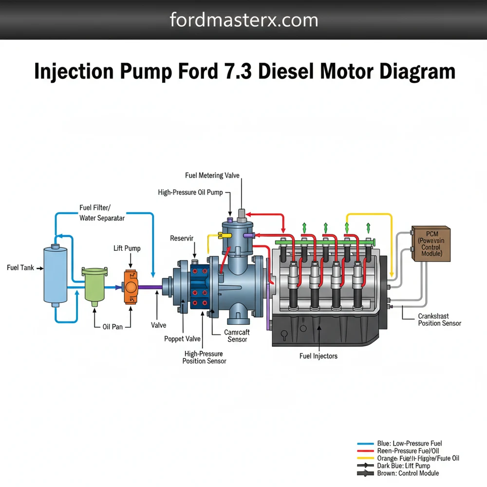
The injection pump ford 7.3 diesel motor diagram illustrates the high-pressure fuel system layout, typically centered at the front of the engine valley. It details how fuel moves from supply lines through the pump assembly to injectors, highlighting the precise configuration needed for combustion timing and pressure management within the motor’s structure.
📌 Key Takeaways
- Visualizing the high-pressure fuel system configuration for easier maintenance.
- Identifying the injection pump and its related high-pressure delivery lines.
- Bleeding the system is a critical safety step after any component replacement.
- Check for leaks at the specific fittings highlighted in the diagram layout.
- Use this diagram when diagnosing no-start conditions or rough idle issues.
When you are working on a classic heavy-duty truck, having a clear and accurate injection pump ford 7.3 diesel motor diagram is the difference between a successful weekend project and a frustrating mechanical setback. Whether you are dealing with a hard-start condition, a fuel leak, or a complete pump failure, understanding the specific blueprint of your fuel delivery system is essential. This guide is designed to provide you with a comprehensive overview of the fuel injection pump used in the 7.3L Indirect Injection (IDI) engine, which was the backbone of Ford’s diesel lineup for years. By the end of this article, you will understand how to identify every critical component, how the system configuration facilitates combustion, and how to use technical schematics to troubleshoot your motor effectively.
It is important to distinguish between the 7.3L IDI (1988–1994) and the 7.3L Powerstroke (1994.5–2003). The IDI uses a mechanical rotary injection pump (Stanadyne DB2), while the Powerstroke uses a High-Pressure Oil Pump (HPOP) and HEUI injectors. This diagram specifically covers the mechanical injection pump system found on the IDI platform.
Deep Dive into the 7.3 Diesel Injection Pump Layout
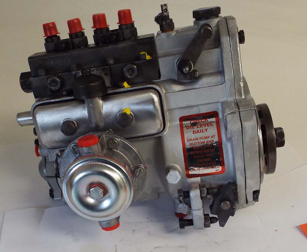
The injection pump on a 7.3 diesel motor is a marvel of mechanical engineering. Specifically, the Stanadyne DB2 pump serves as the heart of the engine’s fuel system. When viewing a detailed schematic of this component, the first thing you will notice is its rotary design. Unlike “inline” pumps found on larger commercial engines, the rotary pump uses a single distributing rotor to send high-pressure fuel to all eight cylinders in a specific firing order.
The structure of the pump is divided into several key sections. At the front of the pump is the drive shaft, which connects to the engine’s timing gear. This ensures that the fuel injection is perfectly synchronized with the piston movement. Moving toward the center, you will find the governor assembly. This mechanical system uses spinning weights and springs to manage engine RPM and prevent over-speeding. The most critical part for most DIY mechanics is the distributing head. This rear section of the pump features eight high-pressure outlets arranged in a circular layout. Each outlet is connected to a steel fuel line that travels to an individual fuel injector located in the cylinder head.
The visual representation also highlights the “top cover” of the pump. This is where the throttle linkage and the Cold Advance solenoid are located. If you are looking at a blueprint of the pump’s exterior, you will also see the fuel inlet, where the lift pump sends low-pressure fuel, and the fuel return line, which sends excess fuel back to the tank to help cool the internal components.
[DIAGRAM_PLACEHOLDER: A detailed 3D schematic showing the Ford 7.3 IDI Stanadyne DB2 Injection Pump. Labels point to: 1. Drive Shaft, 2. Timing Mark, 3. Governor Weights, 4. Metering Valve, 5. High-Pressure Outlets, 6. Fuel Shut-Off Solenoid (FSS), 7. Cold Advance Solenoid, 8. Throttle Lever.]
Color-coding in modern diagrams often helps separate the low-pressure “suction” side from the high-pressure “delivery” side. In most professional layouts, green represents the low-pressure fuel entering the pump, while red or orange represents the extremely high-pressure fuel (reaching upwards of 1,800 to 2,000 PSI) being sent to the injectors. Understanding this distinction is vital for safety, as high-pressure fuel can easily penetrate the skin.
Step-by-Step Guide: Reading and Using the Injection Pump Diagram
Interpreting an injection pump ford 7.3 diesel motor diagram requires a systematic approach. Whether you are performing a timing adjustment or replacing the entire unit, following these steps will ensure you use the schematic correctly.
- ✓ Step 1: Orient the Pump to the Timing Gear – Locate the drive shaft on your diagram. Notice the “keyway” or dowel pin. When looking at the physical motor, this must align with the drive gear inside the timing cover. Never turn the engine over while the pump is removed.
- ✓ Step 2: Identify Electrical Connections – Look for the Fuel Shut-off Solenoid (FSS) on the schematic. This is the wire that tells the engine to run or stop. If this component isn’t receiving 12 volts, your truck will never start.
- ✓ Step 3: Trace the Firing Order – Follow the high-pressure lines from the distributing head. The diagram will show which outlet corresponds to which cylinder. On a 7.3 IDI, the firing order is 1-2-7-3-4-5-6-8. Mixing these up will cause a severe misfire.
- ✓ Step 4: Locate the Timing Marks – On the flange where the pump meets the engine block, look for a small scribed line. This is your static timing mark. Aligning these marks is the “baseline” for a smooth-running motor.
- ✓ Step 5: Check the Return Path – Identify the “top hat” connector on the diagram. This is where the return lines from the injectors and the pump meet. Blockages here can cause the pump to build internal pressure and stall the engine.
- ✓ Step 6: Inspect the Metering Valve – While internal, the metering valve is shown in cross-section blueprints. This valve controls how much fuel enters the high-pressure chamber. If it sticks (usually from sitting with old fuel), the engine will not start.
When working with high-pressure fuel lines, never use your fingers to check for leaks while the engine is running. High-pressure diesel can cause “fuel injection injury,” which is a medical emergency that requires immediate surgical attention.
To perform these tasks, you will generally need a basic set of mechanics’ tools:
- • 1/2″ and 9/16″ flare nut wrenches (for fuel lines)
- • 12mm socket (for the pump mounting nuts)
- • Torque wrench capable of 15-25 ft-lbs
- • Clean lint-free rags and brake cleaner for degreasing
Troubleshooting Using Your Pump Diagram
A schematic isn’t just for installation; it is a powerful diagnostic tool. If your 7.3 diesel motor is experiencing issues, the injection pump is often the first place to look. One of the most common problems is “heat soak.” This occurs when the internal tolerances of the distributing head become worn. When the engine is hot, the metal expands, and the pump can no longer build enough pressure to pop the injectors. If you refer to your diagram, the distributing head is the component responsible for this failure.
Another frequent issue is air intrusion. By looking at the layout of the fuel inlet and the injector return lines, you can see how air might enter the system. If a return line cap is cracked, air can bleed back into the pump while the truck is parked, causing it to lose prime. The diagram helps you trace the path of the fuel to find exactly where a seal might have failed.
If your truck won’t start when hot, try pouring a gallon of room-temperature water over the injection pump head. If the truck starts immediately after, the internal head and rotor are worn out, and the pump needs to be replaced.
Warning signs of a failing pump include:
- • Excessive gray or white smoke at idle.
- • A “hunting” idle where the RPMs fluctuate.
- • Significant loss of power under load.
- • Fuel leaking from the weep hole on the underside of the pump.
Best Practices and Maintenance for the 7.3 Injection System
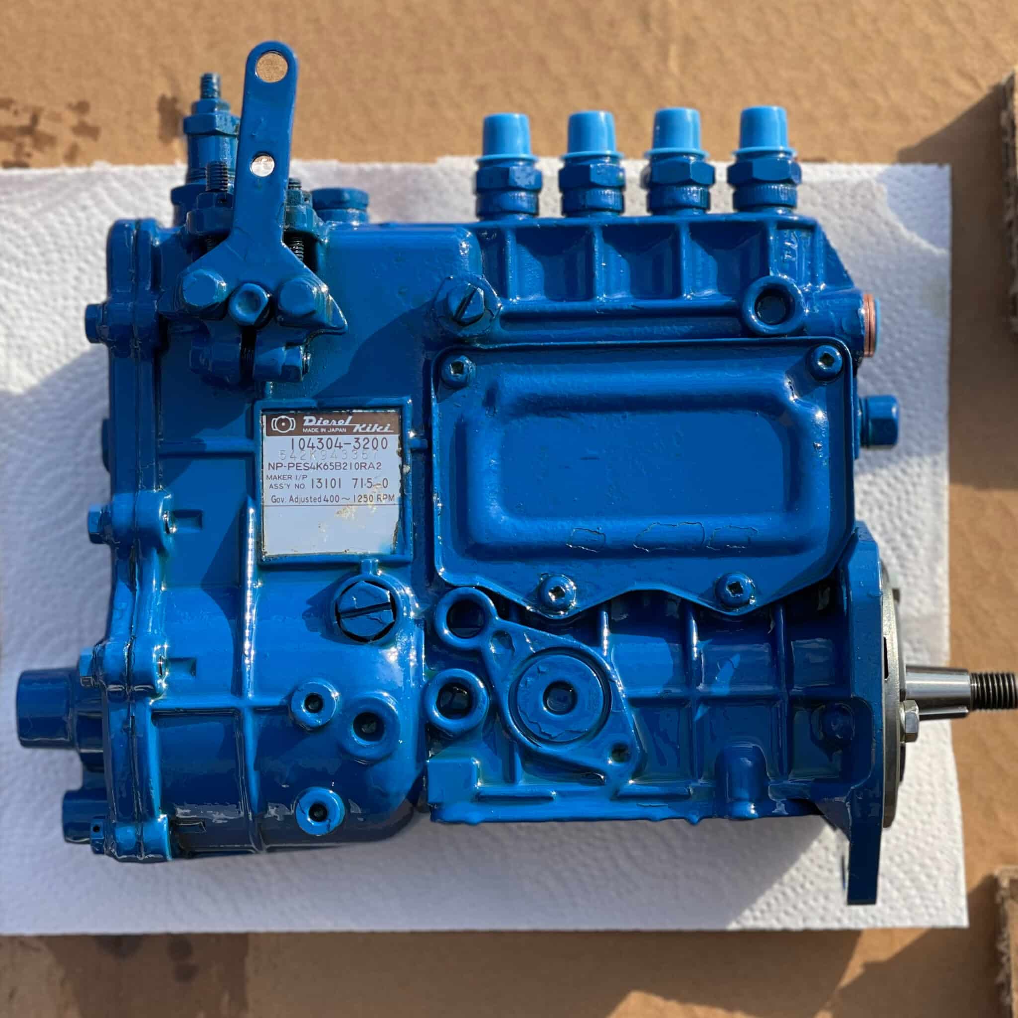
To keep your 7.3 diesel motor running smoothly, maintaining the injection pump is non-negotiable. The Stanadyne DB2 was designed in an era of high-sulfur diesel. Today’s Ultra-Low Sulfur Diesel (ULSD) is “dryer” and provides less lubrication for the internal rotating components. This makes fuel additives highly recommended for modern owners.
Maintaining the structure of your fuel system also involves regular filter changes. A clogged fuel filter forces the internal transfer pump to work harder, which can lead to premature failure of the drive shaft seals. Always use high-quality, name-brand filters that meet or exceed OEM specifications.
Change your fuel filter every 10,000 to 15,000 miles. When you install a new filter, fill it with a clean diesel fuel additive or clean diesel fuel to avoid introducing a massive air pocket into the injection pump.
When it comes to cost-saving, many owners consider rebuilding the pump themselves. While diagrams of the internal configuration are available, this is generally not recommended for beginners. The DB2 pump requires specialized calibration equipment to ensure each cylinder receives the exact same amount of fuel at the exact same time. A pump that is out of balance can cause engine vibration and even internal piston damage over time. It is usually more cost-effective to purchase a quality remanufactured unit from a reputable diesel shop that provides a bench-test report.
In conclusion, having an injection pump ford 7.3 diesel motor diagram is your first step toward mastering this legendary engine. By understanding the mechanical layout, identifying the high-pressure system components, and following a logical troubleshooting path, you can ensure your Ford truck stays on the road for hundreds of thousands of miles. Remember that cleanliness is the most important factor when working on diesel fuel systems—even a microscopic speck of dirt can ruin an injection pump’s distributing head. Respect the blueprint, follow the safety precautions, and your 7.3 motor will reward you with unparalleled reliability.
Frequently Asked Questions
Where is the injection pump located?
On the Ford 7.3 IDI diesel motor, the injection pump is centrally located at the front of the engine valley, driven by the timing gears. On the Powerstroke version, the high-pressure oil pump (HPOP) occupies this area to actuate injectors, but both require precise alignment within the engine structure.
What does this diagram show?
The injection pump ford 7.3 diesel motor diagram illustrates the comprehensive fuel delivery layout. It highlights the relationship between the pump, high-pressure lines, and injectors. This visual guide helps users understand the system configuration, identifying where fuel enters the pump and how it is distributed to each cylinder.
How many connections does the injection pump have?
The injection pump typically features eight high-pressure output connections leading to the injectors, along with an inlet fuel supply line and a return line. The internal structure also includes electrical connectors for the fuel shut-off solenoid and cold start advance, vital for modern system operation and control.
What are the symptoms of a bad injection pump?
Common signs of a failing injection pump include hard starting when the engine is warm, excessive smoke, engine hesitation, or a complete no-start condition. If the internal component fails, it cannot maintain the pressure required by the system configuration, leading to poor combustion and significant power loss.
Can I replace this myself?
Yes, replacing the pump is possible for an experienced DIYer, but it requires careful attention to timing and clean workspace practices. Following the layout in a detailed diagram is essential to ensure every line is reconnected correctly and the pump is properly indexed to the drive gear.
What tools do I need for this task?
You will need a standard socket set, torque wrench, and specialized flare nut wrenches for the fuel lines to prevent stripping. A gear housing puller might be necessary depending on your specific engine configuration to safely access the pump without damaging the surrounding timing components or structure.


