Ford Supplemental Restraint System (SRS) Diagnostics, Repair, and Reset Procedures
In the hierarchy of automotive warning indicators, the Supplemental Restraint System (SRS) light—colloquially known as the airbag light—occupies a tier of immediate criticality that supersedes almost all other passive alerts. Unlike the Check Engine Light, which often denotes an emissions variance that allows for continued vehicle operation, the illumination of the SRS indicator represents a binary suspension of the vehicle’s safety protocols.
When this light is active, the system has detected a fault within the restraint architecture that compromises its integrity. The default logic of the Restraint Control Module (RCM) in such scenarios is almost invariably to disable the deployment capability to prevent accidental misfires.
For Ford owners, technicians, and fleet managers, the challenge of the airbag light lies in its ambiguity. It is a singular indicator masking a complex network of pyrotechnic actuators, piezoelectric sensors, and digital logic gates. The widely circulated consumer myth that a simple “reset button” exists, or that disconnecting the battery will permanently resolve the issue, frequently leads to misdiagnosis and dangerous repair attempts.
A true resolution requires a nuanced understanding of the difference between transient electrical anomalies (“soft codes”) and permanent hardware failures (“hard codes”) or non-volatile memory locks (“crash data”).
This report provides an exhaustive technical breakdown of the Ford SRS architecture, diagnostic methodologies (including legacy Light Flash Codes and modern CAN bus interrogation), and validated repair procedures ranging from connector maintenance to EEPROM module reprogramming. It is designed to serve as a definitive resource for understanding why the light illuminates and the precise, engineering-grade steps required to reset it safely and permanently.
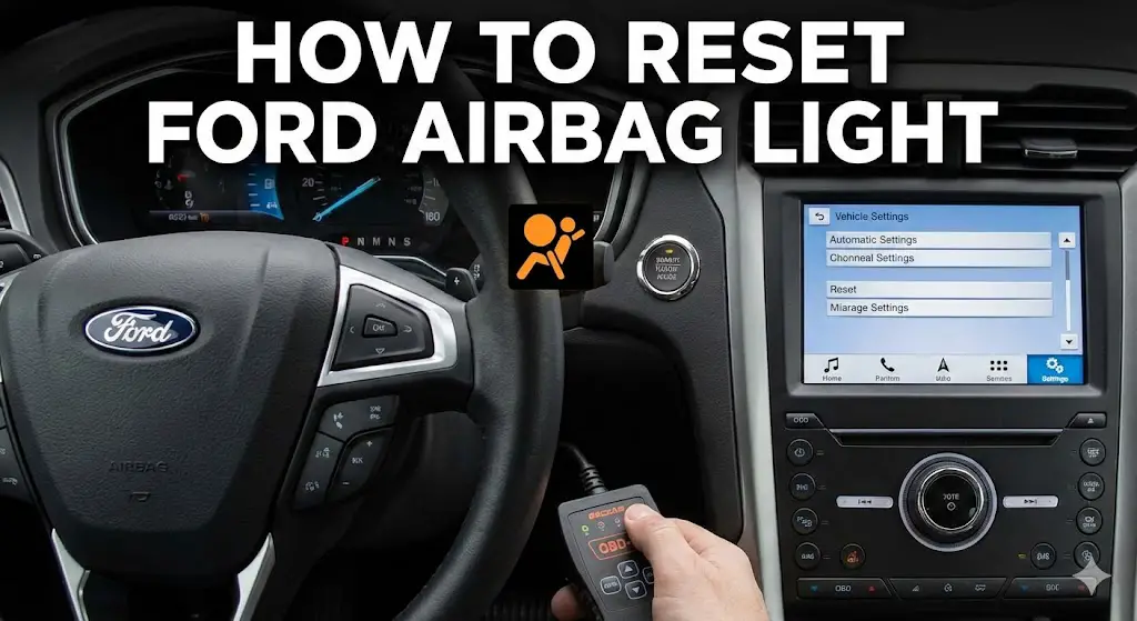
How to Reset Ford Airbag Light
Diagnosis, Manual Reset Methods, and Repair Data
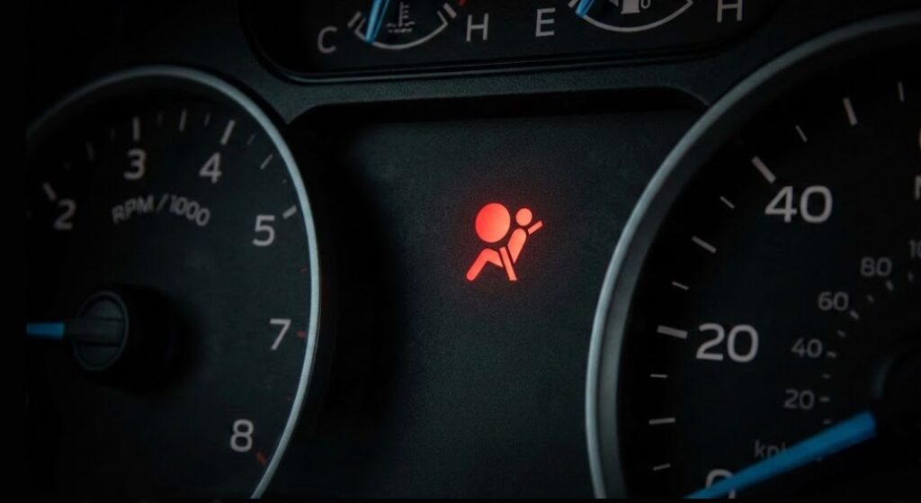
⚠️ Safety First: Understanding the Light
The Supplemental Restraint System (SRS) light indicates a fault in the airbag system. When this light is on, airbags will NOT deploy in an accident. While a “reset” can clear glitch codes, hard faults (broken parts) must be repaired first.
OBD2 Required for Most
Deployment if Light is On
Fixes Possible
Method 1: The “Key Cycle” Trick
For many Ford models (Focus, Fusion, F-150 approx 2000-2011), a “soft code” can be cleared without a scanner using this specific ignition sequence.
Ignition ON
Turn key to “Run” (engine off). Watch the airbag light.
Wait 7 Seconds
The light will stay lit for ~7 seconds. Wait until it just turns off.
Ignition OFF
Immediately turn the key off and wait 3 seconds.
Repeat x3
Repeat the whole cycle 3 times. Then start the engine.
Why is the light on?
Most airbag faults are not actually broken airbags. They are often loose connections. This chart shows the frequency of common Ford SRS issues based on mechanic forum data.
Cost Analysis: DIY vs. Mechanic
Fixing an airbag light can be cheap if it’s just a loose plug, or expensive if it’s a module. Here is a breakdown of average repair costs for common Ford issues. The “Clock Spring” is a frequent failure point in F-150s and Mustangs.
Diagnostic Workflow
Before buying parts, follow this logical path. Always disconnect the negative battery terminal and wait 15 minutes before touching yellow SRS plugs.
1. Check Under Seats
Yellow connectors under front seats often get kicked loose. Unplug/replug.
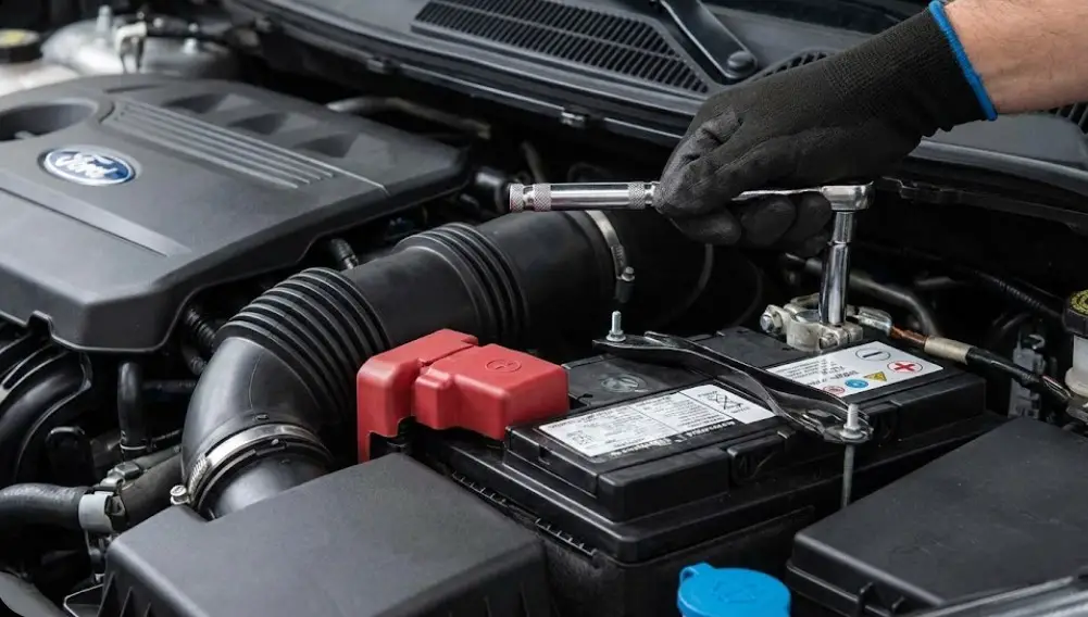
2. Check Battery
Low voltage causes system errors. Ensure battery is >12.4V.
3. Scan Codes
Use an SRS-capable OBD2 scanner. Standard engine scanners won’t work.
4. Inspect Sensors
Check front crash sensors near the radiator for corrosion or wire damage.
Quick Reference: Common Ford SRS Codes
| Flash Code (Older) | OBD2 Code | Likely Issue |
|---|---|---|
| 1-8 or 1-9 | B1000 | Driver Airbag (Often Clock Spring) |
| 3-3 | B2293 | Pretensioner Fault (Check Seat Belt) |
| 4-1 or 4-2 | B1231 | Crash Sensor Connection (Front) |
*Note: Flash codes (light blinks) are found on older models (pre-2008). Newer models require a scanner to read the “B” body codes.
© 2026 FordMasterX Infographics. Data sourced from manufacturer owner manuals.
Ford SRS Architecture and Safety Protocols
To diagnose an SRS fault effectively, one must first understand the signal flow and the fail-safe mechanisms inherent in the system’s design. The Ford SRS is not a single component but a distributed network of sensors and actuators managed by a central processor.
The Restraint Control Module (RCM)
The RCM is the “brain” of the system. Typically bolted to the transmission tunnel or floor pan to be as close to the vehicle’s center of gravity as possible, the RCM contains internal accelerometers and the decision-making logic for deployment. It continuously monitors inputs from peripheral sensors. If the RCM detects a deceleration profile that matches a pre-programmed crash algorithm, it sends a high-current pulse to the appropriate igniters. Crucially, the RCM performs a Power-On Self-Test (POST) every time the ignition is cycled. It checks the resistance of every circuit—airbags, pretensioners, and sensors. If any circuit returns a resistance value outside the expected range (typically 2.0 to 3.0 ohms for squib circuits), the RCM logs a fault and illuminates the warning light.
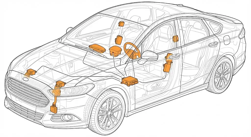
Distributed Sensor Network
The RCM relies on a constellation of external sensors to confirm crash events:
- Front Impact Sensors: Located on the radiator support or front frame rails, these sensors (often accelerometers or ball-in-tube electromechanical switches) provide the primary signal for frontal collisions.
- Side Impact Sensors: Located in the B-pillars or inside the door cavities, these detect lateral intrusion forces.
- Occupant Classification System (OCS): A sophisticated subsystem found in the passenger seat of modern Fords (Focus, Fusion, F-150). It utilizes a silicone gel bladder pressure sensor or rail-mounted strain gauges to determine the weight of the passenger. This data dictates whether the passenger airbag should deploy at full force, suppressed force, or not at all (to protect children or car seats).
- Seat Belt Switches: Hall-effect sensors or mechanical switches in the buckles that tell the RCM if occupants are belted, which influences the deployment strategy and pretensioner activation.
The Capacitor Discharge Safety Protocol
A critical design feature of the RCM is its energy reserve. In a severe collision, the battery cables are often severed early in the impact sequence. To ensure the airbags can still fire, the RCM contains large capacitors capable of storing enough electrical energy to detonate the squibs.
Critical Safety Protocol: Before servicing any SRS component—whether unplugging a seat connector or replacing a clock spring—the vehicle’s 12V battery must be disconnected to isolate the power source. While some engineering sources suggest the capacitors discharge in as little as one minute, field safety protocols and manufacturer guidelines strongly advocate for a minimum wait time of 15 to 30 minutes. This duration ensures that all residual voltage in the RCM capacitors has dissipated below the threshold required to trigger the pyrotechnic initiators. Failure to observe this wait time can result in accidental deployment, causing severe injury from the expanding bag or the high-velocity plastic trim fragments.
The Deployment Mechanism: Squibs and Pretensioners
The actual deployment is achieved via “squibs”—small explosive devices within the airbag inflator and seat belt pretensioner.
- Airbags: When the squib fires, it ignites a solid propellant (like sodium azide or guanidine nitrate), generating a massive volume of nitrogen gas that inflates the nylon bag in milliseconds.
- Pretensioners: Often overlooked, the seat belt pretensioners are also pyrotechnic. Upon impact, they fire a charge that drives a piston or rotates a spool to retract the seat belt webbing, pulling the occupant firmly into the seat just before the airbag strikes. A common diagnostic oversight is checking the airbags but failing to check the pretensioners, which may have deployed (and thus ruined) during a minor impact that didn’t trigger the main bags.
Diagnostic Methodologies: Decoding the Fault
Ford utilizes a dual-layer diagnostic system. The interpretation of these signals is the primary filter between a quick repair and an expensive dealership visit. The system broadcasts faults via Light Flash Codes (LFC) on the instrument cluster and digital Body Codes (B-codes) via the OBDII port.
Tier 1 Diagnostics: Light Flash Codes (LFC)
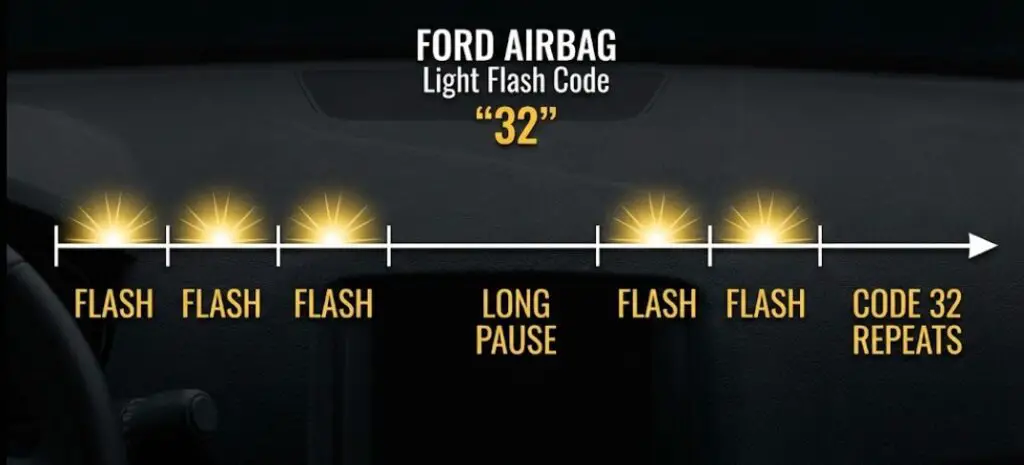
When the RCM detects a fault, it attempts to communicate the general location of the issue to the driver or technician without the need for a scanner. This is the Light Flash Code (LFC) system. The airbag light will flash a two-digit number: a series of flashes for the first digit, a pause, and a series of flashes for the second digit. This cycle repeats several times before the light stays solid.
Interpreting these codes is the first step in “triage.” The following table consolidates data from multiple service manuals and technician reports to provide a comprehensive LFC lookup for Ford vehicles (approx. model years 2004–2019).
Table 1: Comprehensive Ford Airbag Light Flash Codes (LFC)
| LFC | Component / System | Technical Description | Likely Root Cause & Context |
| 12 | Power Supply | Lost Battery Feed | Blown fuse supplying the RCM; severed main harness. |
| 13 | Airbag Circuit | Circuit Short to Ground | Pinched wire touching the chassis; usually in the steering column or seat rails. |
| 19 | RCM / Memory | Crash Data Memory Full | The vehicle has been involved in a collision. The RCM has locked its EEPROM. Requires replacement or professional reset. |
| 21 | RCM Mounting | RCM Ground Resistance High | Corrosion between the RCM metal housing and the vehicle chassis. Loose mounting bolts. |
| 32 | Driver Airbag | Circuit High Resistance / Open | Clock Spring Failure. The ribbon cable has fractured. This is the single most common code for high-mileage Fords. |
| 33 | Pass. Airbag | Circuit High Resistance / Open | Yellow Connector Fault. The connector under the passenger seat has loose pins or fretting corrosion. |
| 34 | Driver Airbag | Circuit Low Resistance / Short | Shorted clock spring internal windings or wires pinched behind the steering wheel airbag module. |
| 41 | Front Right Sensor | Sensor Feed/Return Open | Impact damage to the wire harness near the radiator support; sensor unplugged or corroded. |
| 42 | Front Left Sensor | Sensor Feed/Return Open | Similar to Code 41 but on the driver’s side front impact sensor. |
| 46 | Driver Belt | Pretensioner Circuit Fault | High resistance in the under-seat connector (driver side); failed pretensioner squib. |
| 47 | Pass. Belt | Pretensioner Circuit Fault | High resistance in the under-seat connector (passenger side); failed pretensioner squib. |
| 51 | RCM Internal | Thermal Fuse Blown | Internal RCM failure, often caused by a short circuit in the system diverting high voltage to the module. |
| 52 | Power Supply | Backup Power Supply Fault | Failure of the internal capacitors within the RCM to hold charge. |
| 53 | Crash Sensor | Signal Failure / internal Fault | RCM cannot verify the integrity of the front crash sensors. |
Detailed Analysis of Common LFCs:
- Code 19 (Crash Data): This is definitive. It means the system did its job during an event. The light will not turn off until the module is serviced.
- Code 32 vs. 33: These are the “wear and tear” codes. Code 32 almost invariably points to the clock spring because it is a moving part subject to millions of rotation cycles. Code 33 points to the static connectors under the seat, which are only disturbed when the seat is adjusted, yet they are notorious for high sensitivity to resistance changes.
Tier 2 Diagnostics: OBDII and DTCs (Digital Trouble Codes)
While LFCs provide a “zone” for the fault, modern repair requires the precision of OBDII Digital Trouble Codes (DTCs). These are retrieved using the Data Link Connector (DLC) usually found under the steering column.
The Scanner Trap: A critical distinction must be made regarding scan tools. Standard “Code Readers” sold for $20-$50 at auto parts stores typically only read the PCM (Powertrain Control Module) for engine faults (P-codes). They generally cannot access the RCM (Restraint Control Module) or the BCM (Body Control Module). To read airbag codes, a scanner must support the specific MS-CAN (Medium Speed Controller Area Network) or HS-CAN (High Speed) protocols used by Ford safety systems, and have the software keys to interpret “B-codes” (Body codes).
Common Ford SRS OBDII Codes:
- B0001: Driver Frontal Stage 1 Deployment Control.
- B0002: Driver Frontal Stage 2 Deployment Control (for dual-stage airbags).
- B1193: Crash Data Memory Full / Locked. This is the digital equivalent of LFC 19.
- U3000: Control Module Internal Failure. The “U” prefix indicates a communication network fault, but in the context of the RCM, U3000 often accompanies internal hardware damage or corrupted memory.
- B1877: Driver Knee Airbag Circuit Failure.
- B1881: Crash Sensor Communication Fault.
- B141B: Rear Inflatable Seatbelt Deployment Control (Specific to F-150/Explorer).
The Importance of Sub-Codes:
Advanced scanners (like Forscan or Autel) will provide a sub-code (e.g., B0001:13).
- :11 = Short to Ground.
- :12 = Short to Battery.
- :13 = Circuit Open (Broken wire).
- :1A = Circuit Resistance Below Threshold.
- :1B = Circuit Resistance Above Threshold.This granularity allows the technician to know if they are looking for a cut wire (:13) or a corroded connector pin (:1B).
Common Failure Points and Resolution Protocols
The analysis of thousands of Ford service cases reveals three dominant failure modes that account for the vast majority of non-collision airbag lights. Understanding the physics and mechanics of these failures is essential for a permanent fix.
The “Yellow Connector” Issue (Focus, Fusion, Fiesta, Mustang)
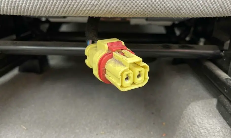
One of the most widespread causes of intermittent airbag lights in Ford vehicles—specifically triggering LFC 33/47 (Passenger) or LFC 32/46 (Driver)—is the yellow electrical connector located beneath the front seats.
- System Context: This connector serves as the umbilical cord between the main body wiring harness and the seat-mounted safety components, which include the side-impact airbag (in the seat bolster) and the seat belt pretensioner buckle.
- Mechanism of Failure: The environment under a car seat is hostile. It is subject to vibration, occasional moisture, and physical movement. When the seat is adjusted forward or backward, the harness flexes. Over time, this mechanical stress, combined with microscopic thermal expansion and contraction, causes fretting corrosion on the tin or gold-plated terminals inside the yellow connector.
- Resistance Thresholds: The RCM monitors this circuit continuously. It expects a resistance of approximately 2.0 to 3.0 ohms. Even a slight oxidation layer or loose pin tension can spike the resistance to 4.0 ohms or higher for a fraction of a second. The RCM latches this as a fault.
- Diagnostic Verification: A simple field test involves turning the ignition on (engine off) and wiggling the yellow connector or sliding the seat back and forth. If the light creates a new code or if the status changes (on Forscan live data), the connector is the culprit.
- Repair Protocol:
- Disconnect Battery: Wait 20 minutes.
- Inspect: Unplug the yellow connector. Look for “pin spread” (where the female terminal has opened up and doesn’t grip the male pin tightly).
- Clean and Grease: Use electrical contact cleaner. Apply a specific dielectric grease (Ford Specification XG-12 is often recommended) to prevent future oxidation.
- CPA Tabs: Ensure the Connector Position Assurance (CPA) tab—usually a red or white locking slide—is fully engaged. This tab often pushes down “shorting bars” that automatically short the airbag circuit when unplugged to prevent static discharge firing. If the CPA tab isn’t seated, the shorting bars may remain active, causing a “Short circuit” code.
- The “Hardwire” Fix: For persistent cases out of warranty, many technicians cut the connector out entirely and solder the wires together (shrink-wrapping them). This eliminates the fretting point permanently but makes removing the seat in the future difficult
The Clock Spring (F-150, Explorer, Expedition)
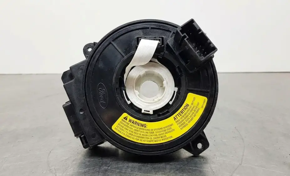
The clock spring (technically the Sliding Contact Assembly) is a rotary electrical connector located behind the steering wheel. It enables the wheel to turn lock-to-lock while maintaining electrical continuity to the driver’s airbag, horn, and cruise control buttons.
- Symptoms: Airbag Code 32 (High Resistance/Open Circuit Driver Airbag). This is often accompanied by the loss of horn function or cruise control buttons, as they share the same ribbon cable. A distinct “crunching” or “clicking” sound from the steering column when turning is a physical indicator of ribbon failure.
- Technical Failure Mode: The internal component is a flat ribbon cable wound in a spiral. Over years of steering, the ribbon fatigues and eventually fractures, creating an open circuit (Infinite resistance).
- Replacement Economics: The clock spring is not repairable; it must be replaced.
- Part Cost: OEM Motorcraft parts range from $150 to $350 depending on trim level (heated steering wheels require more complex clock springs). Aftermarket units are cheaper ($50-$100) but have higher failure rates.
- Labor: Replacement requires removing the airbag module and steering wheel. A shop typically charges 1.0 to 1.5 hours of labor, bringing the total to $450-$600.
F-150 Rear Inflatable Seatbelts
Certain high-trim F-150s (Platinum, King Ranch) and Explorers are equipped with inflatable rear seatbelts—essentially mini-airbags integrated into the shoulder belt. These introduce a complex failure mode involving the belt buckle interface.
- Fault: The interface between the belt tab and the buckle contains gold-plated data pins. These wear out or get dirty, triggering a “Rear Belt Monitor Fault” message on the dash or an airbag light.
- Codes: Often generates B141B (Driver side rear) or similar B-codes, or LFC 47.
- Resolution: Cleaning sometimes works, but often the seatbelt buckle assembly (the female end attached to the seat) requires replacement. The part cost is approximately $236.
The “Reset” Myth vs. Reality: Clearing Codes vs. Clearing Crash Data
A fundamental misunderstanding exists among vehicle owners regarding “resetting” the airbag light. There is no universal reset. The action required depends entirely on the type of data stored in the RCM. There are three distinct categories of “reset,” each requiring different procedures.
The Soft Reset (Ignition Cycle / Battery)
- Scope: Transient glitches, low battery voltage errors, soft logic freezes.
- Procedure:
- Turn ignition ON (engine off).
- Watch the airbag light. It will stay solid for about 6-7 seconds.
- The moment the light turns off (before it starts flashing or comes back on), turn the ignition OFF.
- Wait 3 seconds.
- Repeat steps 1-4 for a total of three cycles.
- Turn ignition ON and start the engine.
- Mechanism: This procedure forces the RCM to re-initialize its diagnostic stack. It is effective only if the fault was a one-time logic error or a low-voltage event during cranking.
- Battery Disconnect: Disconnecting the negative terminal for 15+ minutes drains the Volatile Memory (RAM) of the module. This can clear “pending” codes, but it will not clear confirmed hard codes stored in Non-Volatile Memory (EEPROM).
- Reality Check: If a hard fault (e.g., a broken clock spring wire) exists, the RCM will run its POST, detect the open circuit, and re-illuminate the light immediately. You cannot “reset” a broken wire.
The Diagnostic Reset (Scanner Clearing)
- Scope: “Soft codes” stored in history after a physical repair is made.
- Scenario: You had a loose plug (Code 33), you reconnected/repaired it. The light might stay on because the code is stored as “History” or “Pending.”
- Procedure: Use a high-level scanner (Forscan, Snap-On, Autel) to send a “Clear DTCs” command to the RCM module.
- Outcome: If the physical repair was successful, the light stays off. If the repair failed, the code returns instantly.
The Hard Memory Reset (Crash Data Scrubbing)
- Scope: Vehicles involved in a collision where airbags deployed or seatbelt pretensioners locked.
- The Problem: When an accident occurs, the RCM writes “Crash Data” (often called “Hard Codes”) to a specific sector of its EEPROM (Electrically Erasable Programmable Read-Only Memory). This triggers Code 19 or B1193. This data is “locked” and cannot be cleared by standard scanners, nor by dealer diagnostic tools (IDS/FDRS).15 The manufacturer’s official repair is to replace the entire RCM hardware, which can cost $400-$1200 depending on the model.
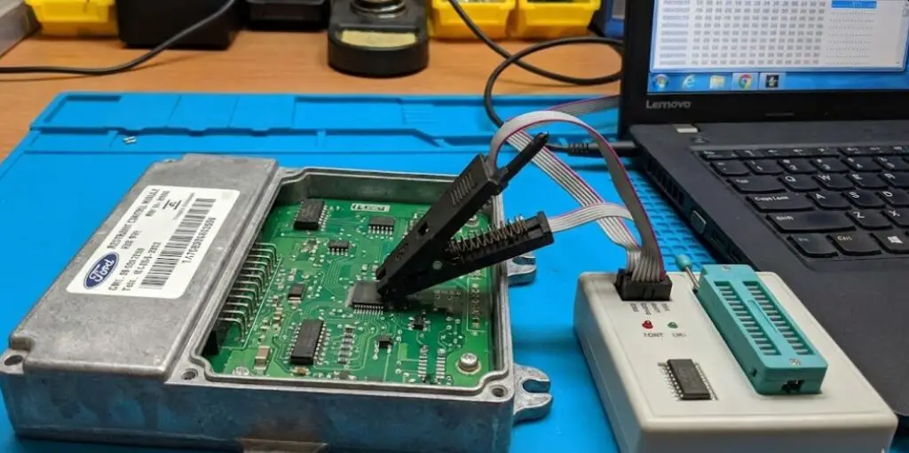
- The Solution (Reset Service): A specialized industry has emerged to address this. “Module Reset Services” (e.g., SafetyRestore, MyAirbags, Module Repair Lab) use bench-top EEPROM programmers.
- Process: The RCM is removed from the car and mailed to the service. The technician opens the casing, clamps onto the EEPROM chip (or connects via the pinout), and downloads the binary file (“bin file”).
- Scrubbing: Specialized software compares the bin file against a “clean” factory file, identifies the crash event strings (hexadecimal data), and overwrites them with “00” or the factory default values, effectively wiping the memory of the crash.
- Advantage: This retains the vehicle’s specific VIN and configuration data (As-Built data), making the module “Plug-and-Play” upon return. It avoids the need for dealership reprogramming.
- Cost Efficiency: Resetting a module typically costs $50-$150, representing a savings of 80-90% compared to a new module installation.
Technical Guide: Resetting the Airbag Light Using Forscan
For the DIY enthusiast or independent mechanic, Forscan is arguably the most powerful tool available for diagnosing and resetting Ford SRS systems. It is a software specifically engineered for Ford/Lincoln/Mazda vehicles that accesses manufacturer-specific protocols often hidden from generic tools.
Requirements
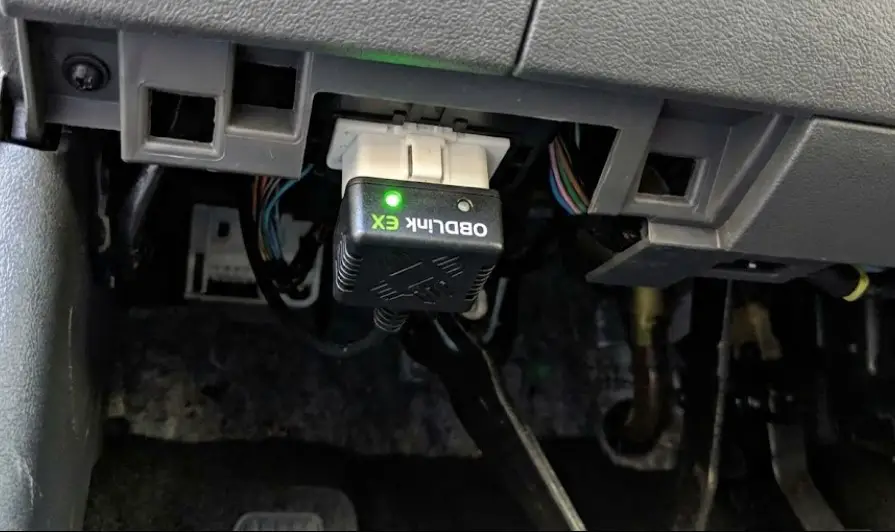
- Hardware: An OBDII to USB or Bluetooth adapter. Crucially, the adapter must support both HS-CAN and MS-CAN switching. The RCM often resides on the MS-CAN (Medium Speed) bus in older Fords or requires specific switching logic. The OBDLink EX is the recommended wired adapter as it switches automatically; cheaper ELM327 clones with a manual toggle switch can also work but are prone to connection errors.
- Software: Forscan (Windows version is recommended for full functionality, though Lite versions exist for Android/iOS).
- License: An “Extended License” is required for some configuration functions (PATS programming, Service procedures), though basic DTC reading and clearing usually works on the free version. The extended license is inexpensive or free for trial periods.
Step-by-Step Diagnostic and Reset Procedure
- Setup and Connection:
- Install Forscan on a Windows laptop.
- Plug the OBDLink EX into the vehicle’s OBDII port and the laptop USB.
- Turn the vehicle ignition to ON (Engine can be off).
- Launch Forscan and click the “Connect” icon (bottom left).
- The software will identify the vehicle, read the VIN, and map out all available modules (PCM, TCM, RCM, IPC, etc.). You should see “RCM” in the list. If not, your adapter may not be reading the correct CAN bus.
- Reading the Codes (The Diagnosis):
- Navigate to the DTC (Diagnostic Trouble Codes) tab (triangle icon).
- Forscan will list codes by module. Scroll to the RCM section.
- Read the full code description. Example:
Code: B0001:13-8B.B0001= Driver Frontal Stage 1.:13= Circuit Open.- This tells you specifically to look for a broken wire (likely clock spring) rather than a short.46
- Live Data (Optional): Go to the oscilloscope icon (Read PID Data). Select “RCM” PIDs. You can select “Driver Airbag Resistance.” Watch the value (e.g., 5.6 ohms). Wiggle the connector. If it drops to 2.2 ohms, you have found your loose connection.
- The Repair:
- Perform the physical repair based on the code (e.g., replace the clock spring, clean the under-seat connector). Forscan cannot fix the light if the wire is still broken.
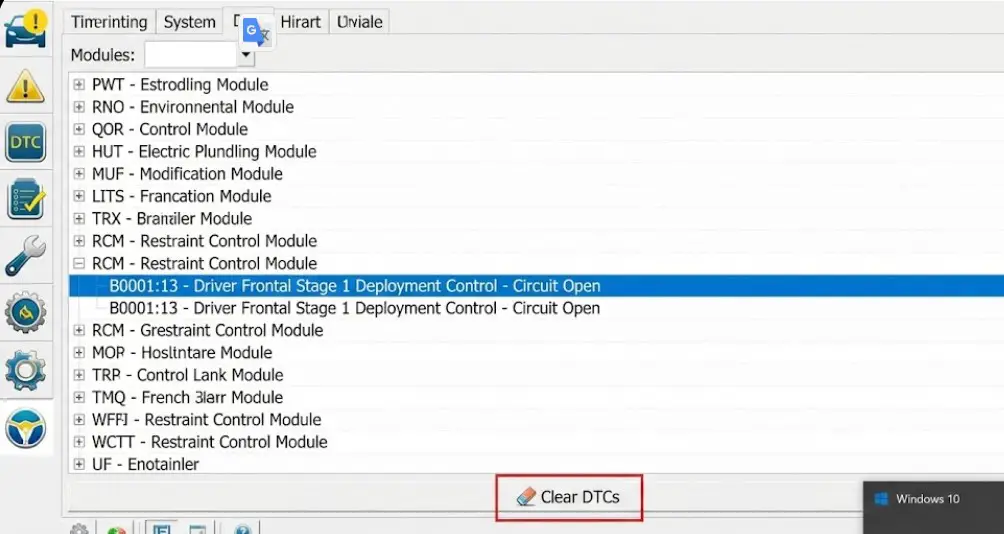
- Resetting/Clearing the Light:
- Return to the DTC tab in Forscan.
- Click the “Clear DTCs” button (often an eraser icon or “Reset DTC”).
- Confirm the prompt. Forscan will send a reset command to the RCM.
- The software will cycle the modules.
- Verification: Turn the ignition OFF, then ON. Watch the dashboard. The airbag light should illuminate for the bulb check (6 seconds) and then turn off and stay off.
Legal, Insurance, and Inspection Implications
The presence of an illuminated airbag light carries weight beyond simple mechanics; it intersects with vehicle legality and liability.
State Inspections (USA)
The legality of the airbag light varies significantly by jurisdiction in the United States.
- Texas: The airbag light is generally not an automatic fail for the annual state safety inspection. The inspection focuses on active safety systems like brakes, tires, and lights. As long as the seat belts are functional (not frayed, latch correctly), the vehicle can pass, though the inspector may note the light.
- New York: Regulations require the inspector to verify the airbag light functions (bulb check). If the light stays on, the inspector must notify the owner, but it is historically not a cause for failing the safety inspection, unlike the Check Engine Light which causes an emissions failure.
- General Rule: While it may pass inspection in some states, driving with the light on is a massive liability.
MOT Testing (UK)
In the United Kingdom, regulations are strictly defined and much more severe.
- MOT Failure: Under current DVSA rules, an illuminated SRS malfunction lamp is a Major Defect. This results in an automatic MOT failure.
- Verification: The tester checks that the light illuminates during the ignition cycle (proving the bulb works) and then extinguishes. If the light does not light up at all (indicating tampering/bulb removal) or stays on, the vehicle fails.5
Insurance Liability
Driving with a known fault (indicated by the light) exposes the driver to significant civil liability. If a passenger is injured in a collision and the airbags fail to deploy because the owner neglected the warning light, insurance companies may attempt to deny medical coverage or liability protection, citing negligence and failure to maintain safety equipment. In a lawsuit, the vehicle’s “black box” (EDR) data can prove the light was on long before the crash.
Cost Analysis: Dealer vs. DIY vs. Specialist
The financial disparity between dealership repair and informed independent repair is drastic for SRS systems. The following table illustrates the potential savings for a standard Ford F-150 or Fusion airbag repair scenario.
Table 2: Comparative SRS Repair Costs (Estimates)
| Repair Scenario | Dealership Cost (Est.) | DIY / Independent / Specialist Cost | Notes |
| Diagnostic Scan | $150 – $200 | $0 – $50 | Dealer diagnostic fees are high (1 hr labor); Forscan software is free/cheap; Auto parts stores scan for free. |
| Clock Spring Replacement | $500 – $600 | $150 – $250 | OEM Parts are ~$150 online; DIY labor is ~1 hour. Dealer marks up parts and labor. |
| Module (RCM) “Repair” | $800 – $1,200 | $50 – $150 | Biggest Savings. Dealer replaces the module with a new unit + programming fee. Specialist resets the existing module. |
| Seat Connector Repair | $300 – $500 | $10 – $20 | Dealer often replaces the entire harness ($$$). DIY fix uses zip ties, cleaning, or simple soldering. |
| Total Crash Recovery | $2,500+ | $400 – $600 | Includes belts, module reset, and sensors. |
Insight: The “Module Reset” service is the single largest cost-saver in collision recovery. By retaining the original module, the owner avoids not only the hardware cost but also the “Programmable Module Installation” (PMI) fee required to initialize a blank module to the vehicle’s VIN.
Conclusion
Resetting the airbag light on a Ford vehicle is not a singular action but a diagnostic process. The light is a symptom, a digital messenger of a physical or logical break in the safety chain. While the “Yellow Connector” under the seat and the “Clock Spring” behind the wheel account for a statistically significant majority of non-accident failures, the only safe and effective way to extinguish the light is to identify the LFC or DTC, physically rectify the electrical break, and then clear the code history using an appropriate tool like Forscan.
For vehicles involved in collisions, the emergence of EEPROM reset services has revolutionized the economics of repair, allowing RCMs to be reused safely without the prohibitive costs of dealership replacement. However, attempting to bypass these warnings through “simulators,” tape, or bulb removal is legally perilous, financially risky in terms of insurance, and physically dangerous.
Key Takeaway: If the airbag light is flashing, count the flashes. If it is Code 32 or 33, investigate the clock spring or seat plugs. If it is solid, connect a Forscan adapter to read the B-codes. But never simply “clear” the code without fixing the underlying wire—the RCM is vigilant, and it will re-illuminate the light to protect the vehicle occupants until the safety of the system is restored.