How to Clean O2 Sensor & Save $150: Ford F-150 Repair Guide 2026
The internal combustion engine operates on a fundamental principle of thermochemistry: the stoichiometric ratio. For gasoline-powered vehicles, this ideal balance—where exactly enough air is provided to completely combust the available fuel—is defined as a mass ratio of approximately 14.7:1. Maintaining this equilibrium is not merely a matter of fuel efficiency; it is a regulatory and environmental mandate enforced by global emissions standards. The primary instrument for maintaining this balance in the volatile environment of an automotive powertrain is the oxygen sensor, or lambda probe.
In the context of Ford Motor Company’s diverse powertrain portfolio—ranging from the naturally aspirated Triton V8s of the early 2000s to the complex, turbocharged EcoBoost architectures of the modern era—the oxygen sensor serves as the critical feedback mechanism for the Engine Control Unit (ECU). It provides the real-time data necessary to adjust fuel injector pulse width in milliseconds, compensating for variables such as altitude, temperature, load, and fuel quality.
However, these sensors operate in a hostile environment. Subjected to exhaust gas temperatures exceeding $800^{\circ}C$, acoustic shockwaves, and chemical contaminants, oxygen sensors are consumable components with a finite service life. As vehicles age, particularly high-utility platforms like the Ford F-150, owners frequently encounter symptoms of sensor degradation: rough idling, decreased fuel economy, and the illumination of the Malfunction Indicator Lamp (MIL).
A significant debate exists within the automotive maintenance community regarding the remediation of these sensors. While Original Equipment Manufacturers (OEMs) such as Bosch, Denso, and Motorcraft universally recommend replacement upon failure, a robust aftermarket and enthusiast sector advocates for cleaning protocols ranging from solvent baths to thermal decarbonization. This report provides an exhaustive engineering analysis of these cleaning methodologies, weighing their efficacy against the specific mechanical and economic realities of Ford vehicle ownership. It explores the physics of sensor operation, the chemistry of contamination, and the practicalities of servicing sensors in the restrictive confines of Ford engine bays.
O2 Sensor Maintenance
A Data-Driven Guide to Diagnostics, Cleaning, and Replacement
The Oxygen Sensor Dilemma
The Oxygen (O2) sensor is the nose of your vehicle’s computer (ECU). It sniffs the exhaust to determine if the fuel mixture is rich or lean. Over time, these sensors get coated in carbon soot, oil ash, or silicone glaze, leading to sluggish performance, poor fuel economy, and the dreaded Check Engine Light (Codes P0171, P0174, P0420).
The Core Question: Can you actually clean them? The short answer is YES, but only if the failure is caused by carbon fouling. Internal heater failures or silicone poisoning require replacement.
Root Cause Analysis
Understanding why your sensor failed determines if cleaning is a viable solution. Carbon buildup is the only condition reversible by cleaning.
The Economics of Cleaning
Why bother cleaning? For vehicles requiring wide-band A/F sensors or OEM Motorcraft parts, the savings are substantial compared to the cost of a can of seafoam or electronics cleaner.
The Hidden Cost: Fuel Efficiency
A “lazy” O2 sensor doesn’t always trigger a code immediately. Instead, it responds slowly to throttle changes, causing the ECU to default to a rich mixture for safety. This chart illustrates the cumulative impact on MPG over 50,000 miles of degradation.
Decision Matrix: Clean or Replace?
Follow this logic path to avoid wasting time on a dead sensor.
How to Clean Effectively
Warning: Do not use wire brushes on the sensor tip. Do not use cleaning agents containing oil or silicone.
The Soak Method (Gentle)
Submerge the sensor tip (NOT the wires) in a container of gasoline or specialized catalytic converter cleaner for 8-12 hours. Shake occasionally to dislodge soot.
Electronics Cleaner
Spray MAF or Electronics cleaner generously into the sensor holes. Allow to dry completely before installation. This removes light oily residues.
Torch Method (Extreme)
Advanced Only: Heat the tip cherry red with a propane torch to burn off hardened carbon deposits. Risk of damaging the internal heater is high.
© 2026 FordMasterX Infographics. Data sourced from manufacturer owner manuals.
Fundamentals of Exhaust Gas Sensing Technology
To evaluate the feasibility of cleaning an oxygen sensor, one must first understand the precise physical and electrochemical mechanisms by which it functions. The sensor is not a simple probe; it is a complex solid-state generator or variable resistor, depending on the specific technology employed.
The Nernst Cell: Zirconia Sensor Physics
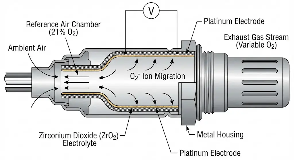
The most prevalent sensor architecture found in Ford vehicles produced between 1996 and 2010, and continued in downstream applications today, is the Zirconium Dioxide ($ZrO_2$) narrowband sensor. This device functions as a solid-state galvanic cell, operating on the Nernst principle.
The core element is a thimble-shaped ceramic body made of Zirconium Dioxide stabilized with Yttrium Oxide ($Y_2O_3$). This ceramic lattice has a unique property: at temperatures above approximately $300^{\circ}C$ ($572^{\circ}F$), it becomes conductive to oxygen ions ($O^{2-}$). The sensor construction involves coating both the inner and outer surfaces of this ceramic thimble with a microporous platinum electrode.
- The Reference Chamber: The inner surface of the ceramic is exposed to atmospheric air, which serves as a stable reference containing approximately 21% oxygen. In many Bosch designs, this reference air is drawn down through the wire harness itself, necessitating careful handling of the cabling to prevent blocking the "breathing" path.
- The Measurement Chamber: The outer surface is exposed to the exhaust gas stream.
- Ion Migration: When there is a differential in oxygen partial pressure between the exhaust gas and the reference air, oxygen ions migrate through the ceramic lattice from the side of high concentration (atmosphere) to the low concentration (exhaust).
This migration generates an electromotive force (EMF), or voltage. The magnitude of this voltage is inversely proportional to the oxygen content in the exhaust:
- Rich Mixture ($\lambda < 1$): Low exhaust oxygen concentration creates a large differential against the reference air. This drives high ion migration, generating a voltage signal between 0.8V and 0.9V.
- Lean Mixture ($\lambda > 1$): High exhaust oxygen concentration reduces the differential. Ion migration slows, dropping the voltage to 0.1V to 0.2V.
- Stoichiometry ($\lambda = 1$): The sensor output switches rapidly across the 0.45V threshold.
Implications for Cleaning: The critical vulnerability in this design is the microporous platinum electrode on the exhaust side. For the sensor to function, exhaust gas molecules must physically contact the ceramic interface. If this surface becomes coated in carbon soot, oil ash, or silicone glaze, the gas cannot reach the electrolyte. The sensor becomes "blind" or sluggish, failing to generate voltage changes rapidly enough for the ECU to maintain closed-loop control. Cleaning protocols aim to remove this physical barrier without damaging the delicate platinum coating or the ceramic substrate.
Resistive Technology: Titania Sensors
While less common in the modern Ford lineup compared to Zirconia, Titania ($TiO_2$) sensors represent a distinct technological approach that appears in select legacy applications. Unlike Zirconia sensors which generate voltage, Titania sensors act as oxygen-dependent variable resistors.
Titanium Dioxide is a semiconductor whose electrical resistance changes in response to the oxygen partial pressure in the surrounding gas.
- Rich Condition: The lack of oxygen causes the crystal lattice to lose oxygen atoms to the atmosphere, increasing the number of charge carriers (vacancies) and drastically lowering electrical resistance (often below $1,000 \Omega$).
- Lean Condition: Excess oxygen is absorbed into the lattice, reducing charge carriers and increasing resistance (often above $20,000 \Omega$).
The ECU supplies a reference voltage (typically 1V or 5V) to the sensor and measures the voltage drop across the variable resistance.
Implications for Cleaning: Titania sensors do not require a reference air chamber, making them immune to external contamination that might block the air path in a Zirconia sensor (e.g., oil or water in the connector). However, the sensing element is essentially a thick-film printed circuit on a ceramic substrate. Aggressive physical cleaning (wire brushing) or thermal shock can easily fracture this film or alter its resistive properties permanently. The absence of a reference air requirement makes them mechanically robust, but they remain chemically sensitive.
Wideband Air-Fuel Ratio (A/F) Sensors
With the advent of the EcoBoost engine family and stricter emissions tiers (Tier 2 Bin 5 / Euro 6), Ford transitioned to Wideband Air-Fuel (A/F) sensors for the upstream position. Unlike narrowband sensors that effectively act as binary switches (Rich/Lean), wideband sensors provide a linear output indicating the exact air-fuel ratio (e.g., 14.7:1, 12.5:1, 18.0:1).
The architecture of a wideband sensor is significantly more complex, consisting of two cells: a Nernst sensing cell and an oxygen pump cell, separated by a diffusion gap.
- The Nernst cell measures the oxygen potential in the diffusion gap.
- The ECU drives current into the pump cell to pump oxygen ions in or out of the gap to maintain a stoichiometric balance (0.45V) within that tiny chamber.
- The magnitude and direction of the current required to maintain this balance is the signal sent to the ECU.
Cleaning Contraindications: Wideband sensors are highly intricate. The diffusion barrier is a precisely engineered restriction that controls gas flow into the detection chamber. Cleaning agents that leave residue, or physical cleaning methods that alter the porosity of the protection tube or diffusion barrier, will destroy the sensor's calibration. Because the "signal" is a precise current measurement (milliamps) rather than a simple voltage toggle, even minor surface alterations can lead to significant fuel trim errors. Cleaning wideband sensors is broadly discouraged in engineering literature due to this sensitivity.
Sensor Heating Elements
Modern oxygen sensors are universally "heated" sensors (HO2S). Zirconia and Titania elements function effectively only above $300^{\circ}C$ to $350^{\circ}C$. To reach this temperature quickly—reducing "open loop" time and cold-start emissions—an internal ceramic resistance heater is embedded within the sensor body.
Diagnostic Relevance: A significant percentage of O2 sensor failures are actually heater failures (DTC P0135, P0141, P0155, P0161). If the internal heating wire is broken (open circuit), the sensor cannot maintain operating temperature at idle. No amount of cleaning can repair a broken electrical wire inside a ceramic block. This distinction is vital: cleaning is only a potential remedy for sensing issues (contamination), never for electrical issues (heater failure).
Pathology of Sensor Degradation: Why Sensors Fail
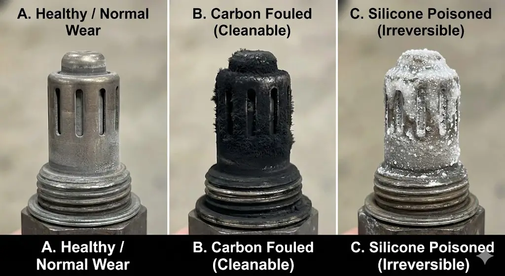
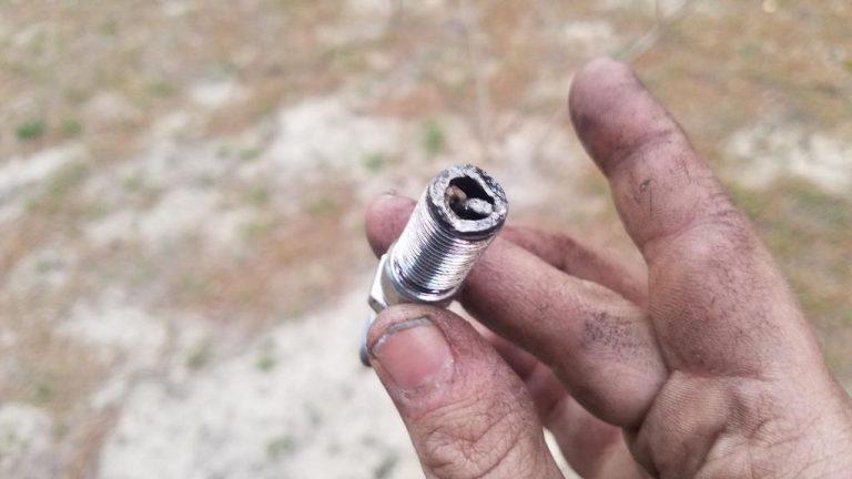
To implement an effective cleaning or replacement strategy, the vehicle operator must correctly identify the mode of failure. Not all "bad" sensors are dirty; some are chemically poisoned or mechanically fractured. The physical appearance of the sensor tip—the "spark plug reading" equivalent for exhaust systems—provides the necessary forensic data.
Carbon Fouling (The Cleaning Candidate)
Carbon fouling is the most common reversible condition affecting O2 sensors, particularly in older Ford trucks or vehicles subjected to frequent short trips.
- Mechanism: Incomplete combustion releases particulate carbon (soot) into the exhaust stream. This soot deposits on the sensor's protective metal shield and the underlying ceramic element.
- Cause:
- Rich Running: Leaking fuel injectors, high fuel pressure, or a clogged air filter.
- Oil Consumption: Worn piston rings or valve stem seals allowing oil into the combustion chamber (common on high-mileage 5.4L Tritons).
- Thermal Management: A thermostat stuck open prevents the engine from reaching operating temperature, forcing the ECU to stay in a fuel-rich "warm-up" enrichment mode.
- Symptoms: The layer of carbon acts as a physical barrier and an insulator. Gas molecules must diffuse through the soot to reach the platinum electrode, causing a delay in the sensor's reaction time. The sensor becomes "lazy," oscillating slowly rather than rapidly. This triggers codes like P0133 (Slow Response).
- Appearance: Matte black, dry, powdery soot covering the louvered slots of the sensor tip.
- Remediability: High. Carbon is organic and combustible. It can be dissolved by solvents or oxidized by heat.
Silicone Poisoning (The Terminal Diagnosis)
Silicone poisoning is a leading cause of irreversible sensor failure in modern DIY-maintained vehicles.
- Mechanism: Volatile siloxanes present in uncured silicone sealants (RTV), certain fuel additives, or contaminated gasoline enter the combustion chamber. When burned, these compounds form Silicon Dioxide ($SiO_2$)—essentially glass.
- Consequence: The silica vapor condenses on the cooler O2 sensor tip, coating the microporous platinum electrode in a vitreous (glass-like) glaze. This glaze is chemically inert and impermeable to oxygen ions. It completely seals the sensing element from the exhaust stream.
- Appearance: A white, gritty, or crystalline coating that resembles sugar or sand. It may also appear as a shiny, glazed surface on the ceramic.
- Remediability: Zero. Silica glass cannot be dissolved by any solvent that would not also destroy the sensor's ceramic body and wiring. Abrasive removal destroys the platinum coating. A silicone-poisoned sensor must be replaced.
Lead Poisoning
Although leaded gasoline was phased out decades ago, lead poisoning remains a risk for enthusiasts who use race gas or unauthorized fuel additives.
- Mechanism: Lead in the fuel coats the platinum electrode. Unlike carbon, lead forms a chemical alloy or bond with the platinum catalyst, permanently deactivating its catalytic properties essential for the ion exchange process.
- Appearance: Shiny, rust-colored, or metallic deposits on the sensor tip.
- Remediability: Zero. The chemical alteration of the electrode is permanent.
Oil and Coolant Contamination
- Oil Ash: Heavy oil consumption (e.g., PCV failure on EcoBoost engines) deposits phosphorus and zinc (from ZDDP additives) on the sensor. This creates a hard, varnish-like coating that is difficult to remove without abrasion.
- Coolant (Glycol): Internal coolant leaks (head gasket failure) introduce glycol and silicates into the exhaust. This creates a "greenish" or chalky white deposit. Like silicone, silicates from coolant can glaze the sensor.
- Remediability: Low to Moderate. While some oil deposits can be removed with aggressive solvents, the underlying "sintering" of the ash often damages the electrode permanently.
Table 1: Visual Forensics of O2 Sensor Contamination
| contaminant | Visual Appearance | Chemical Mechanism | Reversibility | Recommended Action |
| Carbon Soot | Matte black, dry powder | Physical blockage of gas diffusion ports | High | Chemical cleaning or Thermal shock |
| Oil / Sludge | Black, wet, shiny, or gummy | Heavy hydrocarbon coating, phosphorus glazing | Moderate | Solvent soak (aggressive) |
| Silicone | White, grainy, crystalline, or "sugary" | Formation of $SiO_2$ glass barrier | None | Replace Immediately |
| Lead | Rusty, metallic, shiny sheen | Chemical alloying with platinum electrode | None | Replace Immediately |
| Coolant | Chalky white or greenish crust | Silicate/Glycol deposition | Low | Replace (Fix head gasket first) |
| Thermal Shock | Cracked ceramic or rattled internals | Physical fracture of Nernst cell | None | Replace |
Diagnostic Phenomenology: Verifying the Candidate
Before initiating a cleaning protocol, which requires labor-intensive removal, the Ford owner must verify that the sensor is indeed the culprit and that it is suffering from a reversible condition (carbon fouling). Relying solely on a "Check Engine" light is insufficient.
Interpreting OBDII Diagnostic Trouble Codes (DTCs)
The On-Board Diagnostic (OBDII) system provides specific codes that hint at the nature of the failure.
Heater Circuit Codes (P0135, P0141, P0155, P0161)
These codes indicate that the electrical resistance of the heater circuit is out of spec—usually an open circuit caused by a broken filament.
- Ford F-150 Context: P0135 (Bank 1 Sensor 1 Heater) is common on high-mileage 5.4L engines due to vibration fatigue.
- Implication: Do Not Clean. A broken wire cannot be fixed by dipping it in gasoline. Replacement is the only option.
Response and Activity Codes (P0133, P0134, P0140)
- P0133 (Slow Response): The sensor is switching, but the transition from Rich to Lean takes too long (typically >100ms). This is the primary indicator of carbon fouling. The sensor is chemically active but physically smothered.
- P0134 (No Activity): The sensor voltage is static (often stuck at 0.45V bias voltage). This usually indicates a broken signal wire or a completely dead sensor element. Cleaning is unlikely to help.
Fuel Trim Codes (P0171, P0172, P0174, P0175)
These codes indicate the ECU is adding (Lean code) or subtracting (Rich code) excessive fuel to compensate for sensor readings.
- P0171 (System Lean Bank 1): The sensor reads persistent low voltage (<0.1V). The ECU adds fuel (positive fuel trim).
- Cause: Could be a vacuum leak (common on Ford PCV hoses) or a sensor contaminated with silicone (reading falsely lean).
- P0172 (System Rich Bank 1): The sensor reads persistent high voltage (>0.9V).
- Cause: Leaking injector or carbon fouling trapping fuel on the sensor tip.
- Implication: If accompanied by P0133, cleaning may resolve the trim issue. If the sensor is clean but the code persists, the issue is likely mechanical (vacuum leak, fuel pressure).
Live Data Analysis: The Fuel Trim Test
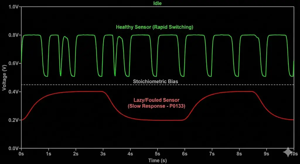
To confirm a "lazy" sensor suitable for cleaning, one must visualize its output using an OBDII scanner with live data graphing.
- Warm Up: Drive the vehicle for 15 minutes to reach closed-loop operation.
- Idle Test: Observe the voltage of O2S B1S1 (Bank 1 Sensor 1).
- Healthy: The voltage should oscillate rapidly between 0.1V and 0.8V. The frequency should be roughly 0.5Hz to 1Hz (switching every 1-2 seconds).
- Lazy (Carbon Fouled): The voltage hangs at one level for 3-4 seconds, then slowly ramps up or down. The waveform looks like rolling hills rather than sharp peaks.
- Snap Throttle Test: Briefly snap the throttle open and release.
- The sensor should immediately spike rich (>0.8V) on acceleration and drop lean (<0.1V) on deceleration (fuel cut).
- If the sensor reacts sluggishly (taking >1 second to respond to the throttle snap), it is confirmed as degraded and a candidate for cleaning.
Catalyst Efficiency Codes (P0420/P0430)
These codes relate to the downstream sensors (Sensor 2).
- Logic: The ECU compares upstream and downstream switching rates. If the downstream sensor switches as fast as the upstream sensor, the catalytic converter is not storing oxygen efficiently.
- Cleaning Relevance: Often, P0420 is blamed on a "bad sensor," but the sensor is usually telling the truth: the cat is dead. However, cleaning the downstream sensor can sometimes remove deposits that make it hypersensitive, temporarily resolving the code. "Mechanic in a bottle" solutions like Cataclean are often marketed for this specific scenario.
Ford-Specific Considerations: The F-150 and EcoBoost Ecosystem
Ford vehicles present unique challenges regarding O2 sensor maintenance. The engine bay packaging, particularly in the F-Series trucks, significantly influences the decision between cleaning (risking failure) and replacement (guaranteeing a fix but requiring difficult labor).
The 5.4L Triton (2004-2010): The "Passenger Side" Challenge
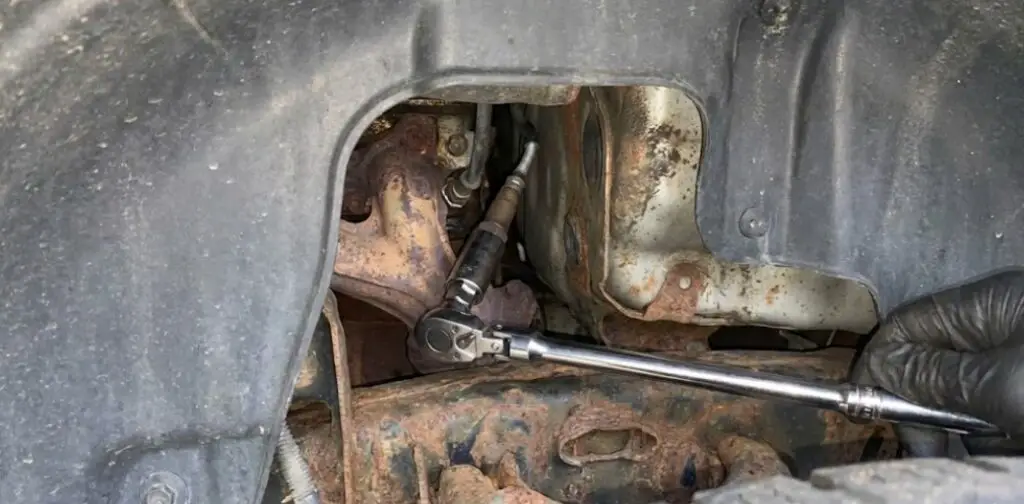
Owners of the 11th and 12th Generation F-150s with the 5.4L Triton V8 face a notorious maintenance hurdle: the Bank 1 Sensor 1 (Passenger Upstream) O2 sensor.
- Access: This sensor is located in a narrow corridor between the exhaust manifold, the transmission bell housing, and the firewall. It is virtually inaccessible from above.
- Removal Strategy: The accepted "Master" technique involves removing the front passenger wheel and the plastic wheel well liner (fender liner). This reveals a small triangular window through which the sensor is visible. Using a long extension (24"+) and a swivel joint with an O2 sensor socket is often required.
- Implication for Cleaning: Because the labor to remove this specific sensor is so high (1-2 hours for a novice), re-installing a cleaned sensor that might fail in a week is economically irrational. Recommendation: Always replace the Bank 1 Upstream sensor on a 5.4L Triton with a new Motorcraft unit once removed. Do not attempt to clean and re-use unless absolutely necessary.
The EcoBoost Era (2011-Present): Turbo Safety
The 3.5L and 2.7L EcoBoost engines introduce turbochargers and Gasoline Direct Injection (GDI) into the equation.
- GDI Soot: Direct injection engines produce significantly more particulate matter (soot) than port-injection engines because the fuel has less time to mix with air before combustion. This makes EcoBoost O2 sensors highly prone to carbon fouling, making them better candidates for cleaning than their port-injected predecessors.
- Turbo Risks: When using chemical cleaners (Method 1 below), concerns arise about turbo damage. However, reputable in-tank additives (PEA, Cataclean) are dissolved in the fuel and combusted. The exhaust gases passing through the turbine are chemically similar to normal exhaust, posing no risk to the turbocharger metallurgy.
- Wideband Sensitivity: As noted in Section 2.3, EcoBoost engines use upstream Wideband sensors. These are more expensive ($100-$150) but also more sensitive to damage. Physical cleaning (wire brushing) is strictly prohibited for these units.
Ford Connector "Red Tab" Syndrome
Ford O2 sensor connectors utilize a locking mechanism with a sliding red tab.
- The Problem: These tabs become brittle with heat and age. They often jam with road grit. Attempting to force them results in a broken connector lock, which can lead to the harness disconnecting during driving.
- The Solution: Before attempting to disconnect, spray the connector liberally with electrical contact cleaner or compressed air to dislodge grit. If the red tab breaks (common), the connector can still be secured using a zip-tie or by relying on the internal friction, though replacement of the pigtail is the "correct" repair.
Remediation Protocols: Comprehensive Cleaning Methodologies
If diagnostic testing confirms a "lazy" sensor, and the labor risk is deemed acceptable, several cleaning methodologies can be employed. These are ranked from least invasive (preventative) to most aggressive (restorative).
Method 1: In-Tank Chemical Remediation (Non-Invasive)
This method involves adding chemical detergents to the fuel tank. It cleans the sensor while the vehicle is driven. It is the only "Ford-safe" recommendation for preventative maintenance on EcoBoost engines.
Chemistry of Polyetheramine (PEA)
The most effective active ingredient for O2 sensor cleaning is Polyetheramine (PEA). Found in additives like Chevron Techron Concentrate Plus, Red Line SI-1, and Gumout Regane, PEA is a nitrogen-based detergent that is thermally stable.
- Mechanism: PEA does not burn up instantly in the combustion chamber. It survives the flame front to impact the exhaust valves and the O2 sensor face. It acts as a solvent for carbon deposits, slowly eroding the soot layer on the sensor ceramic.
- Protocol:
- Wait until the fuel tank is low (approx. 1/8 to 1/4 tank).
- Add a full bottle of high-PEA cleaner. This creates a hyper-concentrated cleaning solution.
- Drive the vehicle at highway speeds (sustained RPM) for 20-30 miles. High exhaust temperatures aid the chemical cleaning process.
- Refill the tank with Top Tier gasoline.
Catalytic Converter Cleaners (e.g., Cataclean)
Products like Cataclean are specifically formulated with organic solvents (Acetone, Xylene, Isopropanol) intended to vaporize and strip carbon from the post-combustion exhaust stream.
- Efficacy: Reviews and anecdotal evidence suggest a 50/50 success rate for clearing P0420 and P0133 codes. They are most effective on light carbon buildup but ineffective on sintered oil ash or silicone poisoning.
- Ford Suitability: Safe for use in F-150 and Explorer models, including EcoBoost, as they do not alter fuel viscosity significantly enough to harm high-pressure fuel pumps (HPFP) when used as directed.
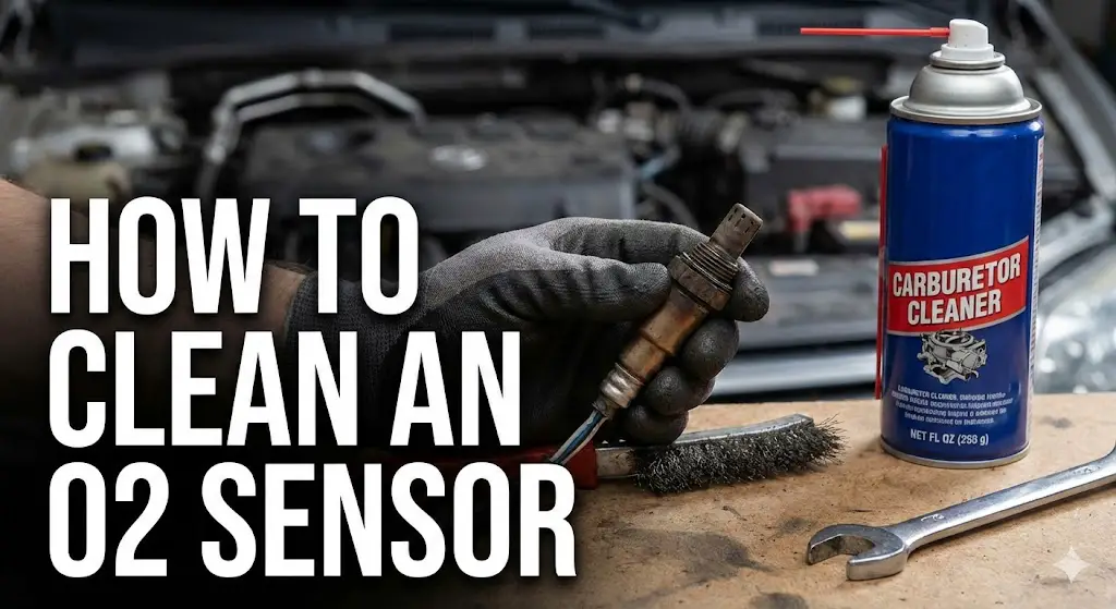
Method 2: Bench Cleaning with Solvents (Removal Required)
This is the standard DIY approach. It requires removing the sensor (see Section 7) and treating it externally.
Solvent Selection
- Gasoline: The sensor lives in a gasoline exhaust stream. Soaking the tip in fresh gasoline helps dissolve unburnt fuel varnish and soft soot. It is chemically safe for the sensor components.
- Carburetor Cleaner: Highly effective at dissolving carbon. However, some cheap cleaners leave a residue. Use a premium, low-residue cleaner.
- Acetic Acid (Vinegar) / Lemon Juice: Mild acids can remove mineral deposits (like those from slight coolant leaks) and light carbon. Soaking in warm vinegar for 10-20 minutes is a gentle "home remedy" that poses little risk to the ceramic.
- Hydrochloric Acid / Ferric Chloride: mentions using diluted acid. Warning: This is an industrial cleaning method. While it strips deposits aggressively, it risks etching the platinum electrode or corroding the internal connections inside the steel housing. Not recommended for the average DIYer.
The Procedure
- Safety: Wear nitrile gloves and eye protection. Work outdoors or in a ventilated garage.
- Soak: Fill a plastic container with the chosen solvent (Gasoline or Carb Cleaner). Suspend the sensor so that only the tip (the slotted metal shield) is submerged.
- CRITICAL: Do not submerge the wire harness or the top of the sensor body. Liquid entering the reference air vent (often near the wires) will permanently destroy the sensor.
- Duration: Soak for 4 to 8 hours (Gasoline) or 30-60 minutes (Carb Cleaner).
- Agitation: Swirl the sensor gently.
- Drying: Remove and shake dry. Allow to air dry for at least 2 hours. Ensure all solvent has evaporated. Installing a wet sensor into a hot exhaust can cause the ceramic to shatter due to thermal shock (rapid vaporization of the liquid).
Method 3: The "Blow Torch" Technique (Thermal Decarbonization)
This method is controversial but rooted in the principle that the O2 sensor is designed to operate at high heat.
- Theory: Carbon oxidizes (burns) at temperatures above $600^{\circ}C$. By heating the sensor tip to "cherry red" with a propane or MAP gas torch, one can incinerate the soot deposits that solvents cannot dissolve.
- Procedure:
- Secure the sensor in a vise (clamp the hex nut, not the body).
- Apply the torch flame to the tip. Move the flame constantly to avoid hot spots.
- Heat until the tip glows dull red. Hold for 30-60 seconds.
- Allow to air cool slowly. Do not quench in water.
- Risks:
- Heater Circuit Meltdown: The internal heating element is delicate. Excessive heat transfer can melt the wiring insulation or the filament itself, resulting in a dead sensor (P0135).
- Ceramic Fracture: Rapid heating or cooling cracks the Zirconia thimble.
- Verdict: This is a "Hail Mary" pass. Only use this if the sensor is already considered dead and you have a replacement ready if it fails.
Operational Procedures: Removal and Installation Best Practices
For the Ford owner, the physical removal of the sensor is often the most difficult part of the process. Exhaust cycles create rust and seizing that can turn a simple job into a nightmare.
Penetrating Chemistry
Do not attempt to remove a cold, dry O2 sensor.
- The "Secret Sauce": A 50/50 mix of Automatic Transmission Fluid (ATF) and Acetone is widely regarded in engineering circles as the most effective penetrating fluid, superior to commercial products.
- Commercial Options: Kroil and PB Blaster are the industry standards. WD-40 is a water displacer, not a penetrant; it is ineffective for exhaust rust.
- Protocol: Spray the sensor threads heavily the night before the repair. Spray again 1 hour before starting.
The "Heat and Beat" Strategy
- Thermal Expansion: If the sensor is stuck, run the engine for 5-10 minutes. The exhaust pipe (steel/cast iron) will expand slightly differently than the sensor, potentially breaking the rust bond. Caution: The pipe will be hot. Wear leather gloves.
- Vibration: Before applying turning force, tap the sensor body firmly with a hammer (if accessible) or an air hammer with a blunt tip. The vibration helps micro-fracture the rust scale.
Tooling Selection
- The Slotted Socket: The standard tool is a 7/8" (22mm) socket with a slot cut for the wire.
- Flaw: Under high torque, the slot causes the socket to spread open ("cam out"), rounding off the sensor hex nut.
- The Crowfoot / Offset Wrench: For stubborn sensors, use a specialized Offset O2 Sensor Socket (e.g., Lisle or OEM Tools). This design puts a solid ring of metal around the nut (with a side loop for the wire) and allows the use of a breaker bar without spreading the socket.
- Thread Chasing: If the old sensor drags threads out with it (galling), you must use an M18x1.5 thread chaser (not a tap) to clean the bung threads before installing the new/cleaned sensor.
Installation
- Anti-Seize: Apply high-temperature nickel or copper anti-seize to the threads.
- Warning: Do not get anti-seize on the sensor tip. Most anti-seize compounds contain conductive metals or silicates. If this touches the sensing element, it will poison the sensor immediately.
- Note: New Motorcraft sensors come with a dry, pre-applied anti-seize compound. Do not add more.
- Torque: Tighten to 30-35 ft-lbs (40-47 Nm). Over-tightening can deform the sensor body or strip the exhaust bung threads.
Economic and Risk Analysis: The "Repair vs. Replace" Equation
Is cleaning worth the effort? This depends on the value of the owner's time and the specific vehicle context.
Component Costs
- Motorcraft (OEM): The gold standard for Fords.
- Upstream (DY-835, DY-1120): $70 - $130.
- Downstream (DY-1093): $50 - $80.
- Bosch (OEM Supplier): Often the exact same part in a different box.
- Price: $50 - $90.
- Aftermarket (Walker/Cheap brands):$20 - $40.
- Risk: High failure rate. Ford ECUs are notoriously sensitive to the heater circuit resistance. Cheap sensors often trigger P0135 codes immediately.
The Cost of Failure
- Fuel Economy: A "lazy" sensor that is not yet throwing a code can cause the engine to run constantly rich. A 10% drop in fuel economy on a Ford F-150 (15 MPG average) translates to a loss of 1.5 MPG.
- Over 10,000 miles, this equals roughly 66 extra gallons of fuel.
- At $3.50/gallon, that is $231/year in wasted fuel.
- Conclusion: The cost of "limping along" with a dirty sensor for 6 months often exceeds the cost of a brand new Motorcraft sensor.
The Verdict on Cleaning
- Clean: If you have more time than money, or if the sensor is easy to access (e.g., downstream sensors). Using Method 1 (Fuel Additive) is always recommended as a first step.
- Replace: If the sensor is difficult to access (e.g., F-150 Passenger Upstream). The risk of having to do the job twice makes cleaning economically irrational for these locations.
Conclusion and Master Protocol
The remediation of automotive oxygen sensors is a nuanced topic where engineering theory meets roadside reality. While manufacturers like Ford and Bosch correctly state that a poisoned sensor cannot be saved, the reality of carbon fouling in high-mileage engines offers a window of opportunity for cleaning.
The FordMasterX Recommendation:
- Diagnose First: Confirm the issue is a "Response" issue (P0133/P0420) and not a "Heater" issue (P0135).
- Chemical First Strike: Treat a low fuel tank with a high-PEA additive (Techron/Red Line) and drive aggressively for 50 miles. This resolves roughly 30-40% of light fouling cases without lifting a wrench.
- Inspect: If removal is necessary, inspect the tip.
- White/Glazed: Discard. (Silicone Poisoned).
- Black/Sooty: Attempt a gasoline/solvent soak.
- Hardware: If replacing, stick to Motorcraft or Bosch units. Avoid "Universal" sensors that require wire splicing.
- Prevention: For EcoBoost owners, the regular use of Top Tier gasoline and occasional PEA additives is the best defense against the rapid carbon accumulation inherent to Direct Injection engines.