Ford Upfitter Switches Wiring Diagram: Easy Setup Guide
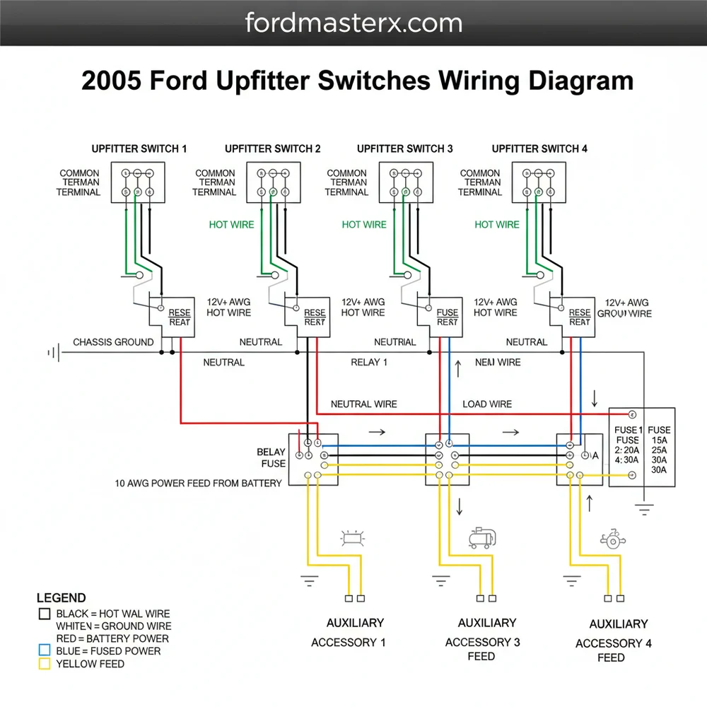
The 2005 Ford upfitter switch system connects four auxiliary switches to a dedicated relay box. Each switch sends power through a hot wire to a specific blunt-cut wire behind the dash. These wires are color-coded and fused to support different amperages, allowing you to power accessories by completing the circuit with a ground wire.
📌 Key Takeaways
- Provides a factory-integrated solution for powering aftermarket lights, winches, or tools.
- The four blunt-cut customer access wires are the most important components to identify.
- Always match accessory amperage to the specific fuse rating of the switch being used.
- Use the pass-through wires to avoid drilling new holes through the firewall.
- Consult this diagram when adding any high-draw electrical equipment to your Ford Super Duty.
The 2005 Ford Super Duty (F-250, F-350, F-450, and F-550) marked a significant era for truck enthusiasts, introducing more refined interior options and the highly sought-after factory upfitter switches. These switches, integrated directly into the dashboard, provide a clean, professional way to control high-amperage aftermarket accessories like off-road lighting, winches, air compressors, or even high-idle kits. For the DIY mechanic, understanding the 2005 Ford upfitter switches wiring diagram is the difference between a seamless, factory-finish installation and a tangled mess of wires under the dash. This guide provides a comprehensive breakdown of the wiring colors, circuit capacities, and locations to help you master your truck’s electrical system.
Main Components and Features
The upfitter switch system in a 2005 Ford is more than just four buttons on the dash; it is a fully integrated relay-controlled circuit system. Unlike basic toggle switches that you might buy at an auto parts store, the Ford system uses a dedicated relay box located behind the glove compartment or integrated into the main junction block. This design ensures that high-current loads are handled by heavy-duty relays rather than passing through the switch itself, protecting your interior components from heat and electrical failure.
The system consists of four primary components:
- The Switch Assembly: Located in the center dash, typically to the right of the steering column. These are four rocker switches labeled AUX 1 through AUX 4.
- The Relay Block: A dedicated cluster of four relays that receive the low-current signal from the dash switches and output high-current power to the accessories.
- The Blunt-Cut Pigtails: These are the “output” wires where you actually connect your accessories. In the 2005 model, these are located under the dashboard, taped to the main wire harness near the steering column or behind the fuse panel.
- Customer Access (Pass-Through) Wires: These are four additional wires that run through the firewall. They are not powered by the switches directly but act as a “bridge” to get your signals from the cabin to the engine bay without drilling new holes in the firewall.
How to Read the 2005 Upfitter Wiring Diagram

To successfully wire your accessories, you must identify the specific wire colors associated with each switch. Each switch has a different amperage rating, meaning you must match your accessory’s power draw to the correct circuit. Using a 30-amp light bar on a 10-amp circuit will result in blown fuses and potential wire damage.
The 2005 Ford Upfitter Switch color codes and ratings are as follows:
- AUX 1 (30 Amp): Orange with a Light Green stripe. This is the heavy-duty circuit intended for large light bars or small compressors.
- AUX 2 (30 Amp): Orange. Also a high-amperage circuit for power-heavy accessories.
- AUX 3 (10 Amp): Orange with a Yellow stripe. Best for smaller LED pods, interior lighting, or relay triggers for even larger systems.
- AUX 4 (10 Amp): Orange with a Light Blue stripe. Typically used for low-draw electronics or high-idle modifications.
When looking at the wiring diagram, you will notice that these wires are bundled together with “blunt-cut” ends. They are usually tucked high up under the dash, near the steering column. You may need to remove the lower dash panel (the plastic piece under the steering wheel) to find them. They are often wrapped in black electrical tape and may be difficult to spot at first glance.
Additionally, you must locate the Pass-Through Wires if your accessory is located in the engine bay. These four wires are typically colored:
- White
- Blue
- Red
- Black
These four wires exist in two places: inside the cabin near the upfitter pigtails, and under the hood, usually located near the master cylinder or the driver-side fender well. To use them, you connect your Upfitter wire (e.g., Orange/Green) to a Pass-Through wire (e.g., Red) inside the cabin. Then, under the hood, you connect your accessory to that same Red wire.
Step-by-Step Practical Guidance
For DIYers, the physical installation is often more challenging than understanding the diagram. Here is how to practically apply the wiring knowledge:
1. Locating the Wires
Start by sitting in the driver’s seat and looking under the dash. Remove the access panel below the steering column. Look for a bundle of wires with heat-shrink or taped ends that don’t seem to go anywhere. These are your blunt-cut pigtails. In the 2005 model, they are often tucked behind the Central Junction Box (the fuse box). You may need a flashlight and a pair of long-reach needle-nose pliers to gently pull them forward.
2. Preparing the Connection
Once you have identified the wire you need (e.g., AUX 1 Orange/Green for a light bar), strip back about 1/4 inch of insulation. Use a high-quality crimp connector or, preferably, a solder joint with heat-shrink tubing. Avoid using “T-taps” or “Scotch locks,” as these can vibrate loose in a diesel truck and cause intermittent power issues.
3. Managing the Ground
The Ford upfitter switches provide the positive (+) power. You must provide a solid ground for your accessory. For interior accessories, there are several factory ground bolts under the dash. For exterior accessories, ground them directly to the frame or a dedicated grounding block in the engine bay. Never assume a random bolt into plastic is a sufficient ground.
4. Fuse Verification
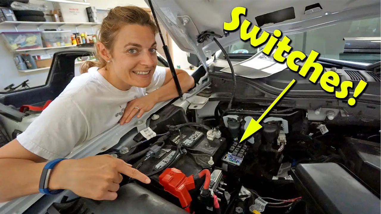
The fuses for the upfitter switches are located in the engine compartment power distribution box. If your switches don’t light up or provide power, check these fuses. For the 2005 model, they are usually fuses 3, 5, 7, and 9, but check your owner’s manual as mid-year production changes sometimes shifted these positions.
Installation Tips for Success
Working with the 2005 Ford electrical system requires patience. Here are some tips to make the job easier:
- Label Your Wires: Before you tuck everything back into the dash, wrap a piece of masking tape around your connections and label them (e.g., “AUX 1 – Fog Lights”). This will save you hours of headache if you need to troubleshoot later.
- Use Loom: When running wires from the pass-through pigtails in the engine bay to your lights or winch, use split-conduit wire loom. This protects the wires from the high heat of the 6.0L PowerStroke engine (or the V10/5.4L gas engines) and prevents rubbing against sharp metal edges.
- Dielectric Grease: If you are making connections under the hood, use a small amount of dielectric grease inside your connectors to prevent corrosion from road salt and moisture.
- The “Fishing” Technique: If you can’t find the pass-through wires under the hood, have a friend gently wiggle the wires from inside the cabin while you watch the area near the brake booster.
Troubleshooting Common Issues
Even with a perfect understanding of the diagram, issues can arise. Here is how to fix the most common 2005 Ford upfitter problems:
Switches Won’t Light Up
Each switch has a small amber indicator light. If these don’t light up when the key is “ON” and the switch is “UP,” the problem is likely the supply fuse or the relay. Check the main fuse box in the engine bay. Also, check the connector on the back of the switches themselves; sometimes, if the dash has been removed previously, the plug wasn’t seated fully.
Power is Present but Accessory Doesn’t Work
Use a multimeter or a test light at the blunt-cut pigtail. If you have 12V power there, the issue is further down the line. Most often, this is a poor ground at the accessory itself or a broken connection at the firewall pass-through wires.
Blown Fuses Immediately
If the fuse blows the moment you flip the switch, there is a short to ground. Check the entire length of your wire for any spots where the insulation might have rubbed through against the frame or firewall. Ensure that you haven’t exceeded the amperage limit (10A or 30A) for that specific switch.
Intermittent Power
This is almost always a loose crimp or a “cold” solder joint. Ford Super Duty trucks vibrate significantly, especially the diesel variants. Ensure all connections are mechanically secure and supported so they aren’t hanging by the wire weight alone.
By following this guide and referencing the 2005 Ford upfitter switches wiring diagram, you can take full advantage of your truck’s factory capabilities. Whether you’re setting up a work truck for the job site or an overlanding rig for the trails, these switches offer the most reliable and aesthetically pleasing way to power your gear.
Frequently Asked Questions
Where is the upfitter relay box located?
The relay box for the 2005 Ford upfitter switches is typically located behind the glove box or near the driver-side kick panel. It houses the four relays that handle the high-current draw for your accessories, keeping the heat and load away from the dashboard switches themselves.
What does the upfitter switches wiring diagram show?
This diagram illustrates the electrical path from the battery to the switch panel and out to the blunt-cut customer access wires. It identifies wire colors, fuse locations in the junction box, and how the hot wire provides power to your auxiliary components when the ignition is in the run position.
How many wires does each upfitter switch have?
Each switch connects to a specific wire in the harness. While a traveler wire setup isn’t standard here, each circuit features a hot wire output and shares a common terminal for power input. There are four main output wires, each color-coded to distinguish different circuits and amperage capacities.
What are the symptoms of a bad upfitter switch?
Symptoms include accessories not receiving power despite the switch being engaged or the indicator light failing to illuminate. If the ground wire is loose or a fuse is blown, the circuit won’t complete. Use a multimeter to check for voltage at the blunt-cut ends behind the dashboard.
Can I install upfitter switches myself?
Yes, installing the 2005 Ford upfitter switches is a popular DIY project for Super Duty owners. The process involves mounting the switch bank, connecting the harness to the relay box, and grounding the system. It is straightforward as long as you follow the wiring diagram to ensure proper polarity.
What tools do I need for this wiring task?
You will need a basic socket set to remove dash panels, a wire stripper, and crimping tools for connectors. A multimeter is essential to verify the hot wire and neutral wire connections. Heat shrink tubing is also recommended to ensure all connections remain waterproof and vibration-resistant over time.


