Ford Stereo Wiring Color Code Diagram: Easy Setup Guide
Ford stereo wiring color code diagrams map out the electrical pins for speakers, power, and illumination. Typically, the black ground wire connects to the chassis, while the yellow hot wire provides constant power. Understanding these colors ensures you match the correct common terminal to your aftermarket harness for a reliable audio setup.
📌 Key Takeaways
- Identifies pinout positions for power, ground, and speakers
- Critical to distinguish between constant and switched 12V power
- Safety requires disconnecting the battery before starting
- Using a harness adapter preserves factory wiring integrity
- Essential for installing aftermarket head units or amplifiers
Upgrading your vehicle’s audio system often begins with the daunting task of deciphering a complex bundle of factory cables. If you are looking for a reliable diagram ford stereo wiring color code, you are likely in the process of replacing a factory head unit with an aftermarket system or troubleshooting a loss of audio. Having the correct diagram is essential because Ford has utilized various harness configurations over the years, and a single misplaced connection can lead to short circuits or damage to your vehicle’s Engine Control Unit (ECU). In this comprehensive guide, you will learn how to identify each specific wire by its color and function, understand the pinout locations on the primary harness, and master the proper sequence for a safe and successful installation.
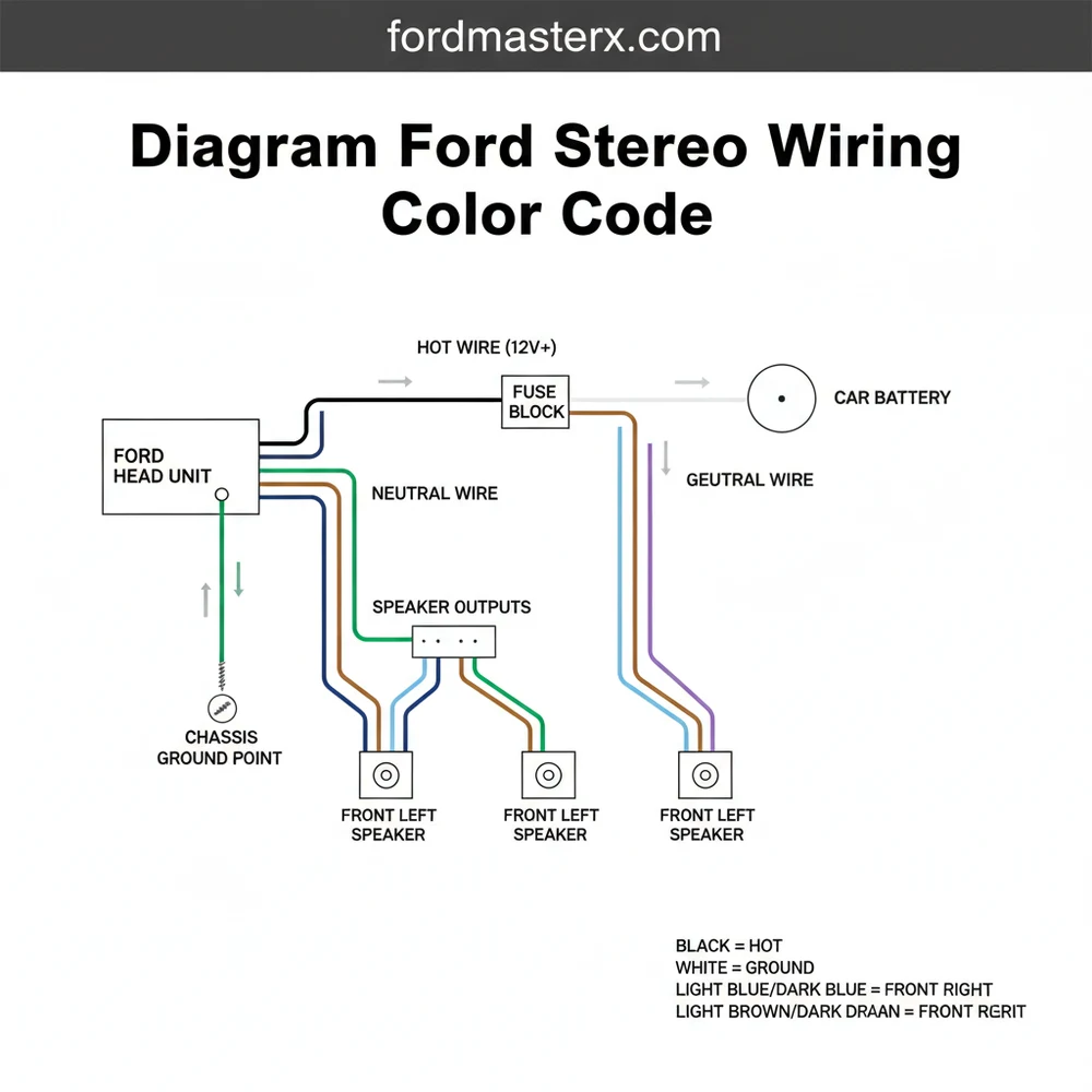
The standard diagram ford stereo wiring color code is designed to separate power delivery from signal output. In most Ford vehicles, the harness is divided into two or three primary sections: the power/ground block and the speaker signal block. The power section typically features the hot wire, which provides a constant 12V charge to maintain memory settings, and the ignition wire, which provides voltage only when the key is turned. The ground wire is almost always a solid black or black-and-green wire that connects to the vehicle’s chassis. Unlike residential electrical systems that use a brass screw or a neutral wire to complete a circuit, automotive systems rely on the metal body of the car as a common terminal for grounding.
[DIAGRAM_PLACEHOLDER: FORD STEREO WIRING PINOUT AND COLOR CHART]
Primary Power Connections:
- Yellow or Light Green/Purple: Constant 12V (Hot Wire)
- Red or Pink/Black: Switched Ignition (12V Accessory)
- Black or Black/Green: Ground Wire
- Blue or Blue/White: Power Antenna / Amp Remote Turn-on
Speaker Output Connections:
- White: Front Left (+)
- White/Black: Front Left (-)
- Gray: Front Right (+)
- Gray/Black: Front Right (-)
- Green: Rear Left (+)
- Green/Black: Rear Left (-)
- Purple: Rear Right (+)
- Purple/Black: Rear Right (-)
When interpreting the diagram, it is important to note that Ford often uses “twisted pairs” for speaker wires to reduce electromagnetic interference. While a household circuit might use a traveler wire for multi-switch configurations, automotive audio systems use dedicated positive and negative leads for each channel. The gauge of these wires is typically 18 or 20 AWG, which is sufficient for standard signal transmission but may need to be upgraded if you are installing high-wattage external amplifiers.
Always verify your specific model year’s pinout with a multimeter. While Ford follows a general color standard, premium sound systems like Sony, Mach, or THX often utilize different color schemes for their dedicated amplifier communication lines.
To ensure a professional installation using your diagram ford stereo wiring color code, follow these steps in the precise order listed below:
- Disconnect the Negative Battery Terminal: Before touching any wiring, use a 10mm wrench to disconnect the negative battery cable. This prevents accidental shorts that could blow fuses or damage the vehicle’s computer system while you are identifying the hot wire.
- Expose the Factory Harness: Use a plastic trim tool to remove the dashboard panels surrounding the stereo. Once the mounting screws are removed, pull the head unit forward and depress the locking tabs on the factory wiring harnesses to disconnect them.
- Match the Color Codes: Compare the wires on your new aftermarket harness to the factory colors listed in the diagram. If you are using a “plug-and-play” adapter, the colors usually match perfectly (e.g., Yellow to Yellow, Red to Red). If you are splicing directly, ensure you identify the common terminal for the ground connection.
- Prepare the Connections: Strip approximately half an inch of insulation from each wire. Ensure the wire gauge is consistent across your splices to maintain stable voltage. Avoid using electrical tape alone; instead, use crimp connectors or solder followed by heat shrink tubing.
- Identify Power and Ground: Connect the ground wire first to establish a safe path for current. Follow this by connecting the constant 12V hot wire and then the switched ignition wire. In Ford systems, the ignition wire is what triggers the unit to turn on, while the constant wire maintains your radio presets.
- Wire the Speaker Channels: Connect the four pairs of speaker wires. Be very careful to maintain polarity (matching the solid color to the positive and the striped color to the negative). Reversing polarity will cause the speakers to be “out of phase,” resulting in thin, weak bass response.
- Insulate and Secure: Use cable ties to bundle the wires neatly. This prevents the harness from rattling behind the dashboard or getting caught on moving parts like the climate control linkages. Ensure no copper is exposed to prevent shorting.
- Test the System: Reconnect the battery terminal. Turn the ignition to the “ACC” position. The stereo should power on. Test the fader and balance controls to ensure each speaker is in the correct location according to your diagram.
Never connect the constant hot wire directly to the ignition wire. This will bypass the vehicle’s power management system and will likely result in a parasitic drain that kills your battery overnight.
Even with a perfect diagram ford stereo wiring color code, you may encounter common issues during the installation. One of the most frequent problems is a “no power” situation. This is often caused by a blown fuse in the vehicle’s interior fuse box rather than a wiring error. If the stereo turns on but does not save your settings (like clock time or radio stations), you have likely swapped the constant hot wire with the switched ignition wire.
Another common issue is a loud “pop” sound when the car starts. This usually indicates that the remote turn-on wire for an external amplifier is receiving a voltage spike. In some Ford models, the factory amplifier requires a 5V turn-on signal rather than the standard 12V provided by aftermarket radios. Using a 12V signal on a 5V logic circuit can damage the factory amp. If you experience no sound despite the radio being powered on, check if your Ford came with a factory-amplified system, as you may need to trigger the “Amp Remote” wire to activate the speakers.
When testing wires, use a digital multimeter rather than a test light. Modern Ford vehicles use sensitive data lines (CAN-bus). A traditional bulb-style test light can draw too much current and potentially fry a communication module.
To ensure long-term reliability of your audio system, follow these best practices for wiring maintenance and quality. First, always use high-quality oxygen-free copper (OFC) wire if you need to extend any leads. Lower-quality aluminum wire (CCA) has higher resistance and can lead to voltage drops. When making connections, remember that the ground wire is the most important part of the circuit. A loose ground is the primary cause of “alternator whine,” that high-pitched buzzing sound that increases with engine RPM.
- ✓ Use a dedicated wiring harness adapter to avoid cutting the factory plugs.
- ✓ Label each wire with masking tape before final assembly to simplify future troubleshooting.
- ✓ Apply a small amount of dielectric grease to the harness pins to prevent corrosion in humid climates.
- ✓ Ensure the wire gauge matches the fuse rating of your new stereo.
In summary, mastering the diagram ford stereo wiring color code is the key to a successful DIY audio project. By identifying the specific functions of the hot wire, ground wire, and speaker leads, you can avoid the common pitfalls that lead to electrical failure. Whether you are dealing with a standard setup or a complex amplified system, taking the time to map out your connection points will ensure that your vehicle remains safe and your music sounds crystal clear. Always prioritize secure connections over speed, and never hesitate to consult a professional if your vehicle’s wiring does not match standard color expectations.
Step-by-Step Guide to Understanding the Ford Stereo Wiring Color Code Diagram: Easy Setup Guide
Identify the factory harness and match it to the Ford stereo wiring color code diagram for your model.
Locate the black ground wire and the constant 12V hot wire to provide stable power to the unit.
Understand how each traveler wire or signal lead connects to the specific speaker outputs on the common terminal.
Connect the neutral wire counterparts for each speaker to ensure the audio phase and polarity are correct.
Verify that the remote turn-on lead and illumination wires are properly spliced to prevent battery drain issues.
Complete the installation by securing the head unit in the dash and testing all audio channels for clarity.
Frequently Asked Questions
Where is the radio harness located?
The radio harness is located directly behind the dashboard’s center console panel. It is plugged into the rear of the factory head unit. To access it, you typically need to remove the dash trim pieces using specialized plastic pry tools to avoid damaging the interior surface.
What does the wiring diagram show?
The diagram shows the specific function of every wire in the vehicle’s audio plug. It identifies the hot wire for power, the ground wire for the circuit completion, and the specific color pairs for the front and rear speakers to ensure proper audio phase and balance.
How many connections does the harness have?
Standard Ford harnesses usually feature between 16 and 24 pins, depending on the trim level and premium audio options. These connections include a common terminal for speaker negatives and specialized leads for features like steering wheel controls, illumination dimming, and the power antenna signal.
What are the symptoms of a bad stereo wiring connection?
Common symptoms include the stereo failing to turn on, intermittent sound cutouts, or blown fuses. If the hot wire touches a metal surface, it can cause a short circuit. Static or popping sounds often indicate a loose traveler wire or a poorly grounded common terminal.
Can I install an aftermarket stereo myself?
Yes, installing a stereo is a manageable DIY task. By following a Ford stereo wiring color code diagram and using a vehicle-specific adapter, you can avoid cutting factory wires. This ensures a clean installation and makes it easier to revert to the factory setup later if needed.
What tools do I need for this task?
You will need a basic set of tools including a panel removal kit, a socket set (usually 7mm or 10mm), wire strippers, and crimp connectors or a soldering iron. A multimeter is also highly recommended to verify the voltage on the hot wire before making permanent connections.


