Ford Steering Column Wiring Diagram: Easy Setup Guide
A Ford steering column wiring diagram maps the connections for the ignition switch, turn signals, and horn. It identifies the hot wire supplying power, the ground wire for circuit completion, and specific safety circuits like the neutral wire. This guide ensures correct pin identification for repairs using the traveler wire paths.
📌 Key Takeaways
- Facilitates accurate mapping of signal and ignition paths for electrical repair
- Identify the primary hot wire to prevent accidental short circuits during testing
- Always disconnect the battery before handling steering column wiring to avoid airbag deployment
- Utilize the common terminal to verify continuity across multi-function switch positions
- Essential for restoring functionality to the horn, wipers, and neutral wire safety circuits
Navigating the intricate electrical web of a vehicle requires precision, especially when dealing with the central hub of driver input. Accessing a correct ford steering column wiring diagram is the essential first step for any enthusiast or mechanic looking to repair a faulty turn signal, replace an ignition switch, or upgrade to a modern tilt-style column. Having the right visual and technical data ensures that you do not accidentally cross circuits, which could lead to blown fuses or damaged components. In this guide, you will learn how to identify specific wire colors, understand terminal functions, and execute a sequence of connections that ensures your vehicle remains safe and functional on the road.
Most Ford steering columns from the classic era through the late 1990s follow a standardized color-coding system, but always verify your specific model’s gauge requirements to prevent overheating wires.
Decoding the Ford Steering Column Wiring Diagram
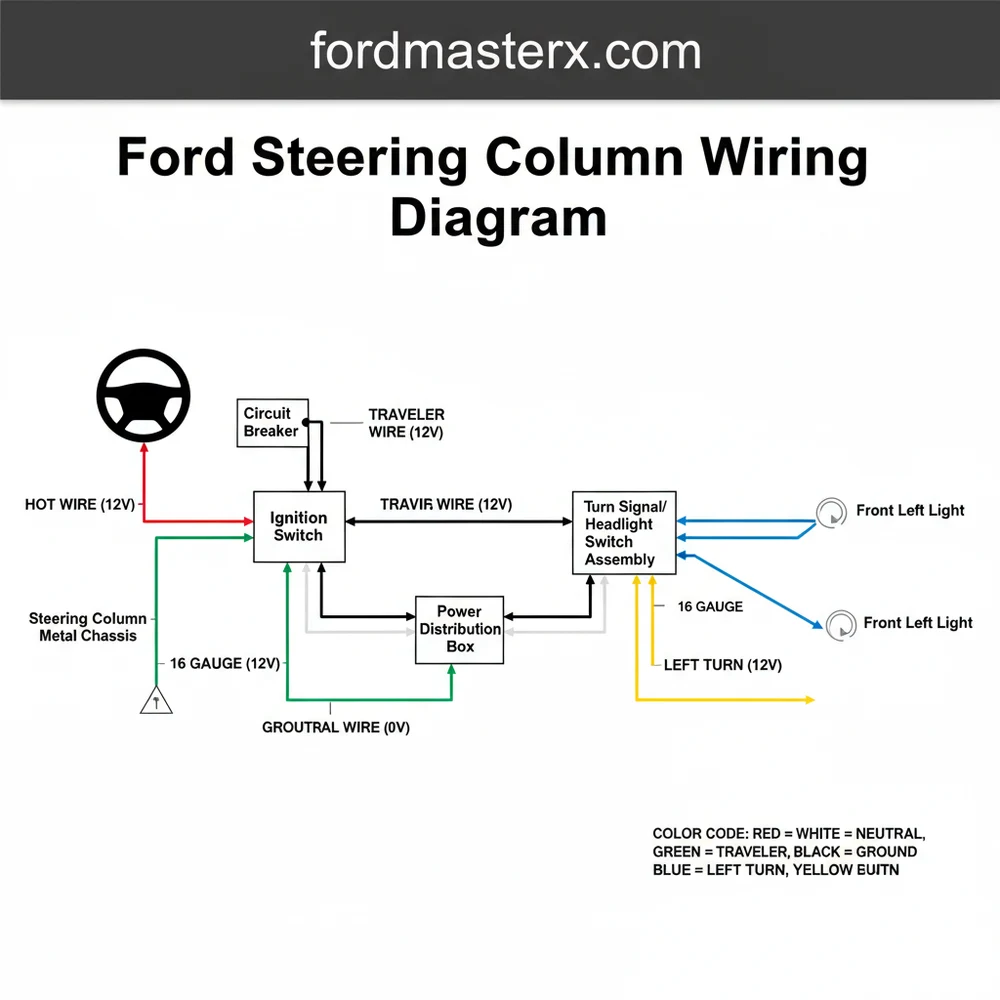
The ford steering column wiring diagram acts as a roadmap for the complex intersection of the turn signal switch, hazard lights, horn, and ignition system. At the heart of this diagram is the main harness connector, often referred to as the “harmonica connector” due to its long, flat shape. This component serves as the bridge between the internal column switches and the main vehicle wiring loom.
In a typical diagram, you will find several key elements. The hot wire, usually a thick yellow or red wire, provides constant 12-volt power to the ignition switch. This wire must be of a heavy enough gauge to handle the high current draw required during the starting sequence. Conversely, the ground wire provides the necessary return path for the circuit, often connecting to the metal frame of the steering column itself.
A critical component often highlighted in these diagrams is the common terminal within the turn signal switch. This terminal receives power from the flasher unit and distributes it to the left or right signals depending on the lever position. While residential electrical systems use a traveler wire for multi-way switching, in an automotive steering column, the signal wires act in a similar fashion, “traveling” from the switch to the front and rear bulb sockets. You will also notice the neutral wire configuration, specifically relating to the neutral safety switch, which ensures the vehicle only starts when the transmission is in park or neutral.
The visual layout usually separates the ignition functions from the lighting functions. For older models, you might see connections involving a brass screw on the horn relay or ignition housing, which provides a durable contact point for high-use components. Understanding these variations is vital because a 1970s truck column will have a significantly simpler pinout than a 1990s sedan equipped with cruise control and an airbag clock spring.
Step-by-Step Guide to Interpreting and Installing Column Wiring
Reading a ford steering column wiring diagram is a skill that combines technical observation with systematic execution. Follow these steps to ensure a professional-grade installation or repair.
- ✓ Multimeter or 12V Test Light
- ✓ Wire Strippers and Crimpers
- ✓ Heat Shrink Tubing
- ✓ Electrical Contact Cleaner
- ✓ Replacement Terminals (Pins or Spades)
1. Disconnect the Battery: Before touching any part of the steering column electrical system, disconnect the negative battery cable. This prevents accidental short circuits that could trigger the horn, blow the main fusible link, or in newer models, deploy the airbag.
2. Identify the Hot Wire and Power Source: Locate the heavy-gauge yellow wire on your diagram. This is your primary hot wire. Use your multimeter to verify that this wire has constant 12V voltage when the battery is connected (for testing purposes only). Once identified, ensure this wire is seated firmly in the main connector block.
3. Map the Turn Signal Circuit: Locate the common terminal on the harmonica connector. Standard Ford colors often use a Light Blue wire for the right front turn signal and a White/Blue stripe wire for the right rear. The left side typically utilizes Light Green and Green/Orange wires. Reference your diagram to match these colors to the correct pins on the vehicle-side harness.
4. Establish a Solid Ground: The ground wire is frequently overlooked. On Ford columns, the steering shaft and housing often serve as a ground path, but a dedicated black or green/white wire may be present. Ensure any brass screw terminals used for grounding are clean and free of corrosion to maintain a low-resistance path.
5. Integrate the Neutral Safety Circuit: If your column includes a shifter, identify the neutral wire pair. These wires must be connected to the transmission switch or the starting relay. This circuit prevents the “hot” signal from reaching the starter solenoid unless the “neutral” condition is met, providing an essential safety barrier.
6. Final Pin Inspection and Connection: Before snapping the connectors together, inspect each pin. Ensure no pins are bent or pushed back. If you are using a conversion harness, check that the wire gauge matches the factory specifications to prevent voltage drops that can dim your lights or cause slow turn signal flashing.
Never bypass the neutral safety switch by jumping the wires. This allows the vehicle to start in gear, which can lead to serious injury or property damage.
Common Issues and Troubleshooting

Even with a high-quality ford steering column wiring diagram, you may encounter obstacles. One of the most frequent issues is a “phantom” turn signal problem where one side works, but the other causes all lights to flash. This is often a sign of a bad ground wire or a crossed wire at the common terminal.
Another common failure point is the ignition switch connector. Over time, the high voltage passing through the hot wire can generate heat, leading to melted plastic around the terminals. If your vehicle intermittently loses power to the dashboard or fails to crank, inspect the connector for signs of browning or brittle insulation. Using a multimeter, check the voltage at the output side of the switch; if it is significantly lower than the battery voltage, the switch or the connector has high resistance and needs replacement.
If the horn sounds continuously or not at all, the issue usually lies with the horn brush or the contact ring inside the column. The diagram will show a single wire (often Dark Blue or Yellow) that provides a ground trigger for the horn relay. If this wire touches the steering shaft, the horn will stay on.
Tips and Best Practices for Wiring Success
To achieve a long-lasting repair, always use high-quality components. When replacing sections of the harness, ensure the wire gauge is identical to the original. Using a wire that is too thin increases resistance, which can lead to heat buildup and eventually a fire.
Apply a small amount of dielectric grease to the connector pins before final assembly. This prevents moisture intrusion and stops corrosion before it starts, which is especially important in humid or coastal climates.
Maintenance of the steering column should also include a periodic check of the wire routing. Ensure the harness is secured with zip ties and is not rubbing against the sharp edges of the dashboard or the moving parts of the brake pedal assembly. Friction can wear through the insulation, creating a short to ground that can be incredibly difficult to track down later.
When sourcing parts, look for OEM-spec connectors. While generic spade terminals can work in an emergency, the proper “harmonica” style connector provides a much more secure and vibration-resistant connection. If you are working on a classic restoration, seek out diagrams that specifically show the brass screw locations for the turn signal cam, as these are often different from modern plastic snap-in versions.
By following the ford steering column wiring diagram closely and adhering to these technical standards, you can ensure that your vehicle’s electrical system is reliable, safe, and easy to maintain for years to come. Whether you are chasing a short circuit or installing a custom column, the key lies in the details of the wire colors and the integrity of your connections.
Frequently Asked Questions
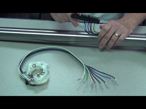
Where is the steering column wiring harness located?
The main wiring harness is located directly underneath the steering column shroud, typically accessible by removing several Phillips head or Torx screws. The connector block sits near the base of the column, where it transitions into the main dash harness for distribution to various electronic modules and switches.
What does a Ford steering column wiring diagram show?
A Ford steering column wiring diagram illustrates the electrical pathways for the horn, turn signals, wipers, and ignition system. It displays how power moves from the battery through the fuse box to the multi-function switch, ensuring that every driver input translates into the correct vehicle response.
How many wire connections does a Ford steering column have?
Most Ford columns feature between 8 and 12 wires depending on features like cruise control. The hot wire provides constant power, while the common terminal distributes current to the turn signals. You will also find specific outputs for the hazard lights and the vital steering column ground wire connection.
What are the symptoms of a bad steering column wiring harness?
Symptoms include flickering dashboard lights, non-functional turn signals, or a horn that works intermittently. You may also experience a vehicle that fails to crank if the ignition switch wiring is frayed, or if the neutral wire circuit for the safety switch has been compromised by heat or vibration.
Can I replace Ford steering column wiring myself?
Yes, repairing steering column wiring is a feasible DIY task if you have a reliable diagram. By following the color-coded paths for the ground wire and signal outputs, most enthusiasts can successfully swap switches or repair damaged connectors without professional electrical training or expensive specialized diagnostic equipment.
What tools do I need for Ford steering column wiring repair?
To work on Ford steering column wiring, you will need a digital multimeter for continuity testing, a set of screwdrivers or Torx bits to remove the shroud, and wire strippers. A test light is also helpful for quickly identifying which pin acts as the primary hot wire.


