Ford Steering Column Parts Diagram: Complete Guide
A Ford steering column parts diagram illustrates the assembly of the upper and lower shafts, clock spring, ignition cylinder, and multifunction switches. It serves as a visual map for identifying mechanical hardware and sensors that communicate with the ECU, helping you locate the source of steering play or electrical faults.
📌 Key Takeaways
- Detailed visual map of all internal steering assembly components
- Essential for identifying the clock spring and steering angle sensor
- Safety warning: Always disconnect the battery when working near airbags
- Cross-reference diagram numbers with OEM parts for perfect fitment
- Ideal for troubleshooting mechanical looseness or electronic signal failures
Navigating the intricate internals of a vehicle’s cabin can be a daunting task for even the most seasoned DIY mechanic. When you are faced with a stiff steering wheel, a malfunctioning ignition, or flickering dashboard lights, a detailed ford steering column parts diagram becomes an indispensable resource for your repair arsenal. This comprehensive guide is designed to help you decode the complexities of the steering assembly, providing a clear roadmap from the steering wheel down to the intermediate shaft. By understanding the relationship between mechanical linkages and electronic sensors, you will gain the confidence to identify components, interpret professional schematics, and perform precision repairs that restore both the safety and drivability of your vehicle.
Understanding the Anatomy of the Steering Column
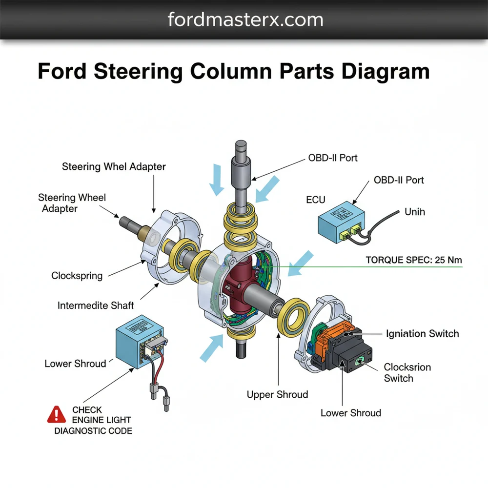
A professional-grade ford steering column parts diagram serves as a visual inventory of the components that translate your physical input into directional movement. The assembly is generally divided into three main sections: the upper housing, the main shaft, and the lower steering linkage. At the top of the column, you will find the steering wheel mounting point and the clock spring. The clock spring is a critical ribbon-like electrical connector that allows the steering wheel to rotate while maintaining a constant electrical connection for the airbag, horn, and cruise control buttons. If this component fails, you may see a check engine light or an airbag warning light on your instrument cluster.
Most modern Ford steering columns are designed as “collapsible” units. This is a safety feature that allows the column to compress during a front-end collision, preventing the shaft from being pushed into the driver’s chest. Always handle the main shaft with care during removal to avoid triggering the internal collapse mechanism.
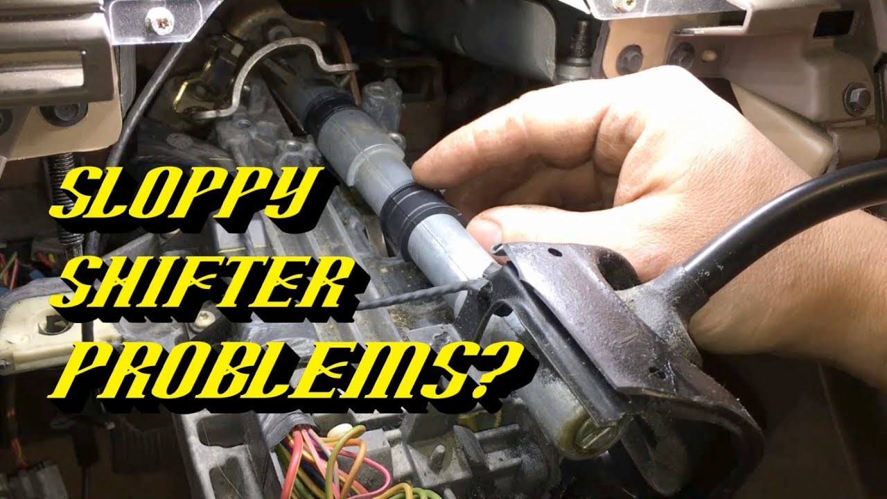
Moving down the column, the diagram typically highlights the ignition switch and the lock cylinder housing. In vehicles equipped with column-mounted shifters, the assembly also includes the shift tube and bushings, which are notorious for wearing out and causing a “sloppy” gear selector feel. The central portion of the diagram illustrates the steering shaft itself, which is often supported by upper and lower bearings. These bearings ensure smooth rotation and prevent the shaft from vibrating against the outer housing. Finally, the column connects to the intermediate shaft via a universal joint (U-joint). This joint is the bridge between the interior cabin and the engine bay, eventually leading to the steering rack or gear box.
Visual variations are common depending on whether the vehicle features a tilt-and-telescoping function or a fixed column. Tilt columns include an additional pivot pin and a tension spring mechanism that allows for height adjustment. When reviewing your specific ford steering column parts diagram, pay close attention to the explode-view lines that indicate the order of washers, snap rings, and shims, as these small parts are essential for eliminating “play” or vertical movement in the wheel.
[DIAGRAM_PLACEHOLDER: A high-resolution exploded view of a Ford steering column, showing the steering wheel, clock spring, multifunction switch, ignition lock cylinder, main shaft, tilt mechanism, and the intermediate shaft connection. Components are labeled with numerical callouts corresponding to a parts list.]
Step-by-Step Guide to Interpreting and Using the Diagram
Using a diagram effectively requires more than just looking at the pictures; it requires a systematic approach to disassembly and diagnosis. Follow these steps to ensure a successful repair process while maintaining the integrity of your vehicle’s electronic systems.
- ✓ Step 1: Secure the Electrical System – Before touching any component near the steering wheel, disconnect the negative battery terminal and wait at least 15 minutes. This allows the capacitors in the airbag system to discharge, preventing accidental deployment.
- ✓ Step 2: Access the Diagnostic Port – If you are troubleshooting an electrical issue, plug in a scanner to the OBD-II port. Look for a specific diagnostic code related to the steering angle sensor or the ECU. This data will tell you if the problem is a physical part on the diagram or an electronic communication error.
- ✓ Step 3: Remove the Outer Shrouds – Use the diagram to locate the hidden screws holding the plastic column covers together. These are often recessed and require a long-reach Phillips or Torx driver.
- ✓ Step 4: Identify Part Numbers – Cross-reference the callout numbers on your ford steering column parts diagram with the manufacturer’s part list. This ensures you order the exact revision for your specific trim level, especially for components like the multifunction switch which controls wipers and turn signals.
- ✓ Step 5: Inspect Mechanical Joints – Check the U-joints on the intermediate shaft for rust or binding. If the steering feels “notchy,” the diagram will show you where the pinch bolts are located. These bolts must be tightened to a specific torque spec to prevent the shaft from disconnecting while driving.
- ✓ Step 6: Reassembly and Calibration – Once parts are replaced, follow the diagram in reverse order. If you replaced the steering angle sensor, you may need to perform a “re-learn” procedure through the ECU so the vehicle knows the exact center point of the steering wheel.
Never attempt to force the steering wheel off the shaft without a proper puller tool. Using a hammer can damage the sensitive bearings and internal plastic clips shown in the diagram, leading to permanent column failure.
Common Steering Column Issues & Troubleshooting

One of the most frequent problems Ford owners face is a “clunking” or “popping” sound when turning the wheel. By referring to your ford steering column parts diagram, you can isolate this noise to the intermediate shaft or the lower column bearing. If the noise disappears when you adjust the tilt position, the issue likely lies within the tilt pivot pins or the internal tension springs. Another common symptom is the failure of steering wheel buttons or the horn. This almost always points to the clock spring, an electronic bridge located directly behind the steering wheel hub.
Electrical gremlins can also manifest as a check engine light or a “Service Power Steering” message. In these cases, the physical diagram helps you trace the wiring harnesses that lead from the column to the main vehicle computer. Use your OBD-II scanner to pull a diagnostic code; for example, codes in the U-series often indicate a loss of communication between the column sensors and the ECU. If you find evidence of burnt wires or loose pins in the connectors shown on the diagram, you may need to repair the harness rather than replacing mechanical components.
Maintenance Tips and Professional Best Practices
While the steering column is largely a “set it and forget it” component, long-term vehicle health requires a holistic approach to maintenance. When you have the vehicle in the shop for steering work, it is a prime opportunity to inspect other critical systems. For instance, check the accessory belt for cracks or glazing, as this belt drives the power steering pump in older models. Similarly, verifying proper coolant flow through the heater core hoses—which often run near the steering shaft firewall entry—can prevent future leaks that might damage the lower steering column seals.
When replacing the intermediate shaft, apply a small amount of high-temp lithium grease to the splines before assembly. This prevents future corrosion and makes it significantly easier to remove the shaft the next time service is required.
Always prioritize high-quality OEM or equivalent components. While aftermarket parts may be cheaper, steering is a safety-critical system where precision matters. Ensure every bolt is tightened to the manufacturer-recommended torque spec. For those working on high-mileage vehicles, also take a moment to inspect the timing chain area for oil leaks that could drip onto the steering rack or lower column bushings. Oil exposure causes rubber components to swell and degrade prematurely. By using a ford steering column parts diagram as your foundational guide, you ensure that every repair is accurate, safe, and built to last. Whether you are dealing with a simple mechanical rattle or a complex electronic fault, having the right schematic ensures you spend less time guessing and more time driving.
Frequently Asked Questions
Where is the steering angle sensor located?
The steering angle sensor is typically located inside the column assembly, positioned behind the steering wheel and clock spring. It tracks the wheel’s rotation and sends data to the ECU. A failure here often triggers a check engine light or stability control warning on your dashboard instrument cluster.
What does a Ford steering column parts diagram show?
This diagram provides a detailed exploded view of the steering column’s mechanical and electrical architecture. It highlights the upper and lower shafts, bearings, ignition lock housing, and multifunction stalks. This visualization is critical for understanding how the column interacts with the vehicle’s computer and various electronic control systems.
How many electrical connections does the column have?
Most modern Ford steering columns feature between four and eight primary electrical connectors. These include the ignition switch, clock spring for airbag and horn, turn signal stalks, and the steering angle sensor. Each connection must be securely seated to avoid generating a diagnostic code during a system scan.
What are the symptoms of a bad steering column?
Common symptoms include grinding noises during turns, excessive steering wheel play, or a tilting mechanism that won’t lock. Additionally, electrical issues like a non-functional horn or a persistent check engine light may indicate a failed clock spring or internal wiring harness damage within the column assembly.
Can I replace steering column parts myself?
Yes, many parts like the turn signal switch or ignition cylinder are DIY-friendly. However, tasks involving the airbag or internal bearings require caution. Always use an OBD-II scanner to clear codes after the repair is finished and ensure you have the correct tools to handle sensitive internal components.
What tools do I need for steering column repair?
You will need a basic socket set, Torx drivers, a steering wheel puller, and a torque wrench. Because precision is vital for safety, you must follow the specific torque spec for the main mounting bolts. An OBD-II tool is also helpful for resetting any electronic fault codes.


