Ford Ranger Automatic Transmission Diagram Guide
A Ford Ranger automatic transmission diagram illustrates the layout of internal gears, clutches, the valve body, and external sensors. It maps the critical connections between the transmission and the ECU, helping you trace hydraulic paths and electrical signals to diagnose shifting delays or fluid leaks accurately without professional help.
📌 Key Takeaways
- Visualizes the internal and external component layout for effective troubleshooting.
- Identifies the valve body and solenoid pack as the primary control center.
- Always secure the vehicle on jack stands before performing under-car inspections.
- Use the diagram to locate specific diagnostic pins for multimeter testing.
- Reference this guide when experiencing slipping gears or fluid discoloration.
Understanding the internal architecture of a vehicle is the first step toward successful DIY maintenance or professional-grade repair. For many owners, a detailed ford ranger automatic transmission diagram serves as the essential roadmap to navigating the complex hydraulic and mechanical systems that keep the truck moving. Whether you are dealing with slipping gears or an unexpected warning light on the dashboard, having a high-quality visual reference ensures you can identify parts accurately before turning a wrench. This guide will walk you through the core components, diagnostic procedures, and maintenance protocols required to keep your Ford Ranger’s powertrain performing at its peak.
The ford ranger automatic transmission diagram typically illustrates a longitudinal layout, which is standard for rear-wheel and four-wheel-drive trucks. At the front of the diagram, you will find the torque converter, a critical component that acts as a fluid coupling between the engine’s crankshaft and the transmission’s input shaft. Moving inward, the diagram highlights the pump assembly, which is responsible for generating the hydraulic pressure necessary for gear engagement and lubrication.
One of the most complex areas in the diagram is the valve body. Often described as the “brain” of the unit, the valve body contains an intricate maze of channels and solenoids. These solenoids receive electrical pulses from the ECU (Engine Control Unit) to direct fluid flow to specific clutch packs or bands. Visual charts usually employ color-coding to help users distinguish between high-pressure supply lines and low-pressure return lines. You will also see labels for sensors such as the Turbine Shaft Speed (TSS) sensor and the Output Shaft Speed (OSS) sensor. These components provide real-time data to the vehicle’s computer to optimize shift timing and feel. Understanding these labels is vital because it allows you to determine if a shifting issue is rooted in a mechanical failure, like a burnt clutch disc, or an electronic fault, such as a dead solenoid.
Most Ford Ranger automatic transmissions utilize a series of planetary gear sets to achieve different gear ratios. When reviewing your diagram, pay close attention to the “band” locations, as these are common wear items that can be adjusted externally on certain older models to solve shifting delays.
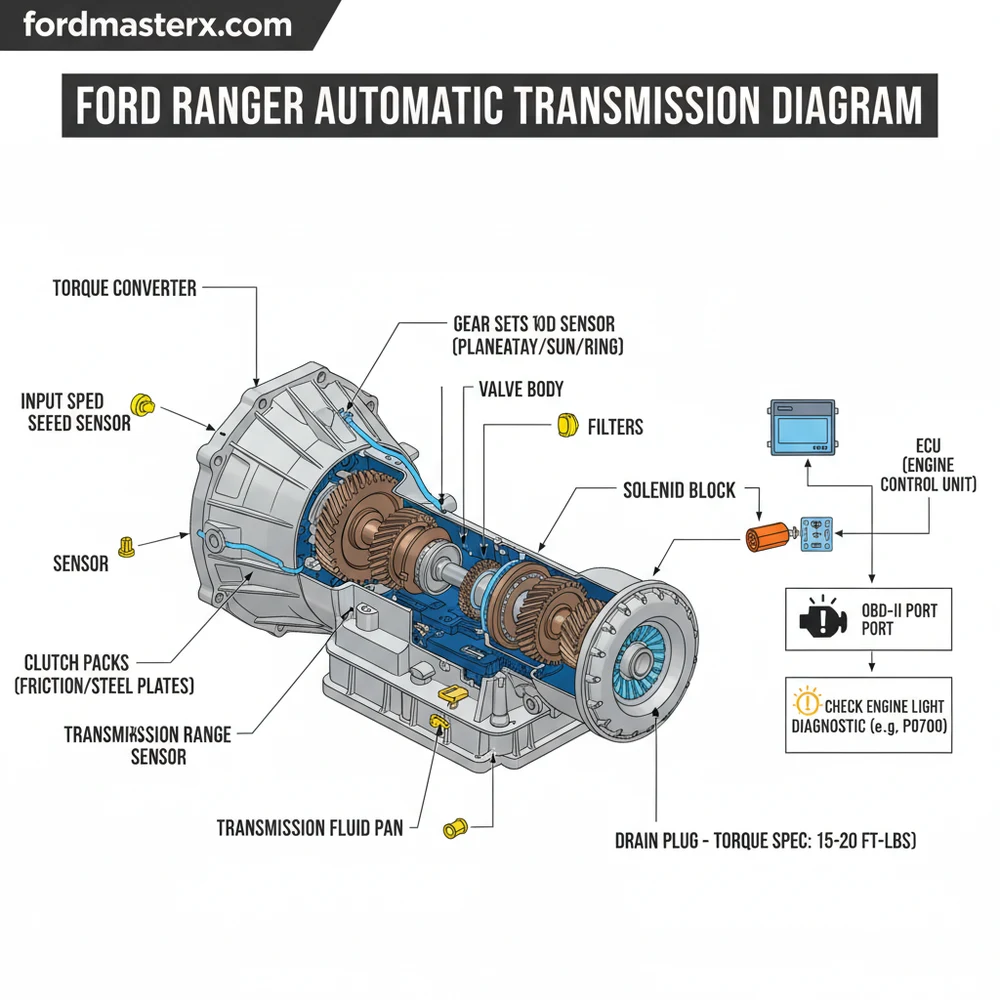
[DIAGRAM_PLACEHOLDER – Ford Ranger Automatic Transmission Components: Torque Converter, Valve Body, Solenoid Pack, and Case Housing]
Reading a ford ranger automatic transmission diagram requires a systematic approach to avoid being overwhelmed by the hundreds of individual parts. Follow these steps to interpret the diagram and apply it to your repair project:
- ✓ Step 1: Orient the View – Determine if the diagram is an “exploded view” (showing parts separated) or a “sectional view” (showing how parts fit together inside). Most repair manuals use exploded views for part identification.
- ✓ Step 2: Connect the ECU and OBD-II – Use the diagram to find the electrical harness connector. Before dismantling any hardware, connect an OBD-II scanner to the vehicle’s diagnostic port to check for stored codes. This helps narrow down which part of the diagram you should focus on.
- ✓ Step 3: Trace the Fluid Path – Locate the transmission cooler lines on the diagram. Following these lines will show you the coolant flow from the transmission to the radiator and back, which is essential for diagnosing overheating issues.
- ✓ Step 4: Identify the Solenoid Block – Find the solenoid pack on your diagram. If you have a specific diagnostic code related to “Shift Solenoid A,” the diagram will show you exactly which pin on the connector corresponds to that solenoid.
- ✓ Step 5: Verify Hardware and Fasteners – Transmission pans and internal housings require a specific torque spec for every bolt. Use the diagram’s legend to find the correct tightness levels to prevent fluid leaks or stripped threads.
- ✓ Step 6: Check Peripheral Components – While focusing on the transmission, use the diagram to see how it sits near the engine. Note the proximity of the accessory belt and the timing chain area at the front of the engine, as these can sometimes produce noises that are mistaken for transmission growls.
To perform these tasks, you will need a standard socket set, a torque wrench, a digital multimeter for electrical testing, and a drain pan for fluid management. Always wear safety glasses and use heavy-duty jack stands if you are working underneath the vehicle.
Transmission fluid can reach extremely high temperatures. Never attempt to disconnect cooler lines or remove the transmission pan immediately after driving the vehicle. Allow at least one hour for the system to cool down.
When problems arise, the ford ranger automatic transmission diagram becomes your primary troubleshooting tool. One of the most common issues is the illumination of the check engine light or a flashing “O/D Off” light. When the ECU detects a discrepancy between the input and output speeds, it triggers a diagnostic code (such as P0730 for incorrect gear ratio). By referencing the diagram, you can identify if the issue is likely a slipping clutch (mechanical) or a failed speed sensor (electrical).
Another frequent problem is delayed engagement or “hunting” for gears. This is often caused by a drop in hydraulic pressure. Use your diagram to locate the main pressure regulator valve within the valve body. If debris has clogged this area, the transmission will struggle to apply enough force to the gear sets. If you notice fluid leaking from the front of the unit, the diagram will point you toward the pump seal or torque converter O-ring. If basic troubleshooting—such as checking fluid levels or scanning for codes—does not resolve the issue, or if you find heavy metal shavings in the pan, it is time to seek professional help from a transmission specialist.
When replacing a transmission filter, always check the magnet at the bottom of the pan. A small amount of “clutch dust” is normal, but large metal chunks indicate a mechanical failure within the planetary gears or bearings shown on your diagram.
For long-term reliability, following best practices is essential. Heat is the number one enemy of any automatic gearbox. Ensure that the coolant flow through the transmission cooler is unobstructed. If you frequently tow heavy loads with your Ford Ranger, consider installing an auxiliary cooler. This is usually shown in advanced diagrams as an add-on component in the return line.
Maintenance also extends to the engine side of the equation. While it may seem unrelated, a worn accessory belt or a failing timing chain can cause engine vibrations that are transferred through the torque converter, potentially damaging the transmission’s front pump over time. Always use the specific type of fluid recommended by the manufacturer; modern Ford transmissions are highly sensitive to fluid viscosity and additive packages. Using the wrong fluid can lead to solenoid failure and seal degradation.
By combining a clear ford ranger automatic transmission diagram with systematic diagnostic steps, you can save thousands of dollars in repair costs and extend the life of your truck. Whether you are performing a simple fluid swap or a complex solenoid replacement, the diagram remains your most valuable tool for ensuring the job is done right the first time. Quality components and a disciplined approach to the torque spec of every bolt will ensure your Ranger remains a reliable workhorse for years to come.
Step-by-Step Guide to Understanding the Ford Ranger Automatic Transmission Diagram Guide
Identify the specific transmission model using the door jamb sticker code.
Locate the transmission pan and external fluid lines on the diagram.
Understand how the ECU communicates with the internal solenoid pack through the harness.
Apply the correct torque spec when reinstalling the pan bolts to prevent leaks.
Verify that all electrical connectors are seated firmly and free of corrosion.
Complete the process by using a scanner to clear any old diagnostic code.
Frequently Asked Questions
Where is the transmission control solenoid located?
The transmission control solenoid is located inside the transmission oil pan, attached to the valve body. To access it, you must drain the fluid and remove the pan. This component is responsible for controlling fluid flow to the clutches based on signals sent by the vehicle’s onboard computer system.
What does this automatic transmission diagram show?
The diagram shows the assembly of internal gears, the torque converter, and hydraulic circuits. It also details the electrical harness connections and the location of sensors like the Output Shaft Speed (OSS) sensor, providing a comprehensive map for both mechanical repair and electrical circuit testing on your truck.
How many electrical connections does the transmission have?
Depending on the specific year, most Ford Ranger transmissions feature a large main harness connector with 10 to 16 pins. This connector links the internal solenoids and thermistors to the ECU, allowing the engine and transmission to synchronize shifting patterns based on load, speed, and throttle position.
What are the symptoms of a bad transmission sensor?
Symptoms include a flashing check engine light or ‘O/D Off’ light, erratic shifting, or the vehicle entering ‘limp mode.’ You will often find a specific diagnostic code when using an OBD-II scanner, such as P0750 or P0720, indicating a circuit failure in the transmission’s electronic control system.
Can I replace the solenoids myself?
Yes, replacing the solenoid pack is a feasible DIY task for those comfortable with fluid changes. By removing the transmission pan, you can access the valve body. However, cleanliness is critical; even a tiny speck of lint can clog hydraulic passages and cause significant transmission failure or erratic behavior.
What tools do I need for transmission diagnostics?
You will need a basic socket set for pan removal, a torque wrench to meet the specific torque spec for bolts, and an OBD-II scanner to read fault codes. A multimeter is also essential if you need to test the continuity of the wiring harness or sensor resistance.


