Ford Parts Catalog with Diagrams: Complete Guide
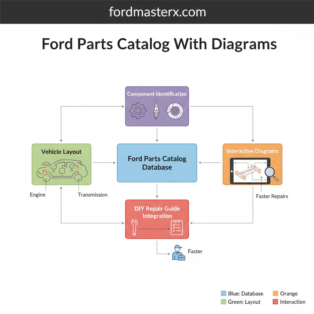
A Ford parts catalog with diagrams provides a visual breakdown of a vehicle’s entire system. It allows users to identify the exact structure and configuration of parts, ensuring correct ordering. By viewing the exploded layout, mechanics can see how each individual component fits within the larger assembly, simplifying complex repair tasks.
📌 Key Takeaways
- Exploded views illustrate the precise relationship between parts
- Identify specific OEM part numbers for accurate ordering
- Visualizing assembly sequences prevents common installation errors
- Use VIN filters to match the diagram to your specific configuration
- Essential for both routine maintenance and complex mechanical repairs
When you are tackling a DIY repair or simply trying to understand the inner workings of your vehicle, finding the right information is the first step toward success. Navigating the complexities of modern automotive engineering requires more than just a basic toolkit; it requires a precise ford parts catalog with diagrams to act as your roadmap. These technical resources provide a comprehensive overview of your vehicle’s internal configuration, allowing you to identify every specific component without the guesswork. In this guide, we will explore how to interpret these professional schematics, understand the underlying structure of various vehicle systems, and use these blueprints to streamline your maintenance and repair process.
A Ford parts catalog is organized by “groups” and “subgroups.” For example, Group 6000 typically covers the engine, while Group 2000 covers the braking system. Understanding these high-level categories is essential for navigating the catalog efficiently.
The layout of a standard parts diagram is designed to show the relationship between individual components within a larger system. Most catalogs utilize an “exploded view” schematic. This visual style takes a complex assembly—such as a transmission or a cylinder head—and “explodes” it, showing each bolt, seal, and gear in the exact order and orientation in which they are installed. This configuration is vital because it reveals the hidden structure of the assembly that you cannot see when the part is fully installed on the vehicle.
Within these diagrams, you will notice specific labeling conventions. Most Ford schematics use callout numbers. These are not the full part numbers, but rather “base numbers” that identify what the part is (for example, 2001 always refers to brake pads). To get the full, orderable part number, you must combine this base number with the prefix and suffix specific to your vehicle’s year and model. The diagram also highlights the connectivity of the system, using dotted lines or arrows to indicate where a sub-assembly fits into the primary chassis or engine block. Color-coding is rare in traditional black-and-white blueprints, but modern digital catalogs may use highlighting to distinguish between different engine displacements or trim levels, ensuring you don’t accidentally order a component for a V8 when you drive an EcoBoost I4.
    [ DIAGRAM: TYPICAL EXPLODED VIEW LAYOUT ]

    (Part A) --- [Bolt 1A]
       |
    (Part B) <--- [Gasket 2B] --- [Seal 3B]
       |
    (Main Housing)
       |
    [Bracket 4C] --- (Mounting Point)

    Legend:
    - Solid Lines: Physical Connection
    - Dotted Lines: Assembly Path
    - Numbers: Catalog Callouts
Figure 1.0: Conceptual representation of a system component layout found in a professional parts catalog.
Step-by-Step Guide to Reading and Using the Catalog
Interpreting a complex automotive schematic is a skill that combines technical observation with logical deduction. Follow these steps to master the use of your parts catalog:
-
✓ Step 1: Identify Your VIN (Vehicle Identification Number)
The VIN is the most critical piece of data. Because manufacturers often change parts mid-production, the VIN ensures the catalog filters out components that do not apply to your specific build date or assembly plant. -
✓ Step 2: Select the Correct System Category
Navigate to the primary system you are working on. Most catalogs are divided into Engine, Transmission, Suspension, Electrical, and Body. Use the high-level overview to drill down into the specific sub-system, such as “Alternator Mounting” or “Rear Leaf Springs.” -
✓ Step 3: Analyze the Exploded View
Once you find the schematic, study the orientation of the parts. Note how seals and washers are layered. This “blueprint” perspective is often the only way to know if a previous owner or mechanic installed a component backward or missed a crucial shim. -
✓ Step 4: Cross-Reference Callout Numbers
Locate the component on the diagram and find its callout number (e.g., 5A212). Match this number to the parts list usually located below or beside the image. This list will provide the full nomenclature and any specific fitment notes, such as “Left Side Only” or “Heavy Duty Suspension Package.” -
✓ Step 5: Verify Quantities
The catalog will indicate the “Quantity Required” for a complete repair. If the diagram shows a bolt but the list says “Qty: 8,” you know that the entire assembly requires eight of those specific fasteners, even if only one is shown in the exploded view for clarity. -
✓ Step 6: Check for Superseded Part Numbers
Parts are frequently updated to fix design flaws. A quality catalog will list “Superseded” numbers. If your old part has a different number than the one in the diagram, the catalog will confirm if the new number is the correct, updated replacement.
Always wear appropriate safety gear, including eye protection and gloves, when verifying parts on a vehicle. Never rely solely on a diagram for torque specifications; always consult a service manual for specific tightening sequences and values to prevent component failure.
Common Issues & Troubleshooting

Even with a high-quality Ford parts catalog with diagrams, users may encounter obstacles. One frequent problem is “mid-year transitions.” Manufacturers sometimes change a component supplier in the middle of a production cycle. In these cases, the diagram might show two different versions of a part. To solve this, you must look for “Build Date” notations in the catalog (e.g., “Produced before 05/12/10”).
Another common issue is the “Part Not Illustrated” error. Sometimes small items like generic clips, standard nuts, or internal wiring pigtails are listed in the text but do not appear in the visual schematic. If you cannot find a component in the layout, check the “Miscellaneous” or “Hardware” subsection of that specific category. Additionally, if a diagram looks significantly different from what you see under your hood, verify that you haven’t selected a diagram for an export model or a different engine variant. If the physical layout of your vehicle’s system doesn’t match the blueprint, stop immediately to avoid ordering incorrect and non-returnable electrical components.
When using a digital parts catalog, use the “search” function to look for keywords like “kit.” Often, Ford offers a component kit (which includes gaskets and seals) for a lower price than buying each individual piece shown in the diagram.
Tips & Best Practices for Maintenance

To get the most out of your parts catalog, adopt a systematic approach to your vehicle maintenance. First, always prioritize Original Equipment Manufacturer (OEM) parts for critical systems like sensors, timing components, and internal engine seals. While aftermarket options exist, the dimensions and tolerances in the official catalog diagrams are designed specifically for OEM specifications, ensuring a perfect fit and long-term reliability.
Secondly, keep a digital or printed folder of the diagrams for the specific repairs you have performed. This creates a personalized service history and makes it much easier to find part numbers for future maintenance, such as filter replacements or brake jobs. When it comes to cost-saving, use the catalog to identify “common parts.” Many fasteners and minor brackets are used across multiple vehicle lines. By identifying the base part number, you can sometimes find the same component at a lower price point listed under a different model that uses the same configuration.
Finally, always cross-reference your findings with a VIN-based search tool. Most modern Ford parts catalog with diagrams interfaces allow you to “lock in” your VIN. This filters the entire database so that you only see components that were actually installed on your vehicle’s assembly line. This eliminates the risk of ordering parts for a 2WD version of your truck when you actually own a 4WD, or vice versa. By combining the visual clarity of these blueprints with the data accuracy of a VIN search, you can approach any automotive project with the confidence of a professional technician. Using these diagrams effectively not only saves time but ensures that every repair restores your vehicle to its original factory structure and safety standards.
Frequently Asked Questions
Where is the component located?
Components are found within specific system sub-sections, such as the engine or chassis, in the catalog. By selecting your vehicle model, you can navigate through the hierarchical structure to find the exact physical location of any part within the overall vehicle layout and assembly.
What does this diagram show?
This catalog shows an exploded view of automotive assemblies, detailing every individual component, bolt, and bracket. It illustrates the spatial relationship and assembly order, helping users understand the mechanical structure and identifying specific part numbers required for maintenance or repair of various Ford vehicle systems.
How many connections does a typical system have?
The number of connections depends on the specific system configuration being viewed. For example, a cooling system diagram might show dozens of hose connections and clamps, while an electrical harness diagram illustrates numerous pin connectors and ground points necessary for the vehicle’s electronic communication.
What are the symptoms of a bad component?
Symptoms vary by system, but using a diagram helps you trace the root cause. If you notice leaks, noises, or electrical failures, cross-referencing the affected area with the catalog layout allows you to identify which seals, bearings, or sensors are likely failing and need replacement.
Can I replace this myself?
Many repairs are DIY-friendly when using a Ford parts catalog with diagrams as a reference. The visual assembly guide provides clarity on how parts fit together, though complex tasks involving the engine or transmission may require specialized tools and professional mechanical knowledge to ensure safety.
What tools do I need for this task?
Basic repairs usually require a standard socket set, screwdrivers, and pliers. However, specialized tasks identified in the diagram may necessitate torque wrenches, pullers, or diagnostic scanners. Always check the specific component assembly in the catalog to determine if unique fasteners require specialized automotive tools.


